Paradox Magellan MG5000 Programming Manual
32-zone wireless transceiver security spectra sp series magellan series systems and 32-zone wireless transceiver security systems
Hide thumbs
Also See for Magellan MG5000:
- Programming manual (48 pages) ,
- User manual (32 pages) ,
- Reference & installation manual (69 pages)
Table of Contents

Subscribe to Our Youtube Channel
Related Manuals for Paradox Magellan MG5000


Summary of Contents for Paradox Magellan MG5000
-
Page 1: Programming Guide
32-Zone Wireless Transceiver Security Systems MG5000 Version 4.7 MG5050 Version 4.7 MG5050E Version 4.96 4 to 32-Zone Expandable Security Systems SP5500 • SP6000 • SP7000 Version 4.92 SP4000 • SP65 Version 5.16 Programming Guide... - Page 2 Limitations of Alarm Systems It must be understood that while your Paradox alarm system is highly advanced and secure, it does not offer any guaranteed protection against burglary, fire or other emergency (fire and emergency options are only available on certain Paradox models). This is due to a number of reasons, including by not limited to inadequate or improper installation/positioning, sensor limitations, battery performance, wireless signal interruption, inadequate maintenance or the potential for the system or telephone lines to be compromised or circumvented.
-
Page 3: About This Programming Guide
Things You Need to Know About this Programming Guide Use this programming guide to record programmed settings for your Magellan or Spectra SP control panel. This programming guide should be used along with the Magellan and Spectra SP Reference & Installation Manual (available online), whenever installing or programming your Magellan or Spectra SP system. - Page 4 Data Entry and Display To access the data display mode, access the desired section and press before entering any data. Depending on the keypad(s) ENTER configured to your system, specific LEDs or icons will flash, thus indicating that you are in data display mode. Each time ENTER pressed, the keypad will display the next digit in the current section, and will continue to do so through all the remaining sections, one digit at a time, without changing the programmed values;...
-
Page 5: Table Of Contents
Contents Description of Sections [700] to [704] ........37 Zone Options ................38 ATZ Options ..........................38 Installer Quick Menu ..............7 General Zone Options ....................... 38 Zones ............................... 7 Miscellaneous System Options ....................39 Delays ............................. 7 System Timers .................39 Time and Date ..........................7 Walk Test Mode .......................... - Page 6 PCB Layouts/Wiring Diagrams ..........61 MG5000 ............................61 MG5050 ............................62 SP4000 ............................63 SP5500 ............................64 SP6000 ............................65 SP65 ............................... 66 SP7000 ............................67 Appendix A ................68 EN 50131 Programming ......................68 ATZ Options ..........................68 General Zone Options ....................... 69 Miscellaneous System Options ....................
-
Page 7: Installer Quick Menu
Magellan & Spectra SP • Programming Guide Walk Test Mode Installer Quick Menu Step Action Details = flash; maintenance code may also be + installer code used Zones Activates or deactivates walk test mode Step Action Details Installer and Maintenance Codes = flash;... -
Page 8: Communicator
Magellan & Spectra SP • Programming Guide Communicator Keypad Input/Output Configuration (K636 V2.0 and higher) Step Action Details Step Action Details + installer code = flash ENTER STAY = flash; maintenance code may also be + installer code used Press and hold ENTER = ON STAY... -
Page 9: System Planning
Magellan & Spectra SP • Programming Guide System Planning Bus Module Planning Worksheet 1: Planning Bus Modules Serial # Sticker Description Path Zone (Entry Point) Path Zone Path Zone Path Zone Bus Module 1 Bus Module 2 Bus Module 3 Bus Module 4 Bus Module 5 Bus Module 6... -
Page 10: Wireless Keypad Planning
Magellan & Spectra SP • Programming Guide Wireless Keypad Planning Worksheet 2: Planning Wireless Keypads Serial # Sticker Description Path Zone (Entry Point) Path Zone Path Zone Path Zone Wireless Keypad Wireless Keypad Wireless Keypad Wireless Keypad Wireless Keypad Wireless Keypad Wireless Keypad Wireless Keypad NOTE: When deleting a wireless keypad (K32RF/K37) from the system, the corresponding StayD path zones will also be deleted. -
Page 11: Programmable Output (Pgm) Planning
Magellan & Spectra SP • Programming Guide Programmable Output (PGM) Planning Worksheet 4: Planning Programmable Outputs Serial # Sticker Description Serial # Sticker Description PGM 1 PGM 9 PGM 2 PGM 10 PGM 3 PGM 11 PGM 4 PGM 12 PGM 5 PGM 13 PGM 6... - Page 12 Magellan & Spectra SP • Programming Guide Worksheet 6: Planning Zones (Continued) Arming Method Arming Method Serial # Sticker Zone # Zone Description Stay Sleep Full Serial # Sticker Zone # Zone Description Stay Sleep Full ...
-
Page 13: Zone Recognition
Magellan & Spectra SP • Programming Guide Zone Recognition NOTE: For keypad zone programming, see Keypad Programming on page 8. MG Series When expanding zones via ZX8, up to three ZX8 modules can be added to the system, and they are identified by the ZX8 three-position jumpers: +1, +9, and +17. Table 3 displays zone recognition information for MG control panels. -
Page 14: Sp Series
SP Series When expanding zones via ZX8, up to three ZX8 modules can be added to the system, and they are identified by the ZX8 three-position jumpers: +1, +9, and +17. Table 4 displays zone recognition information for SP control panels. Table 4: Zone recognition information for the SP series SP4000 (without ATZ) SP4000 (with ATZ) - Page 15 Table 4: Zone recognition information for the SP series (Continued) SP65 (without ATZ) SP65 (with ATZ) SP7000 (without ATZ) SP7000 (with ATZ) Type Zone Description Type Zone Description Type Zone Description Type Zone Description Panel input 1 Panel input 1A Panel input 1 Panel input 1A Panel input 2...
-
Page 16: Zone Definitions
Magellan & Spectra SP • Programming Guide Zone Definitions NOTE: If a device is assigned to a zone which is already programmed, a wireless zone will overwrite a keypad/hardwire zone and a keypad zone will overwrite a hardwire zone. To define zones on your MG/SP control panel: Press , and then enter your installer code (maintenance code may also be used). -
Page 17: Worksheet 7: Zone Definitions
Table 9: Permitted zone definitions for MG/SP panels Arming Type Arming Type Input Input Description Description Stay Sleep Fully Stay Sleep Fully Value Value Disarm Disarm Zone disabled 24 hr. burglary ... -
Page 18: Custom Zone Definitions
Magellan & Spectra SP • Programming Guide Custom Zone Definitions With MG/SP control panels you can create up to four custom zone definition templates (use worksheet 8). Custom zone definition templates (sections [033] to [036]) will overwrite zone definitions 33 to 36 in table 5 on page 16. Modifications can be made in accordance with table 9 (Permitted zone definitions for MG/SP panels), on page 17. -
Page 19: Wireless Zone Assignment
Magellan & Spectra SP • Programming Guide Wireless Zone Assignment Use the following section to program the wireless zones on your MG/SP control panel. Use worksheet 11 to record your settings. Worksheet 11: Wireless Zones Section Zone Wireless Zone (Serial #) Section Zone Wireless Zone (Serial #) -
Page 20: Zone Labels
Magellan & Spectra SP • Programming Guide Zone Labels Use worksheet 13 to record your settings when programming zone labels. Worksheet 13: Zone Labels Section Zone Zone Label Section Zone Zone Label __/__/__/__/__/__/__/__/__/__/__/__/__/__/__/__ __/__/__/__/__/__/__/__/__/__/__/__/__/__/__/__ [181] [197] __/__/__/__/__/__/__/__/__/__/__/__/__/__/__/__ __/__/__/__/__/__/__/__/__/__/__/__/__/__/__/__ [182] [198] __/__/__/__/__/__/__/__/__/__/__/__/__/__/__/__ __/__/__/__/__/__/__/__/__/__/__/__/__/__/__/__ [183]... -
Page 21: Description Of Mg/Sp Events
Magellan & Spectra SP • Programming Guide Description of MG/SP Events Table 12: List of events for MG/SP control panels Event Group Event Group Description Sub-group Sub-group Description Zone OK 01 to 32 Zone number Zone open Any zone number 00 to 01 Silent alarm Buzzer alarm... - Page 22 Magellan & Spectra SP • Programming Guide Table 12: List of events for MG/SP control panels (Continued) Event Group Event Group Description Sub-group Sub-group Description IP registration status change GPRS registration status change Armed with trouble(s) Non-reportable event Supervision alert (Cont.) (Cont.) Supervision alert restore...
- Page 23 Magellan & Spectra SP • Programming Guide Table 12: List of events for MG/SP control panels (Continued) Event Group Event Group Description Sub-group Sub-group Description Non-valid source ID WinLoad/BabyWare direct WinLoad/BabyWare through IP module WinLoad/BabyWare through GSM module WinLoad/BabyWare through modem Software access (VDMP3, IP100, WinLoad, BabyWare) IP100 direct VDMP3 direct...
- Page 24 Magellan & Spectra SP • Programming Guide Table 12: List of events for MG/SP control panels (Continued) Event Group Event Group Description Sub-group Sub-group Description 01 to 32 Zone number Zone alarm restore Any zone number 01 to 32 Zone number Fire alarm restore Any zone number Panic non-medical emergency...
- Page 25 Magellan & Spectra SP • Programming Guide Table 12: List of events for MG/SP control panels (Continued) Event Group Event Group Description Sub-group Sub-group Description AC failure Battery failure Auxiliary current overload Bell current overload Bell disconnected Clock loss Fire loop trouble Fail to communicate with monitoring station telephone # 1 Fail to communicate with monitoring station telephone # 2 Fail to communicate with voice report...
- Page 26 Magellan & Spectra SP • Programming Guide Table 12: List of events for MG/SP control panels (Continued) Event Group Event Group Description Sub-group Sub-group Description Bus/EBus/wireless module communication fault Tamper trouble Bus/EBus/wireless module new trouble (partition 1 only) Power fail Battery failure Any bus module new trouble event Bus/EBus/wireless module communication fault restore...
-
Page 27: Pgm Activation/Deactivation Events
Magellan & Spectra SP • Programming Guide Table 12: List of events for MG/SP control panels (Continued) Event Group Event Group Description Sub-group Sub-group Description 01 to 32 User number Non-medical alarm (paramedic) Any user number 01 to 32 Zone number Zone forced Any zone number Zone included... -
Page 28: Pgm Options
Magellan & Spectra SP • Programming Guide PGM Options Table 13: Description of PGM options PGM 1 [261] PGM 2 [262] PGM 3 [263] PGM 4 [264] PGM 5 [265] PGM 6 [266] PGM 7 [267] PGM 8 [268] Option Description ... -
Page 29: Pgm Delays
Magellan & Spectra SP • Programming Guide PGM Delays Use worksheet 15 to record your settings for the MG/SP PGM delays. Worksheet 15: PGM Delays Section PGM Delay Value Default Section PGM Delay Value Default [281] PGM 1 ___/___/___ (001 to 255 x 1 sec./min.) [289] PGM 9 ___/___/___... -
Page 30: User Programming
Magellan & Spectra SP • Programming Guide User Programming Use the following section to program the various user features on your MG/SP control panel. System Codes Use worksheet 18 to record your settings for the MG/SP system codes. For access options, see section [701], in table 25 on page 37. NOTE: The maintenance code cannot access the following sections: [395] (Installer code lock);... -
Page 31: User Report Codes
Magellan & Spectra SP • Programming Guide User Report Codes Use worksheet 20 to record your settings for the MG/SP user report codes (the default code is FF). To clear and reset these codes, see Description of Sections [966] and [967] on page 54. -
Page 32: Wireless Repeater Signal Strength
Wireless Repeater Signal Strength The signal strength for wireless repeaters is visible in sections [548] and [549]; these sections represent repeaters 1 and 2, respectively. To view the signal strength, proceed as follows: Enter the wireless repeater’s respective section (e.g., for repeater 1, enter section [548]). Press the repeater’s anti-tamper switch. -
Page 33: Wireless Repeater Labels
Magellan & Spectra SP • Programming Guide Wireless Repeater Labels Use worksheet 23 to record your settings for wireless repeater labels. To reset these labels, see Description of Section [965] on page 53. Worksheet 23: Wireless Repeater Labels Section Description Wireless Repeater Label [568] Repeater 1... -
Page 34: Wireless Keypad Signal Strength
Magellan & Spectra SP • Programming Guide Wireless Keypad Signal Strength The signal strength for wireless keypads is visible in sections [591] to [598]; these sections represent keypads 1 through 8, respectively. To view the signal strength, proceed as follows: Enter the wireless keypad’s respective section (e.g., for keypad 1, enter section [591]). -
Page 35: Worksheet 26: Programming Remote Controls
Worksheet 26: Programming Remote Controls REM3 Remote Control REM1/REM2/RAC1/RAC2/REM15 PGM 1 PGM 2 PGM 3 PGM 4 PGM 5 PGM 6 PGM 3 & 4 PGM 5 & 6 + Default Data Disabled Disabled Default Data Disabled RC # Section RC # Section... -
Page 36: User Assignment For Remote Controls
Magellan & Spectra SP • Programming Guide User Assignment for Remote Controls Table 23: User assignment per remote control Section Description Section Description Section Description Section Description RC 1 for user 1 RC 9 for user 9 RC 17 for user 17 RC 25 for user 25 [651] [659]... -
Page 37: Cancelling The Tamper Supervision For Wireless Sirens
Cancelling the Tamper Supervision for Wireless Sirens To cancel tamper supervision, access section [695], and then press . The tamper supervision is disabled until the cover is replaced or after 30 minutes have elapsed. ENTER Description of Sections [700] to [704] The following section provides information on sections [700] to [704]. -
Page 38: Zone Options
Magellan & Spectra SP • Programming Guide Zone Options Use the following section to program zone options for your MG/SP control panel. ATZ Options Table 26: Description of section [705] Option Description ATZ zone doubling Disabled Enabled ... -
Page 39: Miscellaneous System Options
Magellan & Spectra SP • Programming Guide Miscellaneous System Options Table 29: Description of section [708] Option Description Enter code to view trouble One-touch Enter code Enter code to view alarm in memory/event list One-touch Enter code ... -
Page 40: Country Codes
Magellan & Spectra SP • Programming Guide Country Codes Table 31 lists countries and their respective codes. This information is required when programming section [731] (see worksheet 31 for details). Table 31: Country codes for MG/SP control panels Input Value Country Input Value Country Mexico;... -
Page 41: Partition Timers
Magellan & Spectra SP • Programming Guide Table 33: Description of partition 2 options (section [742]) Option Description Option Description Auto-arm on time Disabled Enabled Auto-arm on no movement Disabled Enabled Regular (default) See options 3 See options 3 3 &... -
Page 42: Communication Programming
Magellan & Spectra SP • Programming Guide Communication Programming Use the following section to program various communication features on your MG/SP control panel. Table 34 lists features available for each MG/SP control panel. Prioritization of signals and messages are based on a “first in, first out” scheme. Systems meet EN 50136 ATS2 or ATS3 requirements when configured as depicted. NOTE: For increased security, it is suggested that redundant communication methods be installed. -
Page 43: Event Call Direction Options
Magellan & Spectra SP • Programming Guide Table 37: Auto-test report transmission options (section [801]) The test report code will be transmitted when the conditions in entries 2 or 3 above (option 3 = OFF and option 4 = ON; option 3 = ON and option 4 = OFF), are met. -
Page 44: Report Codes And Partition Accounts
Magellan & Spectra SP • Programming Guide Report Codes and Partition Accounts Use worksheet 36 to record your settings for sections [810] to [812]. Worksheet 36: Report Codes and Partition Accounts Section Data Description Tel. 1 & Tel. 2; Reporting format: [810] ___/___ 0 = Ademco Slow;... -
Page 45: Test Report And Report Delays
Magellan & Spectra SP • Programming Guide Test Report and Report Delays Use worksheet 40 to record your settings for sections [850] to [852]. For additional timers, see worksheets 38 and 49 on pages 44 and 51, respectively. Worksheet 40: Test Report and Report Delays Section Data Description... -
Page 46: System Trouble Report Codes
Magellan & Spectra SP • Programming Guide System Trouble Report Codes Use worksheet 44 to record your settings for system trouble report codes. Worksheet 44: Special Trouble Report Codes Section Data Description Section Data Description Section Data Description ___/___ ___/___ Bell output overload ___/___ Fail to communicate... -
Page 47: Contact Id Report Codes
Magellan & Spectra SP • Programming Guide Contact ID Report Codes Table 44: Ademco contact ID report codes (Continued) Table 44: Ademco contact ID report codes (Continued) Table 44: Ademco contact ID report codes Type CID # Reporting Code Value Type CID # Reporting Code Value... - Page 48 Magellan & Spectra SP • Programming Guide Table 44: Ademco contact ID report codes (Continued) Table 44: Ademco contact ID report codes (Continued) Table 44: Ademco contact ID report codes (Continued) Type CID # Reporting Code Value Type CID # Reporting Code Value Type CID # Reporting Code...
-
Page 49: Automatic Report Codes
Magellan & Spectra SP • Programming Guide Automatic Report Codes Table 45: List of automatic report codes System Event Default Contact ID Report Code Default SIA Report Code Arming with user code (##) 3 4A1 Close by user Closing report Auto arming 3 4A3 Automatic close... - Page 50 Magellan & Spectra SP • Programming Guide Table 45: List of automatic report codes (Continued) System Event Default Contact ID Report Code Default SIA Report Code Bell absent 1 321 Bell 1 Bell fault Clock lost 1 626 Time/date inaccurate Time changed Fire loop trouble 1 373...
-
Page 51: Communication Report Codes
Magellan & Spectra SP • Programming Guide Table 45: List of automatic report codes (Continued) System Event Default Contact ID Report Code Default SIA Report Code RF zone supervision lost 1 381 Loss of supervision - RF Untype zone supervision RF zone supervision restore 3 381 Supervision restore - RF... -
Page 52: Winload/Babyware Options
Magellan & Spectra SP • Programming Guide WinLoad/BabyWare Options Use worksheet 50 to record your settings for WinLoad and BabyWare options. Worksheet 50: WinLoad/BabyWare Options Section Data Description [910] ___/___/___/___ Panel ID [911] ___/___/___/___ PC password [915] __/__/__/__/__/__/__/__/__/__/__/__/__/__/__/__/__/__/__/__/__ PC telephone number (landline/GSM communication only) WARNING: For increased communication security, change the default panel ID and PC password. -
Page 53: Usability Sections
Magellan & Spectra SP • Programming Guide Worksheet 53: IP Receiver 1 Configuration Section Data Description Default WAN1 IP address (e.g., ); for one or 100.100.100.100 [929] __/__/__ . __/__/__ . __/__/__ . __/__/__ two-digit numbers, add s before the first digit [930] __/__/__/__/__ WAN1 IP port 10000... -
Page 54: Description Of Sections [966] And [967]
Magellan & Spectra SP • Programming Guide NOTE: When resetting any option in section [965], ensure that all other options are deselected. Press to reset the respective set of labels to their default ENTER values, before exiting the section. Description of Sections [966] and [967] Table 50: Description of sections [966] and [967] (clear and reset report codes) Option Description Option Description... -
Page 55: Catalogues Of Special Characters
Magellan & Spectra SP • Programming Guide Catalogues of Special Characters The following section outlines the different catalogues of special characters, including those in Hebrew, Greek, and Russian. Figure 1: Standard special characters Figure 2: Hebrew special characters Figure 4: Greek special characters Figure 3: Russian special characters A069 Figure 5: Polish, Hungarian, and Turkish special characters... -
Page 56: Keypad Letter Assignments
Magellan & Spectra SP • Programming Guide Keypad Letter Assignments The following section outlines the different configurations for keypad letter assignments, including those in Hebrew, Greek, and Russian. Table 53: Standard keypad letter assignment Figure 6: Hebrew keypad letter assignment Press Key Press Key Press Key... - Page 57 Magellan & Spectra SP • Programming Guide Table 55: Description of troubles for MG/SP control panels Telephone line monitoring on control panel Fail to communicate on monitoring telephone 1, on control panel Fail to communicate on monitoring telephone 2, on control panel Fail to communicate on voice telephone, on control panel Fail to communicate with PC, on control panel Communication trouble...
-
Page 58: Product Compatibility Chart
WinLoad Software BabyWare Requires RTX3/RX1 Requires RTX3 Requires modules V5.00 only NOTE: For the most up-to-date and comprehensive MG/SP product compatibility chart, always refer to paradox.com. 58 | Product Compatibility Chart Version 4.7/4.92/5.12... -
Page 59: Hardware Connections
Magellan & Spectra SP • Programming Guide Hardware Connections Single Zone Inputs NOTE: Keyswitches are connected as standard zones and will follow ATZ options 1 and 2, programmed in section [705] (see page 37). Advanced Technology Zone (ATZ) Connections Version 4.7/4.92/5.12 Hardware Connections | 59... -
Page 60: Connecting Fire Circuits
Magellan & Spectra SP • Programming Guide Connecting Fire Circuits For 4-wire installation, program the activation event so that the smoke detectors can be reset by simultaneously pressing for three seconds (see CLEAR ENTER event group 06 on page 21). For 2-wire installation, press simultaneously to automatically reset smoke detectors (not applicable to SP5500, SP4000, CLEAR ENTER... -
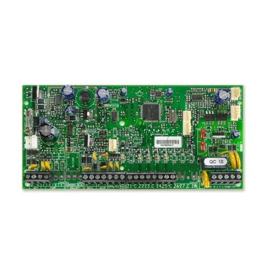
Page 61: Pcb Layouts/Wiring Diagrams
SELF-CONTAINED BELL/SIREN 1 Used for connecting the IP100 Internet Module; also used for In-Field 6 Paradox Memory Key (PMC-4, PMC5) Firmware upgrade through a 307USB Direct Connect Interface 7 Refer to Hardware Connections on page 59 2 EBUS and Dialer used with:... -
Page 62: Mg5050
SELF-CONTAINED place, and connect the wires (not shown) to a zone input BELL/SIREN programmed for tamper. 1 Paradox Memory Key (PMC-4, PMC5) 7 Refer to Panel Reset on page 3 2 J3 ( ) and J4 ( ) used with:... -
Page 63: Sp4000
11 AWG #14 single conductor solid copper wire Voice Module. 12 Ground clamp 2 Paradox Memory Key (PMC-4, PMC5) 13 Cold water pipe grounding 3 Used for connecting the IP100 Internet Module; also used for In-Field 14 To metallic enclosure Firmware upgrade through a 307USB Direct Connect Interface 15 For the keypad’s zone configurations, see Installer Quick Menu on page 7;... -
Page 64: Sp5500
Magellan & Spectra SP • Programming Guide SP5500 STATUS To provide maximum lightning protection we CHARGE RESET strongly recommend having separate earth connections SERVICE for the dialer and zone KEYPAD ground terminals. SERVICE KEYPAD Disconnect telephone line before servicing. RJ31X CA 38A PGM1 PGM2 BELL... -
Page 65: Sp6000
Firmware upgrade through a 307USB Direct Connect Interface (-) keypad connectors; auxiliary power will shut down if current exceeds 6 Paradox Memory Key (PMC-4, PMC5) 1.1A; if the auxiliary output is overloaded and shuts down, you must 7 Refer to Hardware Connections on page 59 disconnect all loads from the output for at least 10 sec. -
Page 66: Sp65
Voice Module. disconnect all loads from the output for at least 10 sec. before 3 Paradox Memory Key (PMC-4, PMC5) reconnecting any load back to the auxiliary output 4 Used for connecting the IP100 Internet Module; also used for In-Field 17 For the keypad’s zone configurations, see Installer Quick Menu on page 7;... -
Page 67: Sp7000
Firmware upgrade through a 307USB Direct Connect Interface 1.1A; if the auxiliary output is overloaded and shuts down, you must 7 Paradox Memory Key (PMC-4, PMC5) disconnect all loads from the output for at least 10 sec. before 8 Refer to Hardware Connections on page 59... -
Page 68: En 50131 Programming
Magellan & Spectra SP • Programming Guide Appendix A EN 50131 Programming The following sections describe all the programming required for your panel to be EN 50131 compliant (MG5050 version 4.96 or higher). NOTE: The Installer Quick Menu is not available anymore for MG5050 V4.96 or higher. To set your panel to be EN 50131 compliant: Enter section [951] to unlock the software and set EN 50131 defaults. -
Page 69: General Zone Options
Magellan & Spectra SP • Programming Guide Table 62: Description of options 3 & 4 and 6 & 7, in section [705] Option Description RF Zone/Hardwired Zone Tamper Recognition Options Keypad/Bus Module Tamper Recognition Options* Disabled Disabled Trouble only Trouble only When disarmed: trouble only;... -
Page 70: Keypad Lockout
Magellan & Spectra SP • Programming Guide Keypad Lockout Use the following section to program keypad lockout settings for your MG/SP control panel. Use worksheet 30 to record your settings. Worksheet 57: Keypad Lockout Section Data Description Default [716] ___/___/___ 000 to 255 minutes Keypad lockout delay 015 minutes... - Page 72 The whole Paradox team wishes you a successful and easy installation. We hope this product performs to your complete satisfaction. Should you have any questions or comments, please contact us. For support, please contact your local distributor, or dial 1-800-791-1919 (in North America) or +1-450-491-7444 (outside North America), Monday to Friday, from 8:00 a.m.
Need help?
Do you have a question about the Magellan MG5000 and is the answer not in the manual?
Questions and answers