Table of Contents
Advertisement
Advertisement
Table of Contents

Subscribe to Our Youtube Channel
Related Manuals for Jet CS-275


Summary of Contents for Jet CS-275
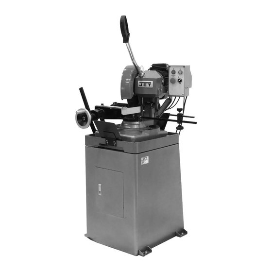
- Page 1 This .pdf document is bookmarked Operating Instructions and Parts Manual Manual Ferrous Cold Saws Models CS-275, CS-315 model CS-275-1 shown 427 New Sanford Road LaVergne, Tennessee 37086 Part No. M-414226 Ph.: 800-274-6848 Revision F 02/2018 www.jettools.com Copyright © 2018 JET...
-
Page 2: Warranty And Service
JET sells through distributors only. The specifications listed in JET printed materials and on official JET website are given as general information and are not binding. JET reserves the right to effect at any time, without prior notice, those alterations to parts, fittings, and accessory equipment which they may deem necessary for any reason ®... -
Page 3: Table Of Contents
16.2.1 CS-315 Cold Saw (Machine Assembly) – Exploded View ..............23 16.2.2 CS-315 Cold Saw (Machine Assembly) – Parts List ................24 16.3.1 CS-275 and CS-315 Cold Saws (Stand Assembly) – Exploded View ..........27 16.3.2 CS-275 and CS-315 Cold Saws (Stand Assembly) – Parts List ............27 17.0 Electrical connections .......................... -
Page 4: Safety Warnings
Do not use this cold saw for other than its A guard or other part that is damaged should intended use. If used for other purposes, JET be properly repaired or replaced. disclaims any real or implied warranty and 19. -
Page 5: Introduction
- - SAVE THESE INSTRUCTIONS - - 4.0 Introduction The JET CS-275 and CS-315 Cold Saws are designed to provide a reliable solution to the needs of machine shops and production environments that work with steel or iron. The saws are manually operated. After clamping the material in the vise, the operator presses the trigger starting the blade, and brings the operating lever downward to cut the material. -
Page 6: Cold Saw Features
5.0 Cold saw features Figure 5-1 Miter cutting head Control panel The miter cutting head is the unit that performs the The panel features independent ON and OFF cut, and is pivoted downward manually by means buttons with indicator light, a mushroom style red of the operating lever. -
Page 7: Specifications
3.2” x 2.6” Table 1 The specifications in this manual were current at time of publication, but because of our policy of continuous improvement, JET reserves the right to change specifications at any time and without prior notice, without incurring obligations. -
Page 8: Unpacking
7.1 Contents of shipping container 7.0 Unpacking Cold Saw Operating Lever Open shipping container, and any secondary Work Stop Assembly boxes. Check for shipping damage; report any Hex Cap Screws with Nuts damage immediately to your distributor and Handle shipping agent. Do not discard any shipping Roller Assembly material until the Cold Saw is assembled and Splash Plates... -
Page 9: Operating Lever
8.1 Operating lever Refer to Figure 8-1. Remove the hex nut and screw from the hole at the front of the saw head (Figure 8-1). These fasteners will not be used again unless the machine needs to be transported in the future. -
Page 10: Length Stop
CS-315-1 (1PH, 230V) Table 2 9.1 Three-phase models Figure 8-4 The CS-275 (3-phase) and CS-315 (3-phase) are 8.6 Length stop rated for 230-volt only power. They are not supplied with a plug. You may either install a Refer to Figure 8-5. -
Page 11: Grounding Instructions
Switch the leads in the coolant pump junction 10.2 Vise box, according to the diagram in Figure 9-2. (A diagram is also included on the coolant pump.) Refer to Figure 10-1. The saw is now ready for 230V operation. The vise is self-centering and has a cam action lever for fast clamping. -
Page 12: Blade Replacement
10.4 Blade replacement Disconnect machine from the power source before changing saw blades. Failure to comply may result in serious injury. To change the saw blade (Figure 10-3): Disconnect machine from power. Clamp a piece of wood in the vise, and lower the blade upon it to prevent rotation. -
Page 13: Maintenance
Pull the operating lever to bring down the 13.4 Lubrication blade into the work piece. You will manually control the speed of the downstroke. For long life and trouble free operation, it is essential that this machine is kept well lubricated. When the cut is complete, release the trigger The vise and leadscrew should be oiled daily. -
Page 14: Blade Selection
14.2 Determining proper tooth pitch Proper tooth pitch depends on: a) the size of the section; b) the hardness of the material; c) wall thickness. Solid sections call for blades with a coarse tooth pitch, while small cross-sections require blades with finer teeth. This is because when Figure 13-2 cutting walls of small... -
Page 15: Coolant
The feeding speed depends on the cross-section 14.7 Teeth shape of the material. Solid or thick-walled materials (thickness>5mm) can therefore be cut at high “ C” TYPE SHARPENING (HZ) speed providing there is sufficient swarf removal by Coarse toothing with roughing tooth raked on both the blade, while thin-walled materials such as sides and non-raked finishing tooth. - Page 16 Figure 14-3 Figure 14-4 Short swarf material such as brass, bronze, Circular saws can also be characterized by other aluminum and hard cast iron require smaller cutting parameters such as the whine reduction feature, angles because the swarf becomes crushed which cuts down noise at high speeds, or immediately and the rake angle has little effect expansion, which compensates for the pushing of...
-
Page 17: Troubleshooting
Check the coolant level and clean coolant lines and Insufficient coolant nozzles. Cuts not straight Feed speed too strong Reduce feed speed. Blade not perpendicular to Adjust blade tracking according to instructions. If this workpiece. proves unsuccessful, contact JET technical support. Table 5... -
Page 18: Machine Fault And Operating Problems
Number of your machine available when you call will allow us to serve you quickly and accurately. Non-proprietary parts, such as fasteners, can be found at local hardware stores, or may be ordered from JET. Some parts are shown for reference only, and may not be available individually. -
Page 19: Cs-275 Cold Saw (Machine Assembly) - Exploded View
16.1.1 CS-275 Cold Saw (Machine Assembly) – Exploded View... -
Page 20: Cs-275 Cold Saw (Machine Assembly) - Parts List
16.1.2 CS-275 Cold Saw (Machine Assembly) – Parts List Index No. Part No. Description Size 1 ....CS275-1G ....Lock Handle ....................1 2 ....CS275-2 ....Lock Nut......................1 3 ....CS275-3 ....Shaft ......................1 4 .... - Page 21 Index No. Part No. Description Size 60 ....BB-6205ZZ ....Ball Bearing ............. 6205ZZ ......2 61 ....CS275-61 ....Rubber Gasket....................1 62 ....TS-1490031 ....Hex Cap Screw ............M8x20 ......4 63 ....TS-0680031 ....Flat Washer ............. 5/16” ......4 64 ....
- Page 22 Index No. Part No. Description Size 112 .... TS-0680031 ....Flat Washer ............. 5/16” ......2 113 .... TS-1504031 ....Socket Head Cap Screw ......... M8x16 ......2 114 .... CS275-114 ....Screw ............... M5x6 ......2 119 .... CS275-119 ....Oil Seal ..............35x47x8 ......1 120 ....
-
Page 23: Cs-315 Cold Saw (Machine Assembly) - Exploded View
16.2.1 CS-315 Cold Saw (Machine Assembly) – Exploded View... -
Page 24: Cs-315 Cold Saw (Machine Assembly) - Parts List
16.2.2 CS-315 Cold Saw (Machine Assembly) – Parts List Index No. Part No. Description Size 1 ....CS275-1G ....Lock Handle ....................1 2 ....CS275-2 ....Lock Nut......................1 3 ....CS275-3 ....Shaft ......................1 4 .... - Page 25 Index No. Part No. Description Size 61 ....CS275-61 ....Rubber Gasket....................1 62 ....TS-1490031 ....Hex Cap Screw ............M8x20 ......4 63 ....TS-0680031 ....Flat Washer ............. 5/16” ......4 64 ....CS275-64G ....Flange ......................1 65 ....
- Page 26 Index No. Part No. Description Size 118 .... TS-1504031 ....Socket Head Cap Screw ......... M8x16 ......2 119 .... CS275-119 ....Oil Seal ..............35x47x8 ......1 120 .... CS275-120 ....Rubber Gasket....................1 121 .... CS275-121 ....Rubber Sheet ....................2 122 ....
-
Page 27: Cs-275 And Cs-315 Cold Saws (Stand Assembly) - Exploded View
16.3.1 CS-275 and CS-315 Cold Saws (Stand Assembly) – Exploded View 16.3.2 CS-275 and CS-315 Cold Saws (Stand Assembly) – Parts List Index No. Part No. Description Size 201 .... CS275-201G ..... Stand ......................1 204 .... CS275-204G ..... Support Plate ....................1 205 .... -
Page 28: Electrical Connections
17.0 Electrical connections 17.1 Models CS-275 and CS-315 (3 Phase) 3-Phase Only... -
Page 29: Model Cs-275 (1 Phase)
17.2 Model CS-275 (1 Phase) Single Phase, 115/230V... -
Page 30: Model Cs-315 (1 Phase)
17.3 Model CS-315 (1 Phase) Single Phase, 230V... - Page 31 This page intentionally left blank.
- Page 32 427 New Sanford Road LaVergne, TN 37086 Phone: 800-274-6848 www.jettools.com...
Need help?
Do you have a question about the CS-275 and is the answer not in the manual?
Questions and answers