
Subscribe to Our Youtube Channel
Related Manuals for ADC e-sphyg 2


Summary of Contents for ADC e-sphyg 2
- Page 1 e-sphyg 9002 Automatic Sphygmomanometer User’s Manual AMERICAN DIAGNOSTIC CORPORATION...
- Page 2 Please read the following instruc- ® tions and general information which will prove helpful in allowing you to enjoy your ADC product. Advantages of Digital e-sphyg Your new ADC ®...
-
Page 3: Table Of Contents
9002 e-sphyg ® Table of Contents Introduction and Intended Use ......4 Warnings and Precautions ....... .5 Symbols . -
Page 4: Introduction And Intended Use
A copy of this study is available from ADC on request. To ensure that accuracy is main- ® tained, compare readings obtained with the 9002 digital ADC ® e-sphyg sphygmomanometer with values measured by a trained observer using a manual sphygmomanometer at least every 6 months. -
Page 5: Warnings And Precautions
Warnings and Precautions Warning - A warning statement in this manual identifies a condition or practice which, if not corrected or discontinued immediately could lead to patient injury, illness, or death. Warning - If luer lock connectors are used in the construction of tubing, there is a possibility that they might be inadvertently connected to intravascular fluid systems, allowing air to be pumped into a blood vessel. -
Page 6: Symbols
LATEX MODE DEFLATION RATE MEMORY AUTO Maintained at 4.0 to 4.9mmHg/sec Last measured result auto saved MANUEL Maintained at preset rates of: 2.5, 4.5 or 6.5mmHg/sec... -
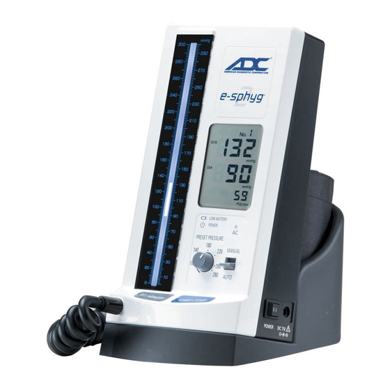
Page 7: Name And Function Of Each Part
Name and function of each part MAIN UNIT SEGMENT LCD COLUMN LCD INFLATION MARK DEFLATION MARK 2mmHg PULSE MARK 1mmHg BATTERY MARK POWER MARK PRESET PRESSURE KNOB START/STOP BUTTON AC INDICATOR SET/MEMORY BUTTON MODE SELECTOR AIR CONNECTOR AIR PLUG BATTERY COMPARTMENT COVER AC ADAPTER JACK... -
Page 8: Name And Function Of Each Part
Name and function of each part Cuff Sizes ADULT LARGE ADULT SMALL ADULT Arm circumferences of 9.0”-15.7” Arm circumferences of 13.3”-19.6” Arm circumferences of 7.4”-10.6” (19.0-27.0cm) (23.0-40.0cm) (34.0-50.0cm) LUER CONNECTOR (Male Luer to Female Blad- BLADDER TUBE der Tube) (Female Luer Connection) COILED TUBING ADCUFF CONNECTOR... -
Page 9: Preparation For Use
Preparation for Use Connecting and Using the AC Adapter (All models) Connect AC ADAPTER PLUG to AC ADAPTER JACK ADAPTER Plug AC ADAPTER in the power socket. PLUG AC INDICATOR is lit when AC ADAPTER is connected correctly. Installing the RECHARGEABLE NiMH Battery (All models) NOTE: The battery enclosed in the product package is not charged, and needs to be charged for about 4 hours before use. - Page 10 BATTERY MARK flashes in the segment LCD when the battery charge is low. Only a few more measurements remain before the battery runs down. The battery needs to be recharged when BATTERY MARK is displayed. Measurement cannot be made. NOTE: The rechargeable batteries may not be completely full after their initial charge or when they have not been used for an extended period of time.
-
Page 11: How To Assemble Wall Model
How to Assemble Wall Model 1. Securely attach wall bracket to flat surface using en- closed mollys and screws at desired height. (It is advised to use a level to ensure proper mounting) . (Figure 1) 2. Attach manometer to wall bracket by lowering a top wall Figure 1 bracket, sliding male tab into female seat of the bracket. -
Page 12: How To Assemble Mobile Model
How to Assemble Mobile Model 1. With base on its side connect upright outer pole to base using large (6mm) allen bolt. Tighten with large (6mm) allen key provided. Tighten hardware as securely as possible. (Note: To prevent loosening, hardware must be tightened securely and periodically checked) (Figure 1). -
Page 13: Cuff Connections
AIR CONNECTOR forefinger,and insert into the air connection port on (Coiled Tubing) the face of the e-sphyg 2 . Make sure connector Figure 1 firmly “lock” snaps into the port (Figure 1). - Page 14 ARM CIRCUMFERENCE CUFF SIZE Apply the cuff to patient's arm. 9.0 to 15.7 inches ADULT (23.0 to 40.0 cm) Choose the right size of cuff for 13.3 to 19.6 inches LARGE ADULT (34.0 to 50.0 cm) your patient. NOTE: Only these 3 cuffs 7.4 to 10.6 inches SMALL ADULT (19.0 to 27.0 cm)
- Page 15 Turn off the device by pressing " " side of MAIN POWER SWITCH. The device will go to the energy saver mode after approximately 3 minutes if it is not turned off. See page 10. Make sure your patient is relaxed, has taken at least 5 minutes of rest before measure- ment and refrains from talking or moving during measurement.
- Page 16 Apply the cuff and stethoscope to the patient's arm in the same manner as the usual auscultatory method. Press START/STOP button. The cuff is inflated automatically after zero settings. Pressurization stops when pressure reaches the preset pressure value and pressure starts to descend. Deflation rate is displayed at the lower right corner of the segment LCD.
-
Page 17: Memory Function
Memory Function Measured result obtained in "AUTO" mode is automatically saved in the memory and can be recalled until next measurement is taken. The result is not saved when the measurement is performed in "MANUAL" mode. To recall the result, turn on the device by pressing "I" side of MAIN POWER SWITCH and set the device to "AUTO"... -
Page 18: Error Displays And Troubleshooting
Error Displays and Troubleshooting ERROR SYMBOL/SYMPTOM CAUSE REMEDY OVER-PRESSURIZATION: Make sure that the patient stays The cuff was inflated to the still during measurement. maximum pressure because of movement of body, etc. MEASUREMENT ERROR: Make sure the patient remains Measurement could not be still and quiet during measure- made because of moving or ment. -
Page 19: Error Displays And Troubleshooting
Error Displays and Troubleshooting ERROR SYMBOL/SYMPTOM CAUSE REMEDY LOW BATTERY: Change the battery. Only a Battery is weak. few measurements can be made before the battery runs down. BATTERY ERROR: Charge the battery. Charge the battery. Measure- ment cannot be conducted. The indication appearing during LCD segment test, which is performed when... - Page 20 Measurement result can- Measurement result is saved Blood pressure was taken not be recalled or is not only when it is taken in “AUTO” in“MANUAL” mode. stored. mode. Measurement cannot be made Cuff inflation does not Battery is exhasted when BATTERY MARK is dis- start.
-
Page 21: Care And Maintenance
Care and Maintenance Because the device includes precision parts, care should be taken to avoid ex- treme temperature variations, humidity, shock, dust, and direct sunlight. Do not drop or strike the device. Make sure not to expose the unit to moisture. This unit is not water resistant. -
Page 22: Wall Unit Parts And Tools
9002W - Wall Unit Parts & Tools ADC Item Item no. e-sphyg 9002 e-sphyg 6mm Allen Wrench 752M-116 Wall Bracket 952-103 Wall Basket with 752M-116 LOW BATTERY POWER PRESET PRESSURE MANUAL (3) screws / (3) mollys 952-025 AUTO Coiled tubing... -
Page 23: Mobile Unit Parts And Tools
9002M - Mobile Unit Parts & Tools ADC Item Item no. e-sphyg 9002 6mm Allen Wrench 752M-116 3mm Allen Wrench 752M-117 e-sphyg 752M-116 Mounting Bolt/Washer (2) 972-101 Mobile Stand 752M-02 LOW BATTERY POWER Coiled tubing 885N PRESET PRESSURE MANUAL AUTO... -
Page 24: Mobile Base Assembly Parts
Mobile Base Assembly Parts ADC Item Item no. ADC Item Item no. 1 Center Pole Screw (1) 6 Spring 972-109 Washer (1) 972-101 6A Gasket, Rubber 972-107A 2 Base 972-080 7 Inner Pole 972-110 3 Casters (5) 972-106 8 Basket Tightening Key... -
Page 25: Specifications
Specifications Operating Principle: Oscillometric method* Indicator: 300 digits column LCD and 10 digits segment LCD Pressure Indicating Range: 0 to 300 mmHg (cuff pressure) Measuring Range: 50 to 250 mmHg (systolic) 40 to 180 mmHg (diastolic) 40 to 160 bpm (pulse rate) Accuracy: ±3 mmHg (cuff pressure) ±5% of reading (pulse rate) -
Page 26: Limited Warranty
4. The manometer is warranted to remain accurate to ±3mmHg over its full range when compared to a reference standard for life. What is Covered: Repair, or replacement of parts, and labor. What is not covered: Transportation charges to and from ADC . Damages caused by abuse, ®... -
Page 27: Replacement Parts
OR SUGGESTIONS CALL TOLL FREE: 1-800-ADC-2670 OR VISIT WWW.ADCTODAY.COM/FEEDBACK Many ADC instruction manuals are available on our website in other languages at www.adctoday.com/care ©2017 ADC ® . All rights reserved. No one is permitted to reproduce or duplicate in any form, this manual or any part thereof without the expressed written permission of ADC ®... -
Page 28: Technical Description
Technical Description The 9002 complies with the EMC, electromagnetic compatibility, standard, IEC60601-1-2. Refer to the tables below for spe- cific information regarding compliance to the standard. The 9002, as a medical electrical equipment, needs special precautions regarding EMC and needs to be installed and put into service according to the EMC information provided below. - Page 29 Table 4 - Guidance and manufacturer’s declaration - electromagnetic immunity - The 9002 is intended for use in the electromagnetic environment specified below. The customer or the user of the 9002 should assure that it is used in such an environment. Compliance level Immunity test IEC 60601 test level...
- Page 30 Inspected, Assembled and Packaged in the U.S.A. Made in Japan 55 Commerce Drive tel: 631-273-9600, 1-800-232-2670 Hauppauge, NY 11788 www adctoday com fax: 631-273-9659 U.S.A. email: info@adctoday.com IB p/n 93-9002-00 rev 11 Printed in Japan A114487-1_7...
Need help?
Do you have a question about the e-sphyg 2 and is the answer not in the manual?
Questions and answers