
Related Manuals for Hisense AMS-09UR4SNZA2


Summary of Contents for Hisense AMS-09UR4SNZA2
-
Page 1: Service Manual
MULTI-SPLIT TYPE AIR CONDITONER SERVICE MANUAL V: 2.0 ● INDOOR UNIT: AMS-09UR4SNZA2 AMS-12UR4SNZA2 ● INDOOR UNIT: AMW2-20U4SKB AMW3-24U4SKB AMW4-28U4SKB Hisense Corporation... -
Page 2: Table Of Contents
Table of contents Page 1.OPERATING RANGE 2.SPECIFICATION 2-1 Unit specifications 2-2 Major component specifications 2-3 Other component specifications 3.OUTLINES AND DIMENSIONS 3-1 INDOOR 3-2 OUTDOOR 4.REFRIGERANT FLOW DIAGRAM 4-1 Refrigerant flow diagram 4-2 Evacuation procedures 4-3 Evacuation direction 5.ELECTRICAL DATA 5-1 Electric wiring diagrams 5-2 Electric control 5-3 Sensor parameter... -
Page 3: 1.Operating Range
Temperature Indoor Air Intake Temp. Outdoor Air Intake Temp 43 ℃ D.B./26℃ W.B. COOLING Maximum 32℃ D.B./23℃ W.B. 21 ℃ D.B./15℃ W.B. Minimum 21℃ D.B./15℃ W.B. 27℃ D.B./18℃ W.B. 24℃ D.B./18℃ W.B. HEATING Maximum Minimum 20℃ D.B/≤15℃ W.B -7℃ D.B./-8℃ W.B. -
Page 4: 2.Specification
2-1. Unit specifications 2-1-1.OUTDOOR UNIT Model AMW3-24U4SKB AMW4-28U4SKB AMW2-20U4SNB Function Cooling Heating Cooling Heating Cooling Heating Power supply a.c 220V~230V/50Hz Capacity l /h Dehumidification ---- ---- ---- ---- ---- ---- Capacity Air flow ---- ---- ---- ---- ---- ---- Rated current 10.7 10.7 11.1... - Page 5 2-1-2.INDOOR UNIT Model AMS-09UR4SNZA2 AMS-12UR4SNZA2 Function Cooling Heating Cooling Heating Power supply a.c 220V~230V/50Hz Capacity Dehumidification l /h ---- Capacity Air flow m3/h Running current 0.18 0.18 0.18 0.18 Rated input Electrical data Auxiliary heater ---- Power factor ---- Starting current...
-
Page 6: Major Component Specifications
2-2. Major component specifications 2-2-1.INDOOR FAN MOTOR ELECTRIC PARAMETER PERFORMANCE AMS-09UR4SNZA2 AMS-12UR4SNZA2 Motor model YYW16-4-532 YYW16-4-532 Rated power source 220V 50Hz 220V 50Hz Phases/Poles Rated load output(W) Rated speed(r/min) Ambient -5℃~+43℃. -5℃~+43℃. temperature(℃) 2-2-2 OUTDOOR FAN MOTOR ELECTRIC PARAMETER PERFORMANCE... -
Page 7: Other Component Specifications
AC 220V—50Hz Filter frequency 150K—30MHHz 150K—30MHHz range Temperature -25℃~+85℃. -25℃~+85℃. range(℃) 2-3-4. STEPPER MOTOR ELECTRIC PARAMETER PERFORMANCE AMS-09UR4SNZA2 AMS-12UR4SNZA2 Stepper Motor model 24BYJ48-CP 24BYJ48-CP Voltage(DC) Number of phase Drive mode 1-2phase excitation 1-2phase excitation unipolar drive unipolar drive Resistance per phase 300Ω±7%... -
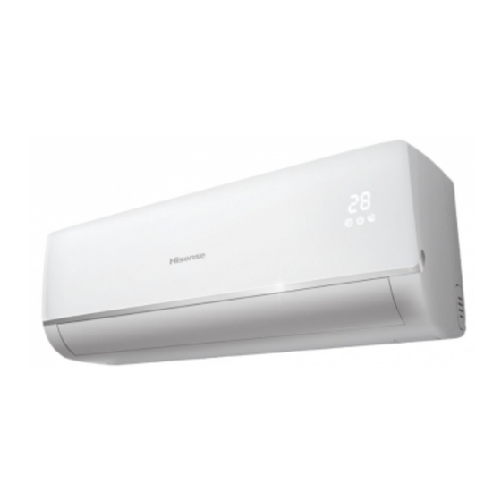
Page 8: 3.Outlines And Dimensions
3-1. INDOOR(MODEL: AMS-09UR4SNZA2、AMS-12UR4SNZA2) 190mm 750mm 65mm 94mm 631mm 23mm 50mm 50mm... -
Page 9: Outdoor
3-2.OUTDOOR(MODEL: AMW2-20U4SNB)... - Page 10 3-3.OUTDOOR(MODEL: AMW3-24U4SKB、AMW4-28U4SKB)...
-
Page 11: 4.Refrigerant Flow Diagram
Refrigerant flow diagram : 4-1. MODEL:AMW3-24U4SKB、AMW4-28U4SKB A机 B机 C机 D机 D机 C机 B机 Filter A机 Remark: The part is only for AMW4-28U4SKB COOLING CYCLE HEATING CYCLE... - Page 12 MODEL:AMW2-20U4SNB 4-way valve A 机 B 机 B 机 Filter EEV B A 机 Filter EEV A...
-
Page 13: Evacuation Procedures
4-2. Evacuation procedures: EVACUATION PROCEDURES Connect the refrigerant pipes (both the liquid and gas pipes) between the indoor and the outdoor units. Remove service port cap of the stop valve A and connect gage manifold valve and vacuum pump to it. Run the vacuum pump for more than 15 minutes and at this time confirm that the pressure gage indicates -0.1Mpa(-76 cmHg). -
Page 14: Evacuation Direction
4-3. Evacuation direction: MAX. Refrigerant pipe length and height difference: AMW3-24U4SKB Modle AMW2-20U4SNB AMW4-28U4SKB Pipe length per. Indoor unit(a/b/c/d) Total pipe length for multi-system (a+b+c+d) Height difference (I.D ~ O.D) Height difference (I.D ~ I.D) 7.5m 7.5m *Do your best to reduce the pipe length. Long pipe may cause capacity of the indoor unit incline. Total refrigerant pipe length Outdoor unit precharged 0m~20m... -
Page 15: 5.Electrical Data
5-1.Electrical wiring diagrams INDOOR:AMS-09UR4SNZA2、AMS-12UR4SNZA2 OUTDOOR: 1)AMW4-28U4SKB POWER TERMINAL PANEL ELECTRIC WIRING DIAGRAM 1(L) FUSE 2(N) 1310785 3( ) COMPRESSOR 4-WAY VALVE FAN MOTOR YLW/GRN AUXILIARY HEATER CAPACITOR CONNECTION TERMINAL PANEL D 1(L) 2(N) CN6 VA BLK CN7 FM WHT RECTIFYING... - Page 16 2)AMW3-24U4SKB: ELECTRIC WIRING DIAGRAM 1310435 POWER COMPRESSOR TERMINAL 4-WAY VALVE FAN MOTOR PANEL AUXILIARY HEATER CAPACITOR 1(L) FUSE 2(N) 3( ) YLW/GRN CN6 VA BLK CN7 FM WHT RECTIFYING BRIDGE POWER FILTER BOARD CONNECTION FILTER TERMINAL PANEL C CN8 WHT ELECTROLYTIC 1(L) 9 10...
-
Page 17: Electric Control
5-2. Electric control 1. Control board for indoor unit(AMS-09UR4SNZA2、AMS-12UR4SNZA2)... - Page 18 2. Control board for outdoor unit(AMW3-24U4SKB、AMW4-28U4SKB) 1)FILTER BOARD 3.15 /250 2)CONTROL BOARD...
- Page 19 3. Control board for outdoor unit(AMW2-20U4SNB) 1)FILTER BOARD 2)CONTROL BOARD...
-
Page 20: Sensor Parameter
5-3. Sensor parameter 1. THE PARAMETER OF OUTDOOR COMPRESSOR TEMPERATURE SENSOR: (R =187.25K±6.3%;R =3.77K±2.5K;B=3979±1%) T(℃ ) R(KΩ ) V(v) T(℃ ) R(KΩ ) V(v) T(℃ ) R(KΩ ) V(v) 966.1 0.1014 55.46 1.3252 6.662 3.7507 910.3 0.1075 53.11 1.3678 6.446 3.7813 0.1139 50.86... - Page 21 2. THE PARAMETER OF THE OTHER SENSOR IN INDOOR AND OUTDOOR UNIT: (R =15K±2%;B=3450±2%) T(℃) R(KΩ) V(v) T(℃) R(KΩ) V(v) T(℃) R(KΩ) V(v) 67.94 0.3235 6.962 2.0151 1.297 3.9186 64.25 0.3408 6.688 2.0636 1.258 3.9443 60.79 0.3588 6.427 2.1120 1.22 3.9696 57.53 0.3776...
-
Page 22: 6.Control Mode
INDOOR CONTROL MODE(AMS-09UR4SNZA2、AMS-12UR4SNZA2) 1.Major general technical parameters 1 Conditionings for operation: Ambient temperatures: (-15 - +45 ℃), relative humidity (45 - 85%). 2 Remote receiver distance: 8 m. 3 Remote receiver angle: Less than 80 degrees. 4 Temperature control accuracy: ±1℃. - Page 23 command of such a remote signal. 3.2 Operator-machine communication 1. The air conditioner has a thermal sensor to detect room temperatures. Some remote controller is equipped with a thermal sensor (Such remote controller has the function of man-machine communication. For details, refer to the section for the remote controller). In addition, there is a thermal sensor at the indoor air inlet.
- Page 24 frequency displayed on the screen is up to the maximum. It will restore to the previous run state after 15 minutes operation automatically. 3.6 Automatic run mode If there is no man-machine communication function after the unit is started, the indoor fan operates at the ultra-low fan speed for 20 seconds before selecting a run mode.
- Page 25 3.8 Flap control The flap opens to the position as shown in the figure below: ⑥ ⑤ ④ ③ ② ① 1. When set to open to one of the positions 1 – 6 as shown in the figure above, it is fixed in the corresponding position.
- Page 26 Note: The longest time is 4 minutes from the compressor starts to the cold air protection end., after this fan speed is according to setting fan speed. 3.10 Residual heat blowing off When shut off indoor unit , for evaporator is still hot, the fan may still work for a while to blow the temperature down, when the temperature of evaporator is low enough, the fan will stop, and the flap will be closed automatically.
-
Page 27: Outdoor Control Mode
Outdoor mode control (AMW3-24U4SKB、AMW4-28U4SKB、AMW2-20U4SNB) 1. Summarization This direction applies to multi-type and DC variable frequency air conditioner 2. Performance index 1. Voltage scale: 175~253VAC 50Hz 2. Storage temperature scale: -40℃~85℃ 3. Storage humidity scale: PH30%~PH95% 4. Working temperature:-20℃~85℃ 5. accuracy for temperature control: ±0.5℃ 3.Control function Cooling Anti-freeze Protection To prevent freezing caused by too low temperature of indoor evaporator, the air conditioner will... - Page 28 Current Protection To prevent abnormal, The soft may control machine’s current at a reasonable level in accordance with indoor/outdoor temperature and the demand of the total capacity, Enter the current protection UP-LIMIT control when the current is higher than "Up -limit-frequency value"...
- Page 29 DSH control will be taken in cooling mode. DSH = discharge temperature - condenser coil temperature. SSH control will be taken in heating mode. SSH = suction temperature –coil temperature of outdoor exchanger. During the system operation, soft will calculate DSH and SSH in a real-time: When the DSH or SSH deviates from normal range, the soft will interfere with the normal expansion valve control and amend the expansion valve opening to return DSH or SSH to normal range.
- Page 30 If the indoor temperature is 1℃ lower than the set value, the temperature on operation is allowed; if the indoor temperature is 1℃ higher than the set value, temperature off operation will be taken.(The indoor unit can’t turn off within 5 minutes after switching on). Outdoor four-way Valve Control Four-way valve of the outdoor machine shuts down when cooling but starts when heating.
- Page 31 Fault code 1: If the unit reports the following fault code, compressor will stops, and the unit can’t be operated until the failure is eliminated: Communication fault with IPM Suction sensor fault Discharge sensor fault Top of the compressor sensor fault Outdoor coil temperature sensor fault Defrosting sensor fault Outdoor temperature sensor fault...
- Page 32 Fault code 2: if the unit reports the following fault code, the indoor unit which fault will be seen as shutdown, while other indoor units can operate normally. A Communication Fault B Communication Fault C Communication Fault D Communication Fault EEPROM of outdoor unit fault (the unit will operate in accordance with the default value) Freeze protection or high-temperature protection of indoor unit A.
-
Page 33: 7.Troubleshooting
7-1. Trouble alarm 7-1-1.To display error code(AMS-09UR4SNZA2、AMS-12UR4SNZA2): When error occurred, error code can be displayed on the screen of indoor unit through remoter or emergency switch. To display the error code, refer to the following: Usage1:press “high power” button(or “H.P” button) on remote controller for 5 times. - Page 34 valve is blocked. e) Freon is leaking. Emergency shutdown for current a) Normal protection overload. b) The outdoor board in trouble. Indoor unit A boot fault for freeze a) Expand valve A is damaged (leaking). protection b) The coil temperature sensor in indoor unit A is fault.
-
Page 35: 8.Checking Components
8-1. Check refrigerant system TEST SYSTEM FLOW Conditions: ① Compressor is running. ② The air condition should be installed in good ventilation. Tool: Pressure Gauge Technique: ① see ② feel ③ test ----- Tube defrost. FEEL ----- The difference between tube’s temperature. TEST ----- Test pressure. - Page 36 Test system flow Cooling mode Test system The pressure on the pressure.Does the low high side. pressure normal at service part ? Recharge refrigerant after air purging with If the pressure is The pressure on the the vacuum close to static low side.
-
Page 37: Check Parts Unit
8-2.Check parts unit 1. INDOOR FAN MOTOR( -116-) .MOTOR EXAMINE AND REPAIR Circuit diagram BROWN BLACK WINDING " " YELLOW M The main winding " " A The auxiliary winding BLACK Vout WHITE Capacitor ℃ Hot protector 100 Test in resistance. TOOL: Multimeter. - Page 38 OUTDOOR FAN MOTOR(1323471) Winding BROWN "M"-The Main Winding "A"-The Auxiliary Winding Capacitor Hot Protector 130℃ WHITE PINK PURPLE YELLOW Winding resistance ( at 20℃) M: 185Ω A: 200Ω Test in resistance. TOOL: Multimeter. Test the resistance of the main winding. The outdoor fan motor is fault if the resistance of main winding 0(short circuit)or∞(open circuit).
- Page 39 Don’t place the comp. In air for along time. 3)Avoiding compressor running in reverse caused by connecting electrical wire incorrectly. 4)Warning! In case AC voltage is impressed to compressor, the compressor performance will below because of its rotor magnetic force decreasing. 4.
- Page 40 7.CAPACITOR 1) Remove the lead wires from the capacitor terminals, and then place a probe on the capacitor terminals as shown in Fig.3. 2) Observe the deflection of the pointer, setting the resistance measuring range of the multimeter to the maximum value. * The capacitor is “good”...
-
Page 41: 9.Parts List
9-1. Indoor(AMS-09UR4SNZA2、AMS-12UR4SNZA2) 1 7 1 1 7 4 1 7 3 1 7 2... - Page 42 1204031 FIXED BOARD RZA-2-2362-032-XX-0 1203639 INSTALLATION PLATE 1203356 RZA-2-2230-114-XX-0 RZA-0-0054-145-XX-0 REMOTE CONTROLLER 1301993 ELECTRICAL CONTROL BOX 1203207 RZA-0-5315-023-XX-0 COVER AMS-09UR4SNZA2 K36411463 1337685 CONTROL BOARD ASS'Y AMS-12UR4SNZA2 1313260 K36410157 RZA-2-5307-051-01-1 ELECTRICAL CONTROL BOX 1203964 CLIP 1203961 RZA-2-5304-016-01-2 TERMINAL BOARD ASS'Y 4-2379-123-02-0...
-
Page 43: Outdoor
9-2. Outdoor (AMW3-24U4SKB、AMW4-28U4SKB) 9-2-1. Parts 1. Configuration parts Yellow Green Blue Black White Yellow T-dis... - Page 44 2. System parts...
- Page 45 9-2-2. List KEY NO. PART CODE PART NO. DESCRIPTION Q'TY NOTE 1202500 RZA-0-1321-003-XX-0 FAN GUARD ASSY 1202383 RZA-2-1112-004-XX-0 AMW3-24U4SKB FRONT PANEL 1312026 K31470022 AMW4-28U4SKB 1202381 RZA-0-1112-005-XX-0 RIGHT PANEL ASSY 1202703 RZA-2-2303-001-XX-0 HANDLE 1202610 RZA-2-2228-002-XX-0 DRAINAGE HOSE 1301625 RZA-0-2202-254-XX-0 AMW3-24U4SKB BASE ASSY 1312062 K31120001 AMW4-28U4SKB...
- Page 46 1301839 4-5259-390-04-0 TEMPERATYRE SENSOR 1301832 4-5259-390-02-0 TEMPERATYRE SENSOR 1301833 4-5259-390-03-0 TEMPERATYRE SENSOR 1301841 4-5259-390-05-0 TEMPERATYRE SENSOR 1301842 4-5259-290-01-0 TEMPERATYRE SENSOR 1300307 RZA-0-4519-021-XX-0 ELECTRONIC EXPANSION VALVE 1300208 RZA-2-4221-623-XX-0 1/4 TUBE 1302908 RZA-0-4515-00B-42-0 1/4' SERVICE VALVE 1203230 RZA-2-2475-017-XX-0 INSULATION CUSHION 1300204 RZA-0-4206-982-XX-0 STAINER ASS’Y 1302912 RZA-0-4518-00B-42-0...
- Page 47 1304193 RZA-0-5306-027-XX-1 TERMINAL PANEL Note: * For AMW3-24U4SKB, the quantity is 3 instead of 4 ** For AMW3-24U4SKB, the quantity is 4 instead of 5 *** The item is only for AMW4-26U4SKB.
- Page 48 9-3. Outdoor (AMW2-20U4SNB)...
- Page 49 KEY NO. PART CODE PART NO. DESCRIPTION Q'TY NOTE 1202499 RZA-2-1321-002-XX-0 FAN GUARD K31470066 8004546 FRONT PANEL K38310006 1324263 PROPELLER FAN K1B310044 1323471 FAN MOTOR ASSY K331F0030 1333872 FAN MOTOR SUPPORTER 1327595 K37340102 CONDENSER ASSY K31220010 8004547 BACK PANEL 1202470 RZA-0-5302-003-XX-0 SIDE COVER ASSY 1206659...
Need help?
Do you have a question about the AMS-09UR4SNZA2 and is the answer not in the manual?
Questions and answers