Mitsubishi FX1N Series User Manual
Hide thumbs
Also See for FX1N Series:
- User manual (3 pages) ,
- Programming manual (466 pages) ,
- Hardware manual (94 pages)
Table of Contents
Advertisement
Quick Links
This manual contains text, diagrams and explanations which will guide the reader in the correct
Installation, safe use and operation of the FX
read and understood before attempting to install or use the unit. Further information can be found in the
associated manuals list below.
Specifications are subject to change without notice
Guidelines for the Safety of the User and Protection of the
FX
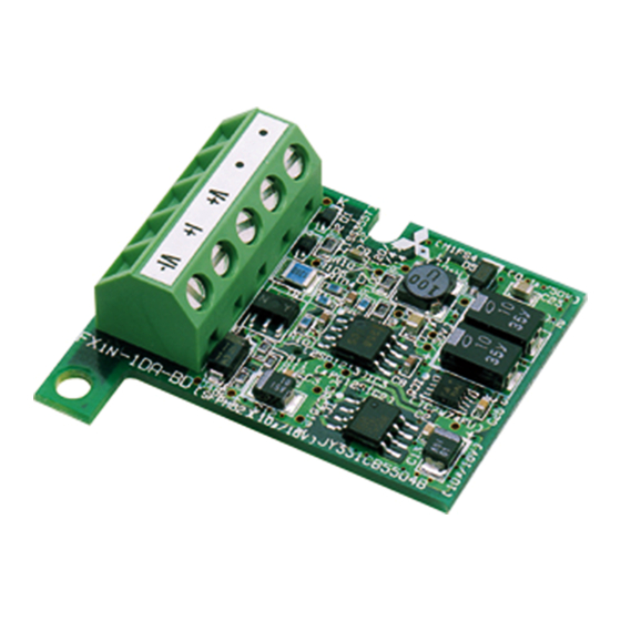
-1DA-BD Analog Output Expansion Board.
1N
This manual has been written to be used by trained and competent personnel. The definition of such a
person or persons is as follows:
a) Any engineer using the product associated with this manual, should be of a competent nature,
trained and qualified to the local and national standards. These engineers should be fully aware of
all aspects of safety with regards to automated equipment.
b) Any commissioning or service engineer must be of a competent nature, trained and qualified to
the local and national standards.
c) All operators of the completed equipment should be trained to use that product in a safe and
coordinated manner in compliance to established safety practices.
Note: The term 'completed equipment' refers to a third party constructed device which contains or uses
the product associated with this manual.
Note's on the Symbols Used in this Manual
At various times through out this manual certain symbols will be used to highlight points of information
which are intended to ensure the users personal safety and protect the integrity of equipment.
1) Indicates that the identified danger WILL cause physical and property damage.
2) Indicates that the identified danger could POSSIBLY cause physical and property
damage.
•
Under no circumstances will Mitsubishi Electric be liable or responsible for any consequential damage
that may arise as a result of the installation or use of this equipment.
•
All examples and diagrams shown in this manual are intended only as an aid to understanding the
text, not to guarantee operation. Mitsubishi Electric will accept no responsibility for actual use of the
product based on these illustrative examples.
•
Owing to the very great variety in possible application of this equipment, you must satisfy yourself as
to its suitability for your specific application.
Associated Manual
Manual Name
FX
Series
1S
Programmable controllers
Hardware Manual
FX
Series
1N
Programmable controllers
Hardware Manual
FX Series of
!
Programmable controllers
Programming Manual ΙΙ
! Indispensable manual
FX
-1DA-BD Analog Output Expansion Board
1N
-1DA-BD Analog Output Expansion Board and should be
1N
Manual
Number
Describes contents related to hardware of FX
JY992D83901
Series PLC, such as specifications, wiring and
installation.
Describes contents related to hardware of FX
JY992D89301
Series PLC, such as specifications, wiring and
installation.
Describes instructions in FX
JY992D88101
series.
User's Manual
JY992D96401B
Description
/FX
1S
1S
1N
/FX
/FX
1N
2N
2NC
Advertisement
Table of Contents

Related Manuals for Mitsubishi FX1N Series


Summary of Contents for Mitsubishi FX1N Series
- Page 1 • All examples and diagrams shown in this manual are intended only as an aid to understanding the text, not to guarantee operation. Mitsubishi Electric will accept no responsibility for actual use of the product based on these illustrative examples.
- Page 2 1. Introduction The FX -1DA-BD analog output expansion board (hereafter called “1DA” or “expansion board”) is to be installed in an FX or FX series PLC, to increase the analog output by 1 point. 1.1 Features of 1DA 1) Analog output of 1 point can be increased using 1DA. If a 1DA is used, internal mounting in the top of the PLC means there is no need for a change to the installation area of the PLC.
- Page 3 2.3 Performance Specifications Table 2.1: Performance Specifications Specification Item Voltage output Current output Range of analog DC 0 ~ 10V DC 4 ~ 20mA output (External load resistance 2k ~ 1MΩ) (External load resistance 500Ω or less) Digital output 12bit binary Resolution 2.5mV (10V /4000) 8µA {(20mA - 4mA) /2000}...
- Page 4 4. Wiring Caution: Cut off all phases of power source before installing / removing or performing wiring work on the expansion board in order to avoid electric shock or damage of product. Note: • Do not lay signal cable near to high voltage power cable or house them in the same trunking duct.
- Page 5 5. Example Program An analog output is converted from a digital value (D8114) using the DA conversion characteristic specified by special auxiliary relay M8114 at each END instruction. 5.1 Allocated Device Table 5.1: Allocation of Device Device Description Switch of output mode M8114 OFF: Voltage output mode (0 ~ 10V)
- Page 6 The value of D60 is given as a multiple of five M8000 M8114 FNC 23 FNC 12 D8114 Manual number : JY992D96401 Manual revision : B Date : JULY 2004 HEAD OFFICE : MITSUBISHI DENKI BLDG MARUNOUTI TOKYO 100-8310 HIMEJI WORKS : 840, CHIYODA CHO, HIMEJI, JAPAN...
- Page 7 • After the installation and wiring etc. replace the PLCs top cover before power ON. Table 1.3: Applicable Programmable Controller text, not to guarantee operation. Mitsubishi Electric will accept no responsibility for actual use of the Note: PLC Type Applicable version product based on these illustrative examples.
- Page 8 The original range of the analog output is not changed. M8000 M8114 FNC 23 FNC 12 D8114 Manual number : JY992D96401 Manual revision : B Date : JULY 2004 HEAD OFFICE : MITSUBISHI DENKI BLDG MARUNOUTI TOKYO 100-8310 HIMEJI WORKS : 840, CHIYODA CHO, HIMEJI, JAPAN...
Need help?
Do you have a question about the FX1N Series and is the answer not in the manual?
Questions and answers