Table of Contents
Advertisement
Available languages
Available languages
Quick Links
Rettungswegtechnik
Escape route technology
m
T A
U
F
t i
v
Bedientableau 925-Touch
925-Touch control panel
Installationsanleitung
Installation manual
D0151500
t a
t u
s ´
S t
a t
i o
n
1 ´
e s
G
p
e r
r t
I n
a k
t i
v
T u
e r
A l
2
a r
h r
U
1 3
8 5
N
O
I n
a k
t i
v
a r
A l
m
U
I n
h r
a k
1 3
8 5
N
T A
O
F
U
E
M
A
A l
a r
m
A
i v
k t
1 3
8 5
N
O
T A
U
F
S c
h l
e u
s e
T ü
r s
a r
A l
m
I n
a k
t i
v
1 3
8 5
N
T A
O
F
U
h r
U
I n
a k
t i
v
G
e s
e r
p
r t
E
A
M
T u
e r
2
G
e s
p
e r
r t
A
i v
k t
T u
e r
2
S c
h l
e u
s e
www.assaabloy.com/de
DE Seite
EN Page
2
36
Advertisement
Chapters
Table of Contents

Related Manuals for Assa Abloy effeff 925


Summary of Contents for Assa Abloy effeff 925
- Page 1 Rettungswegtechnik Escape route technology www.assaabloy.com/de DE Seite EN Page T ü s ´ 1 ´ Bedientableau 925-Touch 925-Touch control panel Installationsanleitung Installation manual D0151500...
- Page 2 D0151500 08.2023 Copyright © 2023, ASSA ABLOY Sicherheitstechnik GmbH Diese Dokumentation einschließlich aller ihrer Teile ist urheberrechtlich geschützt. Jede Verwertung bzw. Veränderung außerhalb der engen Grenzen des Urheberrechtsgeset zes ist ohne Zustimmung von ASSA ABLOY Sicherheitstechnik GmbH unzulässig und strafbar.
-
Page 3: Table Of Contents
Inhaltsverzeichnis Produktinformation........4 Bedientableau 925-Touch........... . . 4 Hinweise . -
Page 4: Produktinformation
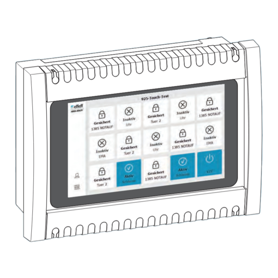
Produktinformation Bedientableau 925-Touch Das Bedientableau 925-Touch dient als zentrale Bedien- und Anzeigeeinheit für maximal 24 Türen mit Fluchttürsteuerungen und TS-Busvernetzung. Das integrierte Touch-Display dient zur Statusanzeige und Steuerung von Türen und Gruppenfunktionen. (Abb. 1) Es ist in Kombination mit dem TS-Bus-Controller 970-TSBC-30 ab Version 5.13.0604 TS-Bus-Controller einsetzbar (separate Anleitung D01342xx). -
Page 5: Hinweise
Hinweise Zielgruppe Die Montage und Installation des Produkts muss von einer Elektrofachkraft durchgeführt werden, mit von ASSA ABLOY zertifizierter Sachkunde zu Fluchttür- steuerungen gemäß den bauaufsichtlichen Anforderungen an elektrische Verriegelungen von Türen in Rettungswegen. Die Elektrofachkraft ist verpflichtet, die anerkannten Regeln der Technik und Prüfverordnungen der Bundesländer anzuwenden und diesen Kenntnisstand laufend zu aktualisieren. -
Page 6: Sicherheitshinweise
Gefahr durch fehlerhafte Inbetriebnahme: Um die Produktsicherheit zu ge- währleisten, muss die Inbetriebnahme durch eine sachkundige Person durch- geführt werden. ASSA ABLOY Sicherheitstechnik GmbH bietet Schulungen zur Aneignung der erforderlichen Sachkunde an. Gefahr durch fehlerhafte oder nicht durchgeführte Wartung: Die Verantwor- tung für eine korrekte Installation und Funktionskontrolle des Produkts und... - Page 7 Verletzungen führen. Die Montage und Installation des Produkts muss von einer Elektrofachkraft durchgeführt werden, mit von ASSA ABLOY zertifizierter Sachkunde zu Flucht- türsteuerungen gemäß den bauaufsichtlichen Anforderungen an elektrische Verriegelungen von Türen in Rettungswegen. Die Elektrofachkraft ist verpflichtet, die anerkannten Regeln der Technik und Prüfverordnungen der Bundesländer...
-
Page 8: Bestimmungsgemäßer Gebrauch
Abweichende Anwendungen oder in der Zulassung nicht beschriebene Geräte- kombinationen sind unzulässig. Planungshinweise für zulässige Lösungen und die dazu benötigten Gerätekombi- nationen kann ASSA ABLOY Sicherheitstechnik GmbH für Ihre Anwendung gerne bereitstellen. Die Verwendung ist mit den bauaufsichtlichen Anforderungen abzustimmen. Sprechen Sie dazu die zuständige Baubehörde an. -
Page 9: Einsatzszenarien: Einfache Beispiele
Einsatzszenarien: einfache Beispiele Abb. 2: Bedientableau 925-Touch ohne externe Erweiterungen Beispiele für Einsatzszenarien TS-Bus-Controller 970-TSBC-30 Türs tatu s ´Sta tion 1´ TS-Bus Alar m Inak tiv 138 5 NOT Ges per rt Inak tiv Tue r 2 Alar m 138 5 NOT Inak tiv Ges per rt Inak tiv... -
Page 10: Einsatzszenarien: Beispiel Mit Maximal 24 Türen
Einsatzszenarien: Beispiel mit maximal 24 Türen Abb. 3: Beispiele für Konfigurationssoftware Optionale Erweiterung: Einsatzszenarien IO-Interface 901-IO-20 (FT-Manager) In p In p In p In p In p tp u In p tp u In p tp u In p tp u tp u S ta tu s... -
Page 11: Einsatzszenarien: Beispiel Mit Mehr Als 24 Türen
Einsatzszenarien: Beispiel mit mehr als 24 Türen Abb. 4: Beispiele für Konfigurationssoftware Optionale Erweiterung: Einsatzszenarien IO-Interface 901-IO-20 (FT-Manager) In p In p In p In p In p tp u In p tp u In p tp u In p tp u tp u S ta... -
Page 12: Installation
Installation Anschlüsse auf der Platine DIP-Schalterkonsole S1 Nur bei Verwendung mit Hi-O Technology™ IO-Interface 901-IO-20. DIP-Schalter 1 – Hi-O-Bus-Terminierung OFF Bus-Terminierung ist ausgeschaltet ON Bus-Terminierung ist eingeschaltet Bei Verwendung eines IO-Interface 901-IO-20 muss ON eingestellt werden. DIP-Schalter 2 – Hi-O-Gruppe OFF Hi-O-Gruppe 1 Dieselbe Gruppe wie beim angeschlossenen IO-Interface 901-IO-20 einstellen. - Page 13 Klemmleiste J1 Hi-O CAN H Zur optionalen Erweiterung kann an diesem CAN L Hi-O-Technology™-Anschluss maximal ein IO-Interface 901-IO-20 angeschlossen werden. Betriebsspannung Andere Hi-O-Technology™-Komponenten dürfen + 24 V DC SELV nicht angeschlossen werden. TS-Bus TS-Bus-Signal Eingang Eingang Active-low-Input Klemmleiste J2 Ausgang Relais (Wechselrelais) 10 COM max.
-
Page 14: Anschluss Und Inbetriebnahme
Anschluss und Inbetriebnahme Das Bedientableau anschließen Zur Inbetriebnahme muss das Bedientableau 925-Touch geöffnet werden (Abb. 6). Es benötigt zur Inbetriebnahme eine Spannungsversorgung und einen Anschluss an den TS-Bus. Für die Durchführung von Anschlusskabel bietet das Gehäuse mehrere Sollbruch- stellen zum Erstellen von Öffnungen. Lösen Sie die vier Schrauben-Abdeckungen an den Ecken des Frontdeckels. - Page 15 Abb. 6 : Gerät öffnen und Kabel einführen Installation...
- Page 16 Das Bedientableau inbetriebnehmen Die Inbetriebnahme erfolgt immer mit Werkseinstellungen. Falls das Gerät bereits verwendet wurde, kann es in die Werkseinstellungen zurückgesetzt werden („Werkseinstellungen“, Seite 20). Schalten Sie die Versorgungsspannung ein. Das Display zeigt folgende Ansichten in Folge: Berühren Sie , um die Inbetriebnahme zu starten ...
-
Page 17: Update
Update Update durchführen Für das Update liefert ASSA ABLOY eine ZIP-Datei upddef.zip. ZIP-Datei Es wird ein USB-Stick benötigt. upddef.zip Falls der USB-Stick bereits für ein Update verwendet wurde: Löschen Sie die LOG-Datei auf dem USB-Stick. Kopieren Sie die Datei upddef.zip unverändert auf den USB-Stick. -
Page 18: Gerätetest
Gerätetest Das Bedientableau 925-Touch verfügt über einen eigenen integrierten Gerätetest (Abb. 7). Ein Gerätetest kann bei einer Fehlersuche hilfreich sein. Abb. 7 : Gerätetest Installation... - Page 19 Gerätetest starten – vor einer Inbetriebnahme Das Display zeigt das Startbild zur Inbetriebnahme. Berühren Sie das blaue Symbol. Der Gerätetest ist bereit. Gerätetest starten – nach einer Inbetriebnahme Ein Gerätetest kann nur mit Administratorrechten am Bedientableau 925-Touch Administrator- durchgeführt werden. rechte Öffnen Sie den Dialog Geräteeinstellungen über ...
-
Page 20: Werkseinstellungen
Werkseinstellungen Auf Werkseinstellungen zurücksetzen Die Bedienung kann nur mit Administratorrechten am Bedientableau 925-Touch erfolgen. Dazu muss ein TS-Bus-Controller 970-TSBC-30 angeschlossen sein. Öffnen Sie den Dialog Geräteeinstellungen über Der Dialog Geräteeinstellungen wird angezeigt (Abb. 8). Starten Sie den Vorgang. Folgen Sie den Anweisungen auf dem Display. ... -
Page 21: Konfiguration - Über Ft-Manager
Konfiguration – über FT-Manager Die Konfiguration erfolgt über die Web-Oberfläche des FT-Managers (separate Anleitung D01254xx). FT-Manager – Busteilnehmer Nach der erfolgreichen Inbetriebnahme hat das Bedientableau 925-Touch eine Busteilnehmer TS-Busadresse erhalten. Es wird als im FT-Manager unter Systemkonfiguration aufgelistet (Abb. 9 – Abb. -
Page 22: Basisvorgaben
Basisvorgaben In diesem Register werden Informationen zum aktuell ausgewählten Bedientab- leau angezeigt. Es können unter anderem das Erscheinungsbild und die Bedien- freigabe konfiguriert werden. Abb. 10 : Basisvorgaben zum ausgewählten Bedientableau Konfiguration – über FT-Manager... - Page 23 Basisvorgaben konfigurieren Basisvorgaben Klicken Sie auf Wählen Sie in den Pulldown-Menüs das gewünschte Bedientableau bzw. die gewünschte Sortierreihenfolge aus (Abb. 10 – Anzahl Bedienelemente Wählen sie die Anzahl und Anordnung der Bedienelemente aus (– Anzahl: Anordnung: 4 x 2 5 x 3 6 x 4 ...
-
Page 24: Funktionszuordnung
Funktionszuordnung Basisvorgaben In diesem Register können die unter eingestellten Bedienele- mente konfiguriert werden. Zu jedem Bedienelement wird eine Zeile angezeigt. Abb. 11 : Funktions- zuordnungen zu den Bedienelementen Konfiguration – über FT-Manager... - Page 25 Funktionszuordnungen zu Bedienelementen konfigurieren Funktionszuordnung Klicken Sie auf Stellen Sie jeweils die Funktion eines Bedienelementes ein (Abb. 11 – · Bedienung einer Fluchttürsteuerung oder · Bedienung einer Gruppenfunktion Setzen Sie die Optionen ( – · Das unter Funktion zugewiesene Element ist am Bedientableau bedienbar.
-
Page 26: E/A-Konfiguration
E/A-Konfiguration In diesem Register können Ein- und Ausgänge konfiguriert werden. Zur Nutzung der Ein- und Ausgänge müssen diese entsprechend verdrahtet sein („Das Bedientableau anschließen“, Seite 14). Das Bedientableau 925-Touch verfügt intern über einen potentialfreien Eingang und ein Wechselrelais als Ausgang (Abb. 12 – ·... - Page 27 Ein- und Ausgänge konfigurieren E/A-Konfiguration Klicken Sie auf Weisen Sie den Eingängen jeweils eine Funktion zu (Abb. 12 – · keine · BMA (Brandmeldeanlage) · Schaltuhr · Zentralverriegelung · Schlüsselschalter links · Schlüsselschalter rechts · Sabotage Wählen Sie für die Eingänge jeweils eine Funktion aus (Abb. 12 – ·...
-
Page 28: Berechtigungen
Berechtigungen Nach der Funktionszuordnung („Funktionszuordnung“, Seite 24) können Berechtigungen zur Nutzung des Bedientableaus 925-Touch für Nutzer vergeben werden (Abb. 13 – Abb. 13 : Berechtigungen zur Nutzung des Bedientableaus 925-Touch Berechtigungen setzen Klicken Sie auf den jeweiligen Button > in deren Zeile, um die Konfiguration der einzelnen Nutzer aufzurufen. - Page 29 Konfiguration – über FT-Manager...
-
Page 30: Konfiguration - Über Service-Software
Konfiguration – über Service-Software Die Konfiguration eines optional angeschlossenen IO-Interface 901-IO-20 erfolgt über die ePED ® Service Software 1386-Service (separate Anleitung D01112xx) Konfiguration IO-Interface 901-IO-20 Falls ein IO-Interface 901-IO-20 (Abb. 5 Seite 12 – und – ) angeschlossen ist, müssen die Ein- und Ausgänge konfiguriert werden. Eingänge konfigurieren Schließen Sie das IO-Interface 901-IO-20 über das Verbindungskabel ePED ®... - Page 31 Ausgänge konfigurieren Schließen Sie das IO-Interface 901-IO-20 über das Verbindungskabel ePED ® Service Interface USB 1386–SIF an einen PC an. Starten Sie die ePED ® Service Software 1386-Service (Abb. 15). Ausgänge Wechseln Sie auf (– Konfigurieren Sie die Ausgänge wie abgebildet 4.1 Wählen Sie HiO IO Interface für Hutschiene aus (–...
-
Page 32: Technische Daten
175 mm x 240 mm x 90 mm Maximale Anzahl an Türen Schutzart IP 30 Betriebstemperaturbereich 0 – 40°C Betriebsumgebung Innenbereich Zertifizierung ASSA ABLOY Sicherheitstechnik GmbH Werk Albstadt Sicherheitstechnik GmbH EltVTR Bildstockstraße 20 72458 Albstadt DEUTSCHLAND Die EU-Konformitätserklärung finden Sie im Downloadbereich von www.assaabloy.com/de... - Page 33 Gewährleistung, Entsorgung...
-
Page 34: Gewährleistung, Entsorgung
Gewährleistung, Entsorgung Aktuelle Informationen Aktuelle Informationen finden Sie unter: www.assaabloy.com/de Gewährleistung Es gelten die gesetzlichen Gewährleistungsfristen und die Verkaufs- und Lieferbe- dingungen der ASSA ABLOY Sicherheitstechnik GmbH. Entsorgung Für Produkte, die mit dem Symbol (durchgestrichene Mülltonne) gekenn- zeichnet sind gilt: Die geltenden Vorschriften zum Umweltschutz müssen eingehalten werden. - Page 35 Produkt WEEE-Reg.-Nr. DE 69404980 Das Produkt ist nach dem Gebrauch als Elektronikschrott ordnungsgemäß zu entsorgen und zur stofflichen Wiederverwendung einer örtlichen Sammelstelle kostenlos zuzuführen. Es bestehen grundsätzlich folgende weitere Möglichkeiten zur kostenlosen Ent- sorgung beim Vertreiber: · Rückgabe eines funktionsähnlichen Altgeräts am Ort der Abgabe des Neugeräts. ·...
- Page 36 D0151500 08/2023 Copyright © 2023, ASSA ABLOY Sicherheitstechnik GmbH This document and all its parts are copyrighted. Any use or changes outside the strict limits of the copyright are prohibited and liable to prosecution unless prior consent has been obtained from ASSA ABLOY Sicherheitstechnik GmbH.
- Page 37 Table of contents Product information ........38 925-Touch control panel.
-
Page 38: Product Information
Product information 925-Touch control panel The 925-Touch control panel serves as a central operating and display unit for a maximum of 24 doors with escape door control systems and TS bus networking. The built-in touch display is used for status indication and for controlling doors and group functions. -
Page 39: Notices
Target group The assembly and installation of the product must be carried out by a qualified electrician with ASSA ABLOY-certified expertise in escape-door controls in accordance with the building authority requirements for electrical locking of doors in escape routes. The electrician is obliged to observe the recognized rules of technology, test regulations and to update this state of knowledge on an ongoing basis. -
Page 40: Safety Instructions
Danger due to faulty commissioning: In order to ensure the safety of the product, commissioning must be performed by a qualified person. ASSA ABLOY Sicherheitstechnik GmbH offers training for qualification in the requisite skills. Danger due to faulty or improperly performed maintenance: The owner is responsible for correct installation and functional inspection of the product and connected components. - Page 41 The electrician is obliged to observe the recognized rules of technology, test regulations and to update this state of knowledge on an ongoing basis. · Have assembly and installation work carried out by an ASSA ABLOY-certified electrician. Important! Function failure with incorrect operating voltage at the components: A mains adapter according to SELV requirements must be used.
-
Page 42: Intended Use
Different uses or combinations of devices not described in the approval are not permitted. ASSA ABLOY Sicherheitstechnik GmbH can provide the necessary planning informa- tion for approved solutions and the device combinations required for your application. The usage must be coordinated with the requirements of the building inspectorate. -
Page 43: Application Scenarios: Simple Examples
Application scenarios: simple examples Fig. 2: 925-Touch control panel without extensions Examples of application TS bus-controller scenarios 970-TSBC-30 Türs tatu s ´Sta tion 1´ TS bus Alar m Inak tiv 138 5 NOT Ges per rt Inak tiv Tue r 2 Alar m 138 5 NOT Inak tiv... -
Page 44: Application Scenarios: Example With A Maximum Of 24 Doors
Application scenarios: Example with a maximum of 24 doors Fig. 3: Examples of Configuration software Optional Extension: application IO interface 901-IO-20 (FT-Manager) scenarios In p In p In p In p In p tp u In p tp u In p tp u In p tp u... -
Page 45: Application Scenarios: Example With More Than 24 Doors
Application scenarios: Example with more than 24 doors Fig. 4: Examples of Configuration software Optional extension: application IO-Interface 901-IO-20 (FT-Manager) scenarios In p In p In p In p In p tp u In p tp u In p tp u In p tp u tp u... -
Page 46: Installation
Installation Connections on the board DIP switch panel S1 Only when used with Hi-O Technology™ IO interface 901-IO-20. DIP switch 1 – Hi-O bus termination OFF Bus termination is switched off ON Bus termination is switched ON If an IO interface 901-IO-20 is used, ON must be set. DIP switch 2 –... - Page 47 Terminal block J1 Hi-O CAN H For optional extension, a maximum of one CAN L IO-Interface 901-IO-20 can be connected to this Hi-O-Technology™ connection. Operating voltage Other Hi-O-Technology™ components must not +24 V DC SELV be connected. TS bus TS bus signal Input Input Active-low input...
-
Page 48: Connection And Start-Up
Connection and start-up Connecting the control panel For start-up, the 925-Touch control panel must be opened (Fig. 6). It requires a voltage supply and a connection to the TS bus for start-up. The housing has several predetermined breaking points for creating openings for connection cables. - Page 49 Fig. 6 : Open the device and insert the cable Installation...
- Page 50 Starting up the control panel Start-up is always carried out with factory settings. If the device has already been used, it can be reset to the factory settings (“Factory settings”, page 54). Switch on the power supply. The display shows the following views in sequence: Touch to begin start-up ...
-
Page 51: Update
Update Carr ying out an update ASSA ABLOY supplies a ZIP file upddef.ZIP for the update. ZIP file upddef.ZIP A USB stick is required. If the USB stick has already been used for an update: Delete the LOG file on the USB stick. -
Page 52: Device Test
Device test The 925-Touch control panel has its own integrated device test (Fig. 7). A device test can be helpful for troubleshooting. Fig. 7 : Device test Installation... - Page 53 Starting the device test– before a start-up The display shows the start screen for start-up. Touch the blue icon. The device test is ready. Starting the device test– af ter a start-up A device test can only be carried out with administrator rights on the 925-Touch Administrator control panel.
-
Page 54: Factory Settings
Factory settings Resetting to factor y settings Operation can only take place with administrator rights on the 925-Touch control panel. A TS bus controller 970-TSBC-30 must be connected for this. Open the Device settings dialogue via The Device settings dialogue is displayed (Fig. 8). Start the process. -
Page 55: Configuration - Via Ft Manager
Configuration – via FT Manager Configuration is carried out via the FT Manager web interface (separate manual D01254xx). FT Manager – bus participants After successful start-up, the 925-Touch control panel has been given a TS bus bus participant in the FT Manager under System address. -
Page 56: Basic Specifications
Basic specifications Information on the current selected control panel is displayed in this tab. The appearance and the operating release can be configured among other things. Fig. 10 : Basic specifications for the selected control panel Configuration – via FT Manager... - Page 57 Configuring basic specifications Basic specifications Click on Select the desired control panel or sort order in the pull-down menus (Fig. 10 – Number of controls Select the number and view of the controls (– Number: EN 8 EN 15 View: 4 x 2 5 x 3 6 x 4...
-
Page 58: Function Assignment
Function assignment Basic specifications The controls set under can be configured in this tab. One line is displayed for each control. Fig. 11 : Function assignments to the controls Configuration – via FT Manager... - Page 59 Configuring function assignments to controls Function assignment Click Set the function of a control (Fig. 11 – · Operation of an escape door control system or · Operation of a group function Set the options ( – · The control assigned under Function can be operated on the control panel.
-
Page 60: I/O Configuration
I/O configuration Inputs and outputs can be configured in this tab. To use the inputs and outputs, they must be wired accordingly (“Connecting the control panel”, page 48). The 925-Touch control panel has an internal potential-free input and a changeover relay as output (Fig. 12 – ·... - Page 61 Configuring inputs and outputs I/O Configuration Click Assign a function to each input (Fig. 12 – · none · Fire alarm system · Timer switch · Central locking · Key switch, left · Key switch, right · Tampering Select a function for each input (Fig. 12 – ·...
-
Page 62: Authorisations
Authorisations After the function assignment (“Function assignment”, page 58), authorisa- tions to use the 925-Touch control panel can be assigned to users (Fig. 13 – Fig. 13 : Authorisations for using the 925-Touch control panel Assigning authorisations To access the configuration for the individual users, click on the respective button >... - Page 63 Configuration – via FT Manager...
-
Page 64: Configuration - Via Service Software
Configuration – via service software An optionally connected IO interface 901-IO-20 is configured via the ePED ® Service Software 1386-Service (separate manual D01112xx ) Configuration IO interface 901-IO-20 If an IO interface 901-IO-20 (Fig. 5 page 46 – and – ) is connected, the inputs and outputs must be configured. - Page 65 Configuring outputs Connect the IO interface 901-IO-20 to a PC using the ePED ® Service Interface USB 1386–SIF connection cable. Start the ePED ® Service Software 1386-Service (Fig. 15). Outputs Change to (– Configure the outputs as shown 4.1 Select HiO IO interface for DIN top hat rail (– 4.2 Select the outputs (–...
-
Page 66: Technical Data
Maximum number of doors Protection rating IP 30 Operating temperature range 0 – 40°C Operating environment Indoor Certification ASSA ABLOY Sicherheitstechnik GmbH Werk Albstadt Sicherheitstechnik GmbH EltVTR Bildstockstraße 20 72458 Albstadt GERMANY The EU declaration of conformity is available in the download area of www.assaabloy.com/de... - Page 67 Warranty, disposal...
-
Page 68: Warranty, Disposal
Latest information The latest information is available at: www.assaabloy.com/de Warranty The statutory warranty periods and Terms and Conditions of Sale and Delivery of ASSA ABLOY Sicherheitstechnik GmbH.apply. Disposal The following applies to products marked with the symbol (crossed out dustbin): The applicable environmental protection regulations must be observed. - Page 69 Product WEEE reg. no. DE 69404980 You must dispose of the product correctly as electronic scrap after use and take it to a local collection point for recycling free of charge. You have the following additional options for free disposal through the distribu- tor: ·...
- Page 70 Warranty, disposal...
- Page 72 Die ASSA ABLOY Gruppe ist der Weltmarktführer in Zugangslösungen. Jeden Tag helfen wir Menschen sich sicherer und geborgener zu fühlen und eine offenere Welt zu erleben. ASSA ABLOY Sicherheitstechnik GmbH Bildstockstraße 20 72458 Albstadt DEUTSCHLAND Tel. + 49 7431 123-0 albstadt @ assaabloy.com...
Need help?
Do you have a question about the effeff 925 and is the answer not in the manual?
Questions and answers