Table of Contents
Advertisement
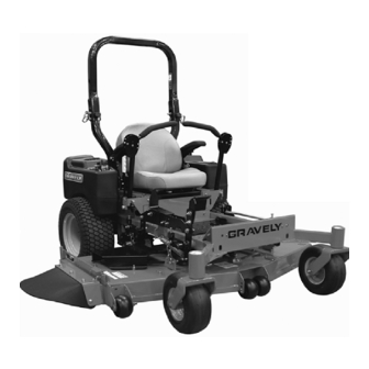
Pro-Turn
Owner/Operator Manual
Manuel Du Propriétaire/Utilisateur
E10
™
The use of any gasoline exceeding 10% ethanol (E10) or
10% MTBE will void the product warranty.
L'utilisation d'une essence contenant plus de 10% d'éthanol
(E10) ou de 10% de MTBE annulent la garantie.
ENGLISH
FRANÇAIS
Models
991200 – Pro-Turn 48
(SN 020000 +)
991201 – Pro-Turn 52
(SN 020000 +)
991202 – Pro-Turn 60
(SN 020000 +)
991203 – Pro-Turn 60
(SN 020000 +)
991204 – Pro-Turn 48 CARB
(SN 020000 +)
991205 – Pro-Turn 52 CARB
(SN 020000 +)
991206 – Pro-Turn 60 CARB
(SN 020000 +)
04519000A 10/12
Printed in USA
Advertisement
Table of Contents


Need help?
Do you have a question about the Pro-Turn 991200 and is the answer not in the manual?
Questions and answers