
Related Manuals for Gravely COMPACT-PRO 991072


Summary of Contents for Gravely COMPACT-PRO 991072
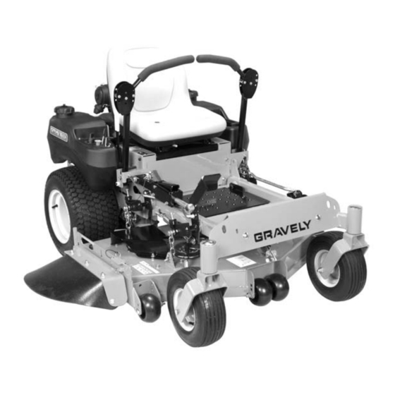
- Page 1 Compact-Pro™ 44 Owner/Operator Manual Manuel Du Propriétaire/Utilisateur 991072 – Compact-Pro 44 ENGLISH FRANÇAIS Models 03993700 11/09 Printed in USA...
-
Page 2: Table Of Contents
NON-ENGLISH MANUALS Manuals in languages other than English may be obtained from your Dealer. Visit your dealer or www.gravely.com for a list of languages available for your equipment. Manuals printed in languages other than English are also available as a free download on our website: http://www.gravely.com... -
Page 3: Product Registration
• Record Engine Model and Serial numbers here. PRODUCT REGISTRATION The Gravely dealer must register the product at the time of purchase. Registering the product will help the company process warranty claims or contact you with the latest service information. All claims meeting... -
Page 4: Safety
WARNING: This cutting machine is capable of amputating hands and feet and throwing objects. Failure to observe the safety instructions in the manuals and on decals could result in serious injury or death. Slopes are a major factor related to loss-of-control and tip-over accidents. - Page 5 1. DANGER! TO AVOID SERIOUS INJURY OR DEATH Read Owner/Operator Manual. OL1801 Keep children and others away from unit while operating. OL4370 Never direct discharge toward other people. Thrown objects can cause injury. Remove objects that could be thrown by the blade.
-
Page 6: Safety Rules
3. WARNING! Do not operate mower unless guards are in operating position or bagger is attached. Always stand clear of discharge area. OL4430 Do not operate mower unless bagger is attached or guards are in operating position. OL3320 4. HOT SURFACES! DO NOT touch parts which are hot from operation. - Page 7 NEVER operate unit after or during the use of medication, drugs or alcohol. Safe operation requires your complete and unimpaired attention at all times. DO NOT wear loose clothing or jewelry and tie back hair that may get caught in rotating parts.
- Page 8 Know the weight of loads. Limit loads to those you can safely control and the unit can safely handle. Disengage PTO when attachment is not in use. ALWAYS turn off power to attachment when travelling, crossing driveways, etc. Mow up and down slopes, not across them. DO NOT operate on slopes of more than 17 degrees.
- Page 9 ALWAYS wear safety glasses and protective gear near battery. Use insulated tools. DO NOT TIP battery beyond a 45° angle in any direction. ALWAYS keep batteries out of reach of children. Battery posts, terminals and related accessories contain lead and lead compounds, chemicals known to the State of California to cause cancer and reproductive harm.
-
Page 10: Unit Assembly
WARNING: AVOID INJURY. Read and understand entire Safety section before proceeding. UNIT ASSEMBLY Package Contents: Unit, Mower Deck and Literature Pack Preparation Checklist Refer to the Owner/Operator manual as required. 1. Unpack Unit - Remove shrink wrap and packaging materials. 2. -
Page 11: Controls And Features
CONTROLS AND FEATURES OM4090 OM4085 OF4035 OF4095 1. Fuel Tanks and Caps 2. Steering Levers 3. Hydraulic Oil Reservoir 4. Ignition Switch 5. Hour Meter 6. Throttle Lever 7. Choke Control 8. Power Take Off (PTO) Switch Figure 4 9. Battery 10. -
Page 12: Operation
Perform the following tests to ensure the safety interlock system is working properly. If the unit does not perform as stated, contact your Gravely dealer for repairs. NOTE: When the parking brake is engaged, the steering levers are locked in neutral. - Page 13 Throttle Lever The throttle lever changes the engine speed. Move the throttle lever to Fast (1) to increase engine speed. Move the lever to Slow (2) to decrease engine speed. OF1700 Bypass Valve Lever Drive Pull the lever back to set the pump in neutral and move the unit with the engine off.
-
Page 14: Filling Fuel Tank
The alert starts counting down two hours before the maintenance is due. The meter flashes the word, "Now," when it reaches the maintenance time. Press and hold the toggle button to reset the maintenance clock to zero after perfoming the service. NOTE: The hour meter is preprogrammed for the initial oil change at 25 hours and for 100 hours thereafter. -
Page 15: Stopping In An Emergency
3. Check Engine Fuel and Crankcase Check and add fuel if required. Check that engine crankcase oil is full. Follow Engine Manual Maintenance Schedule. 4. Check Tire Pressure See Specifications on page 31 for correct tire pressure. 5. Check Hydraulic Fluid Level See Check Hydraulic Fluid Level on page 19. -
Page 16: For Best Performance
MOVING THE UNIT WITH THE ENGINE OFF IMPORTANT: Never tow unit. 1. Shut OFF engine. 2. Place seat in the service position (See Service Position on page 18). 3. Pull the right and left bypass levers to the neutral position. WARNING: Do not bypass transmission when on a slope. -
Page 17: Maintenance Schedule
MAINTENANCE SCHEDULE WARNING: AVOID INJURY. Read and understand entire Safety section before proceeding. Period Service Check Safety Interlock Check Parking Brake Interlock System Check Hydraulic Fluid Check Tires Each Clean Unit Proper maintenance can prolong the life of unit. The following charts show the recommended service schedule. -
Page 18: Service Position
Gravely Dealers will provide any service which may be required to keep your unit operating at peak efficiency. Should engine service be required, it can be obtained from a Gravely Dealer or the engine manufacturer’s authorized service center. WARNING: AVOID INJURY. -
Page 19: Change Hydraulic Fluid And Filter
1. Service Position 2. Steering Levers 3. Parking Brake 4. Battery Figure 6 HYDRAULIC FLUID WARNING: HYDRAULIC FLUID can result in severe burns. Fluid in hydraulic system can penetrate skin and result in serious injury or death. Be sure to stop the engine before doing any work on hydraulic parts. -
Page 20: Mower Blades
9. Follow the instructions in To Add Hydraulic Fluid: on page 19. 1. Drain Plug 2. Oil Filter 3. Filter Guard 4. Mounting Hardware Figure 8 Purging the Hydraulic System WARNING: This adjustment requires operating the engine. Use extreme care to avoid contact with moving parts and hot surfaces. - Page 21 Sharpen the Mower Blades CAUTION: DO NOT sharpen mower blades while on unit. An unbalanced mower blade will cause excessive vibration and eventual damage to unit. Check mower blade balance before reinstalling blades. NEVER weld or straighten bent blades. 1. Remove mower blade from unit. Discard mower blade if: •...
-
Page 22: Remove Battery
BATTERY WARNING: AVOID INJURY. Read and understand entire Safety section before proceeding. WARNING: Battery posts, terminals and related accessories contain lead and lead compounds, chemicals known to the State of California to cause cancer and reproductive harm. Wash hands after handling. Unit comes equipped with a maintenance- free battery that requires no regular maintenance except cleaning the terminals. -
Page 23: Jump Starting
3. Connect positive (+) lead of charger to positive (+) terminal, and negative (–) lead to negative (–) terminal. 4. Charge battery according to charger and battery manufacturers’ instructions. 5. Replace battery. See Replace Battery on page 22. Jump-Starting Gravelydoes not recommend jump-starting your unit. -
Page 24: Adjusting The Unit To Track Straight
Aligning the Steering Levers (Figure 14) 1. Shut OFF engine. Engage parking brake. Remove the ignition key. 2. Place seat in the service position (See Service Position on page 18). 3. Loosen brake interlock on the same side as steering lever to be adjusted. 4. -
Page 25: Adjusting The Parking Brake
ADJUSTING THE HEIGHT OF THE STEERING LEVER HANDLES The handles have three height positions (Figure 16). 1. Spacer 3. Eccentric 2. Handle 4. Steering Lever Figure 16 1. Shut OFF engine. Engage parking brake. Remove the ignition key. 2. Remove the spacer, handle, and eccentric spacer from the steering lever. - Page 26 PTO BELT WARNING: MOVING PARTS can cut or amputate body parts. ALWAYS wait for moving parts to stop before performing maintenance or service. CAUTION: DAMAGED OR WORN BELTS may result in injury and/or damage to unit. Check belts for excessive wear or cracks often.
-
Page 27: Anti-Scalp Roller Adjustment
Replacing the Hydro Pump Belt 1. Properly stop and park unit (See Operation on page 12). 2. Remove the PTO belt from the mower clutch sheave (See Replacing Mower Belts on page 26). CAUTION: Use care when releasing idler spring tension. Keep body parts well away from idlers when performing this operation. -
Page 28: Leveling The Mower Deck
Push the mower lift pedal forward between cutting height number 4 and number 5 to align the holes in the deck lift shaft and the deck lift cover. Insert the cutting height pin in the holes on the side of the deck lift cover so it passes all the way through the deck lift cover and shaft. -
Page 29: Clutch Adjustment
NOTE: Pitching the front of the blades lower than the rear provides a balance between cut quality and the power needed to cut grass. Certain cutting conditions require the deck to be pitched with the rear of the blades lower than the front. -
Page 30: Short Term
1. Armature 2. Rotor 3. Inspection Figure 25 Slot STORAGE WARNING: AVOID INJURY. Read and understand entire Safety section before proceeding. SHORT TERM NEVER spray unit with high-pressure water or store unit outdoors. Inspect unit for visible signs of wear, breakage or damage. -
Page 31: Specifications
Model Number Model Engine Engine Model Number Engine Displacement - in3 (cc) Governed RPM (May be different from maximum RPM) Liquid or Air Cooled Speed Forward Maximum – mph (km/h) Reverse Maximum – mph (km/h) Turning Radius Brakes Electrical Starter Battery Power Take-Off Fuel... -
Page 32: Warranty
Genuine Ariens or Gravely brand service parts and accessories are warranted to be free from defects in material and workmanship for a period of 90 days after the date of purchase. An authorized Ariens or Gravely dealer will repair or replace any such part or accessory free of charge, except for labor, during that period. -
Page 33: Exceptions, Limitations, Exclusions
Engines and engine accessories are covered only by the engine manufacturer’s warranty and are not covered by this warranty. • Parts that are not genuine Ariens or Gravely service parts are not covered by this warranty. • The following maintenance, service and replacement items are not covered by this warranty unless... - Page 34 GRAVELY 655 West Ryan Street Brillion, WI 54110-1072 920-756-2141 Fax 920-756-2407 www.gravely.com...
Need help?
Do you have a question about the COMPACT-PRO 991072 and is the answer not in the manual?
Questions and answers