Table of Contents
Advertisement
Quick Links
Advertisement
Table of Contents

Related Manuals for ILX Lightwave LDC-3900


Summary of Contents for ILX Lightwave LDC-3900
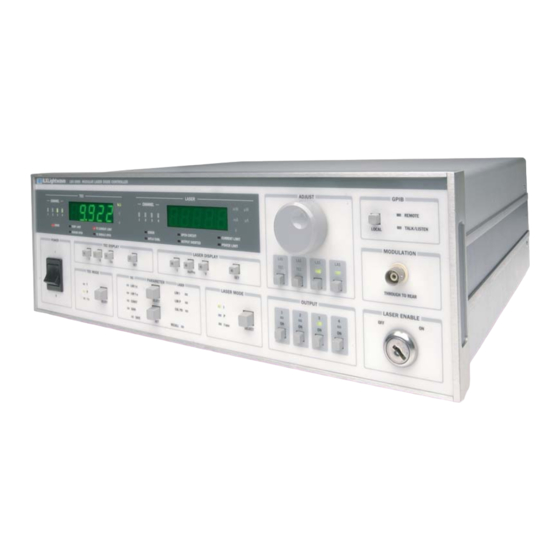
- Page 1 User’s Guide Modular Laser Diode Controller LDC-3900 ILX Lightwave · 31950 Frontage Road · Bozeman, MT, U.S.A. 59715 · U.S. & Canada: 1-800-459-9459 · International Inquiries: 406-556-2481 · Fax 406-586-9405 www.newport.com/ilxlightwave 70011310 October 2015...
-
Page 3: Table Of Contents
Line Voltage Selection ......... . 3 LDC-3900 Series... - Page 4 LDC-3900 Front Panel ........
- Page 5 Default Parameters ..........45 10_15 LDC-3900 Series...
- Page 6 Getting Started with GPIB ......... 46 Overview of the LDC-3900 Syntax ....... . 46 Using Commands with Parameters .
- Page 7 Common Commands ......... . 75 LDC-3900 Device-Dependent Commands ......75 Command Paths .
- Page 8 Table of Contents LDC-3900 Series...
-
Page 9: List Of Figures
Figure 2.1 LDC-3900 Front Panel ....... . 10 Figure 2.2 GPIB Section ........10 Figure 2.3 Laser Enable Switch . - Page 10 Figure 3.12 An LDC-3900 LASER Module Output Off Register ..68 Figure 3.13 An LDC-3900 TEC Module Output Off Register ... 69 Figure 4.1 Command Path Tree Structure .
- Page 11 Table 1.4 General Specifications ........3 Table 2.1 LDC-3900 Default Settings ....... 8 Table 2.2 TEC Error Indicators .
- Page 12 LDC-3900 Series ...
-
Page 13: Safety And Warranty Information
• Prolonged storage under adverse conditions • Failure to perform intended measurements or functions If necessary, return the instrument to ILX Lightwave, or authorized local ILX Lightwave distributor, for service or repair to ensure that safety features are maintained (see the contact information on page xiv). -
Page 14: Safety Symbols
Technical specifications including electrical ratings and weight are included within the manual. See the Table of Contents to locate the specifications and other product information. The following classifications are standard across all ILX Lightwave products: • Indoor use only • Ordinary Protection: This product is NOT protected against the harmful ingress of moisture. -
Page 15: Warranty
Returning an Instrument If an instrument is to be shipped to ILX Lightwave for repair or service, be sure to: Obtain a Return Authorization number (RA) from ILX Customer Service. Attach a tag to the instrument identifying the owner and indicating the required service or repair. -
Page 16: Comments, Suggestions, And Problems
WA R R A N T Y Comments, Suggestions, and Problems To ensure that you get the most out of your ILX Lightwave product, we ask that you direct any product operation or service related questions or comments to ILX Lightwave Customer Support. - Page 17 ILX Lightwave instrument: Description of the problem: If ILX Lightwave determines that a return to the factory is necessary, you are issued a Return Authorization (RA) number. Please mark this number on the outside of the shipping box.
- Page 18 WA R R A N T Y LDC-3900...
-
Page 19: Introduction And Specifications
TEC controller only, and one for functions which pertain to the Laser current source only. Product Overview The LDC-3900 Modular Laser Diode Controller may be configured as a combination current source/temperature controller. It may also be configured with only current sources or only temperature controllers. The current sources provide high stability outputs with fully redundant current limit and multiple laser protection features. -
Page 20: Available Options And Accessories
I N T R O D U C T I O N A N D S P E C I F I C A T I O N S C H A P T E R Product Overview Available Options and Accessories Options and accessories available for the LDC-3900 include the following: Table 1.1 LDC-3900 Options and Accessories DESCRIPTION MODEL NUMBER... -
Page 21: Specifications
C H A P T E R Product Overview Specifications The general specifications for the LDC-3900 are found on page 3. The specifications for each module are found in the instruction manual for that module. Table 1.2 GPIB Specifications Meets ANSI/IEEE Std 488.1-1987 and Std 488.2.2-1987 Table 1.3 General Specifications... - Page 22 I N T R O D U C T I O N A N D S P E C I F I C A T I O N S C H A P T E R Product Overview LDC-3900 Series...
-
Page 23: Chapter 2 Operation
Module installation and removal procedures are described in the module manuals. Note: Modules should be installed or removed from the LDC-3900 only when the power is off. Whenever the modular configuration of the LDC-3900 is changed, the unit will power- up using default parameters. -
Page 24: Tilt-Foot Adjustment
Refer to the laser module manual for details about the interlock function. The LDC-3900 is also equipped with a laser enable key switch. This ensures that the laser current can be turned on only if the key is inserted and in the On position. - Page 25 After this test, the unit is configured to the state it was in when the power was last shut off, unless the LDC-3900 detects that there has been a change in its modular configuration (i.e. a new module added). In that case, the default parameters would be used.
-
Page 26: Table 2.1 Ldc-3900 Default Settings
O P E R A T I O N C H A P T E R Power-Up Sequence Table 2.1 LDC-3900 Default Settings Setting GPIB mode in LOCAL via front panel, or in REMOTE via GPIB TEC output off TEC DISPLAY enabled, in T mode... -
Page 27: Ldc-3900 Front Panel
LDC-3900 Front Panel LDC-3900 Front Panel The LDC-3900 Modular Laser Diode Controller's front panel contains displays and controls for both the TEC and Laser controller hardware. Each of the labeled areas on the front panel (i.e. TEC Display or GPIB) is described in a separate section later in this chapter. -
Page 28: General Functions
O P E R A T I O N C H A P T E R LDC-3900 Front Panel Refer to Figure 2.1 for the following discussions of the LDC-3900 Modular Laser Diode Controller front panel sections. The key words are in bold type for quick identification. -
Page 29: Figure 2.3 Laser Enable Switch
O P E R A T I O N C H A P T E R LDC-3900 Front Panel The Laser Enable switch is used to enable/disable the Laser output. Note - the interlock pins (1 and 2) of the Laser output connector must be shorted also (see module manual for details). -
Page 30: Tec Functions
Figure 2.6 Parameter Section The Save and Recall parameter functions are used to quickly configure the LDC-3900 Modular Laser Diode Controller's parameters to user-determined preset values. In order to use these functions, none of the Adjust modes (TEC and Laser) can be enabled, (Adjust) TEC and (Adjust) Laser Indicators not orange. -
Page 31: Figure 2.7 Tec Mode
O P E R A T I O N C H A P T E R LDC-3900 Front Panel ) control modes. The LED Indicators show the selected mode. (For more information, see TEC Mode Section on page 18). TEC MODE SELECT Figure 2.7 TEC Mode... -
Page 32: Conditions Which Will Automatically Shut Off A Tec Output
O P E R A T I O N C H A P T E R LDC-3900 Front Panel The TEC Display is used to show TEC control (measured and set point) and parameter values. It may also display errors which relate to TEC operation. -
Page 33: Figure 2.11 Laser Mode
O P E R A T I O N C H A P T E R LDC-3900 Front Panel selected mode. Note - not all modes are available with all modules. In that case, only the valid modes may be selected. -
Page 34: Automatic Laser Shutoff Conditions
• Laser mode changes wile the output is on. GPIB Section The GPIB section is located in the top right corner of the LDC-3900 Modular Laser Diode Controller front panel (see Figure 2.1 on page 10). This section contains the LOCAL switch and the REMOTE and TALK/LISTEN indicators. -
Page 35: Adjust Section
GPIB bus. Adjust Section The Adjust section is located on the right side of the LDC-3900 Modular Laser Diode Controller front panel. It consists of the Adjust (main control) Knob and the LAS/TEC adjust mode enable switches. A green (LAS) or (TEC) LED indicates that a corresponding module is available for adjustment. -
Page 36: Output Section
O P E R A T I O N C H A P T E R LDC-3900 Front Panel turned, the TEC display will then show the temperature set point for 3 seconds. After 3 seconds the TEC display will revert to showing the measured R value. -
Page 37: Tec Mode Select
The corresponding (Adjust) TEC indicator must be orange before adjusting the parameters of the TEC Mode functions. Refer to Figure 2.7 on page 13 for the discussion of the features in the TEC Mode section of the LDC-3900 Modular Laser Diode Controller front panel. -
Page 38: Tec Display Set
Refer to Figure 2.8 on page 13 for the discussion of the TEC Display switch section features. TEC DISPLAY Figure 2.17 LDC-3900 TEC Display Switch Section TEC Display Set When the (TEC Display) Set switch is pressed, the (TEC Display) Set switch... -
Page 39: Tec Parameter Section
CAL PD GAIN SAVE RECALL Figure 2.18 LDC-3900 TEC Parameter Section TEC Parameter Select The (Parameter) Select switch is used to enter Select mode. While the (Adjust) TEC Indicator lit is orange, press the (Parameter) Select switch to enter this mode. -
Page 40: Tec Parameter Set
O P E R A T I O N C H A P T E R LDC-3900 Front Panel state continues for three seconds, after which the instrument reverts to its former state. If the (Parameter) Select switch is pressed repeatedly, successive parameter values are displayed, with the appropriate Parameter Setup Indicator LED being lit. -
Page 41: Const
O P E R A T I O N C H A P T E R LDC-3900 Front Panel desired new value is on the TEC display, then release the (Parameter) Set switch. When the (Parameter) Set switch is released, the new value will be stored in non- volatile memory. -
Page 42: Tec Channel Indicators
CHANNEL °C ERROR TEMP LIMIT TE CURRENT LIMIT SENSOR OPEN TE MODULE OPEN Figure 2.19 LDC-3900 TEC Error Section Table 2.2 TEC Error Indicators Error Condition Action Temperature limit TEMP LIMIT light flashes at 1 Hz Open sensor Output off, SENSOR OPEN indicator LED flashes at 1 Hz... -
Page 43: Laser Mode Section
(light power) mode. (For more information on the CAL PD parameter, see CAL PD on page 29). The LDC-3900 Modular Laser Diode Controllers have a special mode for operating at a constant monitor photodiode current when the CAL PD parameter value is set to zero. -
Page 44: Laser Mode Select
(Laser Display) Set Indicator LED will go off (if it was previously on). Refer to Figure 2.12 on page 15 during the discussion of the Laser Display switch section features. LASER DISPLAY Figure 2.21 LDC-3900 Laser Display Switch Section LDC-3900 Series... -
Page 45: Laser Display Set
O P E R A T I O N C H A P T E R LDC-3900 Front Panel Laser Display Set When the (Laser Display) Set switch is pressed, the (Laser Display) Set Switch Indicator and the (Laser Display) Indicator of the set point mode (I or I ) will also become lit, if it is not already lit. -
Page 46: Laser Parameter Section
CAL PD GAIN SAVE RECALL Figure 2.22 LDC-3900 Laser Parameter Section Laser Parameter Select The (Parameter) Select switch is used to enter this Select mode. While the (Adjust) Laser Indicator is orange (Laser mode selected), press the (Parameter) Select switch to enter this mode. -
Page 47: Laser Parameter Set
O P E R A T I O N C H A P T E R LDC-3900 Front Panel Laser Parameter Set The (Parameter) Set switch is used to enter Set mode, where parameter values may be edited and are then stored into non-volatile memory. -
Page 48: Laser Channel Indicators
Laser Error Indicators The functions of the LDC-3900 Modular Laser Diode Controller's Laser error indicators are shown in Table 2.2 on page 24. Refer to Figure 2.23 on page 30 during the discussion of the Laser error indicators. Error codes are explained in Chapter 5, Error Messages. -
Page 49: Modulation Section
MODULATION THROUGH TO REAR Figure 2.24 LDC-3900 MODULATION Section Save and Recall Parameter Functions The Save and Recall parameter functions are used to store and retrieve the LDC- 3900 Modular Laser Diode Controller's parameter configurations for future use. - Page 50 When a parameter setup is saved, the LDC-3900 modular system configuration is also saved in the "bin". Therefore, if a "bin" is to be recalled, the LDC-3900 must have the same configuration. If the present configuration is different than the saved configuration, the LDC-3900 will not perform the Recall function.
-
Page 51: Rear Panel Controls And Connections
REPLACING FUSES. REPLACE FUSES ONLY WITH SPECIFIED TYPE AND RATING. DO NOT REMOVE COVER. REFER SERVICING TO QUALIFIED PERSONNEL. Figure 2.25 LDC-3900 Rear Panel GPIB Connector The GPIB connector is located on the back panel, between the fan and the AC Power Entry Module. -
Page 52: Modulation From Front Connector
(refer to the back panel for the correct ratings). Turn on the LDC-3900. The TEC Output stage(s) will be off at power-up and the unit will automatically configure its parameters to the state which existed when the power was last shut off (if possible). -
Page 53: Laser Mode Operation
The error condition (and all other information) for that TEC channel will be displayed. When the LDC-3900 is powered off, the state of the unit at power-down is saved in non- volatile memory. Calibration data are stored in the individual modules. -
Page 54: Simultaneous Tec And Laser Mode Operation
Output control. TEC Booster Mode Operation You can operate the TEC controller portion of the LDC-3900 Modular Laser Diode Controller with an external TEC current source (booster). Operation is the same as described in TEC Mode Operation on page 34, except that when a booster is present a control signal of +10.0 volts is used to drive the external TEC current... -
Page 55: Remote Operation
This chapter is divided into three parts. The first part has the information for using the GPIB with the LDC-3900 Modular Laser Diode Controller. It also has sections for each common GPIB (ANSI/IEEE-488.2) command which is supported by the LDC-3900 Modular Laser Diode Controller. -
Page 56: Preparation For Bus Control
Preparation for Bus Control To use the LDC-3900 Modular Laser Diode Controller remotely, you will need to install an IEEE-488 interface adapter in your host computer. These adapters and support software are available from several manufacturers and can be installed in most computers. -
Page 57: White Space
In most practical programming situations, the space character (space bar) would be used as white space. White space is generally used for separating other 10_15 LDC-3900 Series ... -
Page 58: Power-On Conditions
R E M O T E O P E R A T I O N C H A P T E R ANSI/IEEE-488.2 Definitions syntactic elements. White space is processed by the LDC-3900 Modular Laser Diode Controller without interpretation. <white space character>... -
Page 59: Program Message Unit Separator
MESSAGE TERMINATOR>, while the <CR> is treated as <white space> (ignored). The LDC-3900 Modular Controller will accept any <PROGRAM MESSAGE TERMINATOR> shown in Figure 3.2 on page 41. The LDC-3900 Modular Laser Diode Controller terminates its responses with a <NL><^END>... -
Page 60: Program Header Separator
<compound command program header> A <compound command program header> is a compound command heading which may be followed by <program data> (parameters). The LDC-3900 Modular Laser Diode Controller command structure is a tree . A compound command or <compound command program header> determines the proper command by following a path from the root node. -
Page 61: Figure 3.5
It will continue to search the command tree until it finds a legal command path, by searching each previously used node up to the root. If no legal path is found, the LDC-3900 will generate an error message. For more information on creating and using LDC-3900 commands, see Advanced Programming on page 61.Syntax Diagram -
Page 62: Program Data> (Parameters)
-39 (49 - 57 decimal). 8-bit data byte is defined as an 8-bit byte in the range 00 - FF (0 -255 decimal). NL is a new line (LF) and ^END is an end or identify (EOI). This element is used only with a *PUD command to the LDC-3900 Modular Laser Diode Controller. -
Page 63: Default Parameters
*RST command (or a RCL 0 command), the following parameters will be set to the default state shown in Table 3.1 on page 45. Table 3.1 State of the LDC-3900 After *RST LDC-3900 Condition GPIB in local via front panel; in remote via GPIB... -
Page 64: Getting Started With Gpib
Generally, a command or query is entered (spelled) as shown in Table 4.1 on page 74. The command/query MUST CONTAIN all of the letters which are shown in upper case in Table 4.1 on page 74. However, the LDC-3900 Modular Laser Diode Controller's command parser is NOT CASE SENSITIVE so upper or lower case may be used in any combination. -
Page 65: Using Commands With Parameters
Some commands expect a parameter. For example, if the temperature set point is to be entered, the command could be "TEC:T 30". This would set the LDC-3900's selected TEC module set point temperature to 30°C. If a single parameter is expected, it should follow the command with at least one space between the command and the parameter. -
Page 66: Common Commands And Queries
ANSI/IEEE 488.2-1987 standards reference. *CAL? This is the calibration query. When it is sent, the LDC-3900 performs the A to D calibration procedure. After this query is sent, the LDC-3900 responds with a message indicating that calibration has been completed successfully or unsuccessfully. -
Page 67: Cls
Standard Event Status Enable Register and Standard Event Status Register are shown in Figure 3.9 on page 50. The contents of these two registers is logically ANDed then the bits are ORed to get the Event Summary Bit message. 10_15 LDC-3900 Series ... -
Page 68: Figure 3.9 Standard Event Status Register/Standard Event Status
This may be useful for ensuring that an operation, such as Output on, is complete before a measurement is made. Although this could be performed without using service requests, an LDC-3900 Series... -
Page 69: Ese
(*WAI) routines. (See also Operation Complete Definition on page 66). *ESE? This query will cause the LDC-3900 to return the value of the Standard Event Enable Register. This allows the user to determine which status bits can set the summary bit (bit 5) in the status byte register. -
Page 70: Opc
The syntax for the *OPC command is: *OPC? This query places an ASCII character 1 into the LDC-3900 Modular Laser Diode Controller's Output Queue when all pending operations have been finished. (See also Operation Complete Definition on page 66). -
Page 71: Psc
1 - Power-on-status-clear flag is set TRUE, therefore clearing all enable registers and disallowing SRQ interrupts to be asserted after power-on. When the "*PSC 1" command is sent, the LDC-3900 will clear the above- mentioned enable registers (set them all to 0) at power-up. This may be done to avoid any undesirable service requests after a power on/off cycle of the LDC-3900 Modular Laser Diode Controller. -
Page 72: Psc
Parallel Poll Enable Register will retain their values when power is restored to the LDC-3900 Modular Laser Diode Controller. A returned value of 1 indicates that the registers listed above will be cleared when power is restored to the LDC-3900 Modular Laser Diode Controller. -
Page 73: Pud
(Bin 0 - 10). The following criteria are restored when the *RCL command is given: • The LDC-3900 is in the parameter state which was last stored in that bin. • The outputs (Laser and TEC) are both off. -
Page 74: Rst
The *RST (Reset) command performs a device reset. This has the same effect as *RCL 0 (see Table 3.1 on page 45), but additionally the LDC-3900 Modular Laser Diode Controller's OCIS and OQIS idle states are set with the *RST command. -
Page 75: Sav
The syntax for the *RST command is: *SAV The Save command stores the current state of the LDC-3900 in non-volatile local memory. A particular state is then recalled by using the *RCL recall command (see *RCL on page 55). There are 10 unique states which can be stored. The syntax of the *SAV command is: <white... -
Page 76: Figure 3.10 Service Request Enable Register
TEC Condition Summary TEC Event Summary Service 3 2 1 0 Status Byte Request (SRQ) & & Logical & & & & & 5 4 3 2 1 0 Service Request Enable Register Figure 3.10 Service Request Enable Register LDC-3900 Series... -
Page 77: Sre
Master Summary Status bit. The response to this query is an integer value of the contents of the Status Byte Register, where bit 6 represents the MSS (Master Summary Status) bit and not the RQS message (see Figure 3.11 on page 65). The syntax of the *STB? query is: 10_15 LDC-3900 Series ... -
Page 78: Tst
The Wait-to-Continue command prevents the LDC-3900 from executing any further commands until the No-Operation-Pending flag is true. This allows the programmer to make the LDC-3900 wait for the completion of an operation before continuing. For more information on the operation complete (OPC) flag, see Operation Complete Definition on page 66. -
Page 79: Advanced Programming
For example, the following legal command string could be used to (1) set the LDC-3900 TEC display to the measured temperature and (2) set the TEC display for the (temperature) set point value: "TEC:DIS:T;Set"... -
Page 80: Timing Considerations
If a command follows a semicolon (;) in a command string, and it is not at the root level, using the colon (:) will aid the software in locating the command, and time will be saved. LDC-3900 Series... -
Page 81: Error Messages
LDC-3900 Modular Laser Diode Controller. For example, a module open error in the TEC side of the LDC-3900 will be displayed on the TEC display. -
Page 82: Status Reporting
Event Register is queried or the LDC-3900 is powered off. Conditions reflect the current state of the device, and therefore may change many times during operation. Querying a Condition Register does not change its contents. -
Page 83: Figure 3.11 Ldc-3900 Status Reporting Schematic Diagram
R E M O T E O P E R A T I O N C H A P T E R Status Reporting Modular Laser Diode Controller. The Standard Event Status Register conforms to the IEEE-488.2 standard. Figure 3.11 LDC-3900 Status Reporting Schematic Diagram 10_15 LDC-3900 Series ... -
Page 84: Operation Complete Definition
Note: The definition of operation complete has been changed for firmware v3.5 and above. No longer is operation complete dependent on new measurements or tolerance status. Operation Complete on the LDC-3900 Modular Laser Diode Controller is defined • The Laser controllers, which are updating the Laser current source modules' hardware, are all idle. - Page 85 Whenever there is any output (response) data in the Output Queue, bit 4 is set in the Status Byte Register. Whenever there is any error message in the Error Queue, bit 7 is set in the Status Byte Register. 10_15 LDC-3900 Series ...
-
Page 86: Output Off Registers
& & & & & & & & & 7 6 5 4 3 2 1 0 LASER Output Off Enable Register Turn Output Off LASer:ENABle:OUTOFF <nrf> LASer:ENABle:OUTOFF? Figure 3.12 An LDC-3900 LASER Module Output Off Register LDC-3900 Series... -
Page 87: Figure 3.13 An Ldc-3900 Tec Module Output Off Register
& & & & & & & & 7 6 5 4 3 2 1 0 TEC Output Off Enable Register Turn Output Off TEC:ENABle:OUTOFF <nrf> TEC:ENABle:OUTOFF? Figure 3.13 An LDC-3900 TEC Module Output Off Register 10_15 LDC-3900 Series ... -
Page 88: Input Buffer And Output Data
The Input buffer of the LDC-3900 is 80 bytes. However, the user's <PROGRAM MESSAGE> may be longer. The output (response) data of the LDC-3900 is sent in blocks of up to 80 bytes in length. It is sent using high speed DMA within the LDC-3900 Modular Laser Diode Controller, but may be of indefinite length. - Page 89 In most cases this does not create a problem since the time between parsing a query and sending its response is small, unless the GPIB controller takes a long time to request the response. 10_15 LDC-3900 Series ...
- Page 90 R E M O T E O P E R A T I O N C H A P T E R Status Reporting LDC-3900 Series...
-
Page 91: Command Reference
A short BASIC program example for remote operation of the LDC-3900 Modular Laser Diode Controller is given in Chapter 5, Error Messages contains an explanation of the error messages that are reported by the LDC-3900 on the display or via remote operation. on page 174. -
Page 92: Substitute Parameter Names
“TEC:DIS ON” Compound Command Structure Many of the LDC-3900 remote commands require a compound structure. This is done to distinguish between different commands of the same type and to designate which type of module the command is intended, TEC (thermoelectric controller) or LAS (laser current source). -
Page 93: Common Commands
C H A P T E R LDC-3900 Device-Dependent Commands Table 4.2 on page 75 lists all of the LDC-3900's device-dependent commands, with the full path shown for each command and a brief explanation of its usage. For more information, see LDC-3900 Device-Dependent Commands on page 75. - Page 94 C O M M A N D R E F E R E N C E C H A P T E R LDC-3900 Device-Dependent Commands Table 4.2 LDC-3900 Device-Dependent Command Summary NUMBER OF NAME PARAMETERS EXPECTED FUNCTION LAS:ALL:CALMD? NONE Returns all the channels' CAL PD (monitor responsivity) constants.
- Page 95 C O M M A N D R E F E R E N C E C H A P T E R LDC-3900 Device-Dependent Commands Table 4.2 LDC-3900 Device-Dependent Command Summary NUMBER OF NAME PARAMETERS EXPECTED FUNCTION LAS:CAL:LDV? NONE Returns the ready state for entering the present channel's laser voltage calibration value.
- Page 96 C O M M A N D R E F E R E N C E C H A P T E R LDC-3900 Device-Dependent Commands Table 4.2 LDC-3900 Device-Dependent Command Summary NUMBER OF NAME PARAMETERS EXPECTED FUNCTION LAS:LDV Used to set the present channel's laser voltage value for calibration.
- Page 97 C O M M A N D R E F E R E N C E C H A P T E R LDC-3900 Device-Dependent Commands Table 4.2 LDC-3900 Device-Dependent Command Summary NUMBER OF NAME PARAMETERS EXPECTED FUNCTION LAS:STEP? NONE Returns the present channel's LAS step value.
- Page 98 C O M M A N D R E F E R E N C E C H A P T E R LDC-3900 Device-Dependent Commands Table 4.2 LDC-3900 Device-Dependent Command Summary NUMBER OF NAME PARAMETERS EXPECTED FUNCTION TEC:ALL:ONLY:OUT Sets all the TEC channels' outputs (only) on or off.
- Page 99 C O M M A N D R E F E R E N C E C H A P T E R LDC-3900 Device-Dependent Commands Table 4.2 LDC-3900 Device-Dependent Command Summary NUMBER OF NAME PARAMETERS EXPECTED FUNCTION TEC:DIS:R NONE Turn on/off display to show resistance or reference value.
- Page 100 C O M M A N D R E F E R E N C E C H A P T E R LDC-3900 Device-Dependent Commands Table 4.2 LDC-3900 Device-Dependent Command Summary NUMBER OF NAME PARAMETERS EXPECTED FUNCTION TEC:MODE:T NONE Sets the present TEC channel to constant temperature mode.
-
Page 101: Command Paths
Returns the elapsed time since the timer was last reset. Command Paths The LDC-3900 device-dependent commands are structured into tree format (see Figure 4.1 on page 84). Each of the legal paths is listed below, followed by its list of path options, each of which is followed by the commands themselves. -
Page 102: Figure 4.1 Command Path Tree Structure
C O M M A N D R E F E R E N C E C H A P T E R LDC-3900 Device-Dependent Commands (root) (com BEEP :LAS cmds) BEEP? *CAL? CHECKSUM? *CLS DELAY :CALMD :ALL :CAL :DIS... -
Page 103: Ldc-3900 Device-Command Reference
(as is done throughout this manual). Therefore, a reference to the Laser display is meant to signify the actual 5-digit display labeled Laser on the front panel of the LDC-3900 Modular Laser Diode Controller, while a reference to the Laser Display refers to the same-labeled switch area of the LDC-3900. - Page 104 C O M M A N D R E F E R E N C E C H A P T E R LDC-3900 Device-Dependent Commands BEEP? OMMON EVICE EPENDENT RONT ANEL The BEEP? query returns the enable status of the LDC−3900 Modular Laser Diode Controller’s beeper.
- Page 105 C O M M A N D R E F E R E N C E C H A P T E R LDC-3900 Device-Dependent Commands ERRors? OMMON EVICE EPENDENT RONT ANEL The ERRors? query returns a list of command and device errors which have occurred since the last query.
- Page 106 C O M M A N D R E F E R E N C E C H A P T E R LDC-3900 Device-Dependent Commands LASer:ALL: OMMON EVICE EPENDENT RONT ANEL The LASer:ALL: command path is used to get to the "global" LAS commands. These commands are sent to all channels of the LDC−3900, regardless of the selected LAS channel.
- Page 107 C O M M A N D R E F E R E N C E C H A P T E R LDC-3900 Device-Dependent Commands LASer:ALL:CALMD? OMMON EVICE EPENDENT RONT ANEL The LASer:ALL:CALMD? query returns the value of the laser’s photodiode feedback responsivity (CAL PD parameter) setting for each LAS channel (in ascending order).
- Page 108 C O M M A N D R E F E R E N C E C H A P T E R LDC-3900 Device-Dependent Commands LASer:ALL:LDV? OMMON EVICE EPENDENT RONT ANEL The LASer:ALL:LDV? query returns the measured laser voltages for all four channels (in ascending order).
- Page 109 C O M M A N D R E F E R E N C E C H A P T E R LDC-3900 Device-Dependent Commands LASer:ALL:LIMit:I? OMMON EVICE EPENDENT RONT ANEL The LASer:ALL:LIMit:I? query returns the values of all the channels’ LASER current limit.
- Page 110 C O M M A N D R E F E R E N C E C H A P T E R LDC-3900 Device-Dependent Commands LASer:ALL:LIMit:MDP? OMMON EVICE EPENDENT RONT ANEL The LASer:ALL:LIMit:MDP? query returns the values of the laser monitor PD power limit for all four channels.
- Page 111 C O M M A N D R E F E R E N C E C H A P T E R LDC-3900 Device-Dependent Commands LASer:ALL:MDI? OMMON EVICE EPENDENT RONT ANEL The LASer:ALL:MDI? query returns the values of the laser photodetector current measurement, in mA, for each channel.
- Page 112 C O M M A N D R E F E R E N C E C H A P T E R LDC-3900 Device-Dependent Commands LASer:ALL:MDP? OMMON EVICE EPENDENT RONT ANEL The LASer:ALL:MDP? query returns the value, for each channel, of the laser monitor photodetector power measurement, in mW.
- Page 113 C O M M A N D R E F E R E N C E C H A P T E R LDC-3900 Device-Dependent Commands LASer:ALL:MODE:IHBW OMMON EVICE EPENDENT RONT ANEL The LASer:ALL:MODE:IHBW command selects laser high bandwidth constant current mode for all channels.
- Page 114 C O M M A N D R E F E R E N C E C H A P T E R LDC-3900 Device-Dependent Commands LASer:ALL:ONLY:OUTput OMMON EVICE EPENDENT RONT ANEL The LASer:ALL:ONLY:OUTput command turns the laser output (only) on or off for each channel.
- Page 115 C O M M A N D R E F E R E N C E C H A P T E R LDC-3900 Device-Dependent Commands LASer:CALMD OMMON EVICE EPENDENT RONT ANEL The LASer:CALMD command sets the laser’s photodiode feedback responsivity (the CAL PD parameter) on the selected LAS channel.
- Page 116 C O M M A N D R E F E R E N C E C H A P T E R LDC-3900 Device-Dependent Commands LASer:CAL: OMMON EVICE EPENDENT RONT ANEL The LASer:CAL: command path is used to get to the selected LAS channel’s laser calibration commands.
- Page 117 C O M M A N D R E F E R E N C E C H A P T E R LDC-3900 Device-Dependent Commands LASer:CAL:LDI? OMMON EVICE EPENDENT RONT ANEL The LASer:CAL:LDI? query is used to determine that the LDC−3900 Modular Laser Diode Controller is ready for a value to be entered during the calibration cycle of the LASer:CAL:LDI mode for the selected LAS channel.
- Page 118 C O M M A N D R E F E R E N C E C H A P T E R LDC-3900 Device-Dependent Commands LASer:CAL:MDI OMMON EVICE EPENDENT RONT ANEL The LASer:CAL:MDI command is used to enter the LASER photodiode current calibration mode for the selected LAS channel.
- Page 119 C O M M A N D R E F E R E N C E C H A P T E R LDC-3900 Device-Dependent Commands LASer:CHAN OMMON EVICE EPENDENT RONT ANEL The LASer:CHAN command selects the LASER channel for LASER display and adjustment.
- Page 120 C O M M A N D R E F E R E N C E C H A P T E R LDC-3900 Device-Dependent Commands LASer:COND? OMMON EVICE EPENDENT RONT ANEL The LASer:COND? query returns the value of the status condition register of the LASER operations of the selected LASER channel.
- Page 121 C O M M A N D R E F E R E N C E C H A P T E R LDC-3900 Device-Dependent Commands LASer:DEC OMMON EVICE EPENDENT RONT ANEL The LASer:DEC command decrements the selected laser control mode set point by one or more steps.
- Page 122 C O M M A N D R E F E R E N C E C H A P T E R LDC-3900 Device-Dependent Commands LAS:DISplay? OMMON EVICE EPENDENT RONT ANEL The LASer:DISplay? query returns the value shown on the LASER display.
- Page 123 C O M M A N D R E F E R E N C E C H A P T E R LDC-3900 Device-Dependent Commands LASer:DISplay:LDI? OMMON EVICE EPENDENT RONT ANEL The LASer:DISplay:LDI? query returns the status of the (LASER DISPLAY) I switch.
- Page 124 C O M M A N D R E F E R E N C E C H A P T E R LDC-3900 Device-Dependent Commands LASer:DISplay:MDI OMMON EVICE EPENDENT RONT ANEL The LASer:DISplay:MDI command sets the laser display to show the monitor photodiode current measurement for the selected LAS channel.
- Page 125 C O M M A N D R E F E R E N C E C H A P T E R LDC-3900 Device-Dependent Commands LASer:DISplay:MDP? OMMON EVICE EPENDENT RONT ANEL The LASer:DISplay:PPD? query returns the status of the (LASER DISPLAY) IPD/PPD switch.
- Page 126 C O M M A N D R E F E R E N C E C H A P T E R LDC-3900 Device-Dependent Commands LASer:DISplay:SET? OMMON EVICE EPENDENT RONT ANEL The LASer:DISplay:SET? query returns the status of the (LASER DISPLAY) SET switch.
- Page 127 C O M M A N D R E F E R E N C E C H A P T E R LDC-3900 Device-Dependent Commands LASer:ENABle:COND OMMON EVICE EPENDENT RONT ANEL The LASer:ENABle:COND command sets the condition status enable register of the selected channel’s LASER operations for summary (in bit 3 of the status byte) and generation of service...
- Page 128 C O M M A N D R E F E R E N C E C H A P T E R LDC-3900 Device-Dependent Commands LASer:ENABle:COND? OMMON EVICE EPENDENT RONT ANEL The LASer:ENABle:COND? query returns the value of the selected channel’s status condition enable register of the LASER operations.
- Page 129 C O M M A N D R E F E R E N C E C H A P T E R LDC-3900 Device-Dependent Commands LASer:ENABle:EVEnt? OMMON EVICE EPENDENT RONT ANEL The LASer:ENABle:EVEnt? query returns the value of the selected channel’s status event enable register of the LASER operations.
- Page 130 C O M M A N D R E F E R E N C E C H A P T E R LDC-3900 Device-Dependent Commands LASer:ENABle:OUTOFF OMMON EVICE EPENDENT RONT ANEL The LASer:ENABle:OUTOFF command sets the status outoff enable register of the selected channel’s LASER operations (things which will turn the LASER output off).
- Page 131 C O M M A N D R E F E R E N C E C H A P T E R LDC-3900 Device-Dependent Commands LASer:ENABle:OUTOFF? OMMON EVICE EPENDENT RONT ANEL The LASer:ENABle:OUTOFF? query returns the value of the status outoff enable register of the selected channel’s LASER operations.
- Page 132 C O M M A N D R E F E R E N C E C H A P T E R LDC-3900 Device-Dependent Commands LASer:EVEnt? OMMON EVICE EPENDENT RONT ANEL The LASer:EVEnt? query returns the value of the selected channel’s status event register of the LASER operations.
- Page 133 C O M M A N D R E F E R E N C E C H A P T E R LDC-3900 Device-Dependent Commands LASer:INC OMMON EVICE EPENDENT RONT ANEL The LASer:INC command increments the present LAS channel’s selected laser control mode set point by one or more steps.
- Page 134 C O M M A N D R E F E R E N C E C H A P T E R LDC-3900 Device-Dependent Commands LASer:LDI? OMMON EVICE EPENDENT RONT ANEL The LASer:LDI? query returns the value of the measured laser current for the selected LAS channel.
- Page 135 C O M M A N D R E F E R E N C E C H A P T E R LDC-3900 Device-Dependent Commands LASer:LIMit:I OMMON EVICE EPENDENT RONT ANEL The LASer:LIMit:I command sets the selected channel’s LASER current limit value.
- Page 136 C O M M A N D R E F E R E N C E C H A P T E R LDC-3900 Device-Dependent Commands LASer:LIMit:MDP? OMMON EVICE EPENDENT RONT ANEL The LASer:LIMit:MDP? query returns the value of the selected channel’s laser monitor PD power limit.
- Page 137 C O M M A N D R E F E R E N C E C H A P T E R LDC-3900 Device-Dependent Commands LASer:MDP OMMON EVICE EPENDENT RONT ANEL The LASer:MDP command sets the value of the optical power set point, in mW, if the CALMD (CAL PD) responsivity is greater than zero.
- Page 138 C O M M A N D R E F E R E N C E C H A P T E R LDC-3900 Device-Dependent Commands LASer:MODE? OMMON EVICE EPENDENT RONT ANEL The LASer:MODE? query returns the present LAS channel’s selected laser control mode.
- Page 139 C O M M A N D R E F E R E N C E C H A P T E R LDC-3900 Device-Dependent Commands LASer:MODE:ILBW OMMON EVICE EPENDENT RONT ANEL The LASer:MODE:ILBW command selects laser constant current mode.
- Page 140 C O M M A N D R E F E R E N C E C H A P T E R LDC-3900 Device-Dependent Commands LASer:ONLY:OUTput OMMON EVICE EPENDENT RONT ANEL The LASer:ONLY:OUTput command turns the laser output (only) on or off for the selected channel.
- Page 141 An <nrf value> which is required, but not used. Notes This command is not useful with the LDC−3900, but was included to enhance compatibility with user’s programs written for previous models of ILX Lightwave Laser Diode Controllers. Examples "LAS:RAN 2" −action: does nothing.
- Page 142 C O M M A N D R E F E R E N C E C H A P T E R LDC-3900 Device-Dependent Commands LASer:SET: OMMON EVICE EPENDENT RONT ANEL The LASer:SET: command path is used to get to the selected LAS channel’s laser set point queries.
- Page 143 C O M M A N D R E F E R E N C E C H A P T E R LDC-3900 Device-Dependent Commands LASer:SET:MDP? OMMON EVICE EPENDENT RONT ANEL The LASer:SET:MDP? query returns the selected channel’s laser monitor PD power set point value (when CALMD [CAL PD] is not zero), in mW.
- Page 144 C O M M A N D R E F E R E N C E C H A P T E R LDC-3900 Device-Dependent Commands LASer:STEP OMMON EVICE EPENDENT RONT ANEL The LASer:STEP command is used to increment or decrement the selected laser control mode set point by the given amount, when used with the LASer:INC or LASer:DEC command.
- Page 145 C O M M A N D R E F E R E N C E C H A P T E R LDC-3900 Device-Dependent Commands LASer:TOLerance OMMON EVICE EPENDENT RONT ANEL The LASer:TOLerance command allows the programmer to determine the selected channel’s LASER current tolerance, and time window for it to occur, in order that the operation complete flag be set after a "LASer:OUTput 1"...
- Page 146 C O M M A N D R E F E R E N C E C H A P T E R LDC-3900 Device-Dependent Commands MESsage OMMON EVICE EPENDENT RONT ANEL The MESsage command allows the user to enter an ASCII string of up to 16 non−zero characters.
- Page 147 C O M M A N D R E F E R E N C E C H A P T E R LDC-3900 Device-Dependent Commands RADix? OMMON EVICE EPENDENT RONT ANEL The RADix? query allows the programmer to determine which radix type for status, condition, and event query response data is currently selected.
- Page 148 C O M M A N D R E F E R E N C E C H A P T E R LDC-3900 Device-Dependent Commands TEC:DISplay? TEC:OUTput TEC:TOL TEC:DISplay? TEC:OUTput? TEC:TOL? TEC:EVEnt? TEC:R TEC:V TEC:GAIN TEC:R? TEC:V? TEC:GAIN? TEC:SENsor?
- Page 149 C O M M A N D R E F E R E N C E C H A P T E R LDC-3900 Device-Dependent Commands TEC:ALL:CONST OMMON EVICE EPENDENT RONT ANEL The TEC:ALL:CONST command sets the TEC’s Steinhart−Hart equation constants (the same) for all TEC channels.
- Page 150 C O M M A N D R E F E R E N C E C H A P T E R LDC-3900 Device-Dependent Commands TEC:ALL:GAIN OMMON EVICE EPENDENT RONT ANEL The TEC:ALL:GAIN command sets the TEC control loop gain for all four TEC channels (in ascending order).
- Page 151 C O M M A N D R E F E R E N C E C H A P T E R LDC-3900 Device-Dependent Commands TEC:ALL:ITE? OMMON EVICE EPENDENT RONT ANEL The TEC:ALL:ITE? query returns the values of the measured TEC output current for all channels (in ascending order).
- Page 152 C O M M A N D R E F E R E N C E C H A P T E R LDC-3900 Device-Dependent Commands TEC:ALL:LIMit:ITE? OMMON EVICE EPENDENT RONT ANEL The TEC:ALL:LIMit:ITE? query returns the values of the TECs’ TE current limit for each channel (in ascending order).
- Page 153 C O M M A N D R E F E R E N C E C H A P T E R LDC-3900 Device-Dependent Commands TEC:ALL:LIMit:THI? OMMON EVICE EPENDENT RONT ANEL The TEC:ALL:LIMit:THI? query returns the values of the TEC load’s high temperature limit for all channels (in ascending order).
- Page 154 C O M M A N D R E F E R E N C E C H A P T E R LDC-3900 Device-Dependent Commands TEC:ALL:MODE:ITE OMMON EVICE EPENDENT RONT ANEL The TEC:ALL:MODE:ITE command selects TEC constant TE current mode for all channels. These commands effect all channels, regardless of the TEC channel selection.
- Page 155 C O M M A N D R E F E R E N C E C H A P T E R LDC-3900 Device-Dependent Commands TEC:ALL:ONLY:OUTput OMMON EVICE EPENDENT RONT ANEL The TEC:ALL:ONLY:OUTput command turns the TEC output (only) on or off for each channel.
- Page 156 C O M M A N D R E F E R E N C E C H A P T E R LDC-3900 Device-Dependent Commands TEC:ALL:OUTput? OMMON EVICE EPENDENT RONT ANEL The TEC:OUTput? query returns the status of the OUTPUT switch for the selected TEC channel.
- Page 157 C O M M A N D R E F E R E N C E C H A P T E R LDC-3900 Device-Dependent Commands TEC:ALL:R? OMMON EVICE EPENDENT RONT ANEL The TEC:ALL:R? query returns the values of the TEC thermistor (or RTD) resistance, or AD590 current, or LM335 voltage measurement, for all channels (in ascending order).
- Page 158 C O M M A N D R E F E R E N C E C H A P T E R LDC-3900 Device-Dependent Commands TEC:ALL:T OMMON EVICE EPENDENT RONT ANEL The TEC:ALL:T command sets the TECs’ constant temperature set point for all channels (in ascending order).
- Page 159 C O M M A N D R E F E R E N C E C H A P T E R LDC-3900 Device-Dependent Commands TEC:CAL: OMMON EVICE EPENDENT RONT ANEL The TEC:CAL: command path is used to get to the selected TEC channel’s TEC calibration commands.
- Page 160 C O M M A N D R E F E R E N C E C H A P T E R LDC-3900 Device-Dependent Commands TEC:CAL:ITE? OMMON EVICE EPENDENT RONT ANEL The TEC:CAL:ITE? query is used to determine that the selected TEC channel is ready for a value to be entered during the calibration cycle of the TEC:CAL:ITE mode.
- Page 161 C O M M A N D R E F E R E N C E C H A P T E R LDC-3900 Device-Dependent Commands TEC:CAL:SENsor? OMMON EVICE EPENDENT RONT ANEL The TEC:CAL:SENsor? query is used to determine that the LDC−3900 is ready for a value to be entered during the calibration cycle of the TEC:CAL:SENsor mode.
- Page 162 C O M M A N D R E F E R E N C E C H A P T E R LDC-3900 Device-Dependent Commands TEC:CHAN OMMON EVICE EPENDENT RONT ANEL The TEC:CHAN command selects the TEC channel for TEC display and adjustment.
- Page 163 C O M M A N D R E F E R E N C E C H A P T E R LDC-3900 Device-Dependent Commands TEC:COND? OMMON EVICE EPENDENT RONT ANEL The TEC:COND? query returns the value of the status condition register of the TEC operations for the selected TEC channel.
- Page 164 C O M M A N D R E F E R E N C E C H A P T E R LDC-3900 Device-Dependent Commands TEC:CONST? OMMON EVICE EPENDENT RONT ANEL The TEC:CONST? query returns the value of the TEC’s Steinhart−Hart constants or the linear sensor conversion constants for the selected TEC channel.
- Page 165 C O M M A N D R E F E R E N C E C H A P T E R LDC-3900 Device-Dependent Commands TEC:DISplay? OMMON EVICE EPENDENT RONT ANEL The TEC:DISplay? query returns the contents of the TEC display.
- Page 166 C O M M A N D R E F E R E N C E C H A P T E R LDC-3900 Device-Dependent Commands TEC:DISplay:ITE? OMMON EVICE EPENDENT RONT ANEL The TEC:DISplay:ITE? query returns the status of the (TEC DISPLAY) ITE switch.
- Page 167 C O M M A N D R E F E R E N C E C H A P T E R LDC-3900 Device-Dependent Commands TEC:DISplay:R? OMMON EVICE EPENDENT RONT ANEL The TEC:DISplay:R? query returns the status of the (TEC DISPLAY) R switch.
- Page 168 C O M M A N D R E F E R E N C E C H A P T E R LDC-3900 Device-Dependent Commands TEC:DISplay:T OMMON EVICE EPENDENT RONT ANEL The TEC:DISplay:T command enables the TEC display to show the TEC load temperature measurement for the selected TEC channel.
- Page 169 C O M M A N D R E F E R E N C E C H A P T E R LDC-3900 Device-Dependent Commands TEC:ENABle:COND OMMON EVICE EPENDENT RONT ANEL The TEC:ENABle:COND command sets the status condition enable register of the TEC operations for the selected TEC channel.
- Page 170 C O M M A N D R E F E R E N C E C H A P T E R LDC-3900 Device-Dependent Commands TEC:ENABle:COND? OMMON EVICE EPENDENT RONT ANEL The TEC:ENABle:COND? query returns the value of the status condition enable register of the TEC operations for the selected TEC channel.
- Page 171 C O M M A N D R E F E R E N C E C H A P T E R LDC-3900 Device-Dependent Commands TEC:ENABle:EVEnt OMMON EVICE EPENDENT RONT ANEL The TEC:ENABle:EVEnt command sets the status event enable register of the TEC operations for the selected TEC channel.
- Page 172 C O M M A N D R E F E R E N C E C H A P T E R LDC-3900 Device-Dependent Commands TEC:ENABle:EVEnt? OMMON EVICE EPENDENT RONT ANEL The TEC:ENABle:EVEnt? query returns the value of the status event enable register of the TEC operations for the selected TEC channel.
- Page 173 C O M M A N D R E F E R E N C E C H A P T E R LDC-3900 Device-Dependent Commands TEC:ENABle:OUTOFF OMMON EVICE EPENDENT RONT ANEL The TEC:ENABle:OUTOFF command sets the status outoff enable register of the TEC operations (things which will turn the TEC output off) for the selected TEC channel.
- Page 174 C O M M A N D R E F E R E N C E C H A P T E R LDC-3900 Device-Dependent Commands TEC:ENABle:OUTOFF? OMMON EVICE EPENDENT RONT ANEL The TEC:ENABle:OUTOFF? query returns the value of the status outoff enable register of the TEC operations (things which will turn the TEC output off) for the selected TEC channel.
- Page 175 C O M M A N D R E F E R E N C E C H A P T E R LDC-3900 Device-Dependent Commands TEC:EVEnt? OMMON EVICE EPENDENT RONT ANEL The TEC:EVEnt? query returns the value of the status event register of the TEC operations for the selected TEC channel.
- Page 176 C O M M A N D R E F E R E N C E C H A P T E R LDC-3900 Device-Dependent Commands TEC:GAIN? OMMON EVICE EPENDENT RONT ANEL The TEC:GAIN? query returns the value of the control loop gain for the selected TEC channel.
- Page 177 C O M M A N D R E F E R E N C E C H A P T E R LDC-3900 Device-Dependent Commands TEC:ITE? OMMON EVICE EPENDENT RONT ANEL The TEC:ITE? query returns the value of the measured TEC output current for the selected TEC channel.
- Page 178 C O M M A N D R E F E R E N C E C H A P T E R LDC-3900 Device-Dependent Commands TEC:LIMit:ITE? OMMON EVICE EPENDENT RONT ANEL The TEC:LIMit:ITE? query returns the value of the TEC’s TE current limit for the selected TEC channel.
- Page 179 C O M M A N D R E F E R E N C E C H A P T E R LDC-3900 Device-Dependent Commands TEC:LIMit:THI? OMMON EVICE EPENDENT RONT ANEL The TEC:LIMit:THI? query returns the value of the TEC load’s high temperature limit for the selected TEC channel.
- Page 180 C O M M A N D R E F E R E N C E C H A P T E R LDC-3900 Device-Dependent Commands TEC:MODE:ITE OMMON EVICE EPENDENT RONT ANEL The TEC:MODE:ITE command selects TEC constant TE current mode for the selected TEC channel.
- Page 181 C O M M A N D R E F E R E N C E C H A P T E R LDC-3900 Device-Dependent Commands TEC:MODE:T OMMON EVICE EPENDENT RONT ANEL The TEC:MODE:T command selects TEC constant temperature mode for the selected TEC channel.
- Page 182 C O M M A N D R E F E R E N C E C H A P T E R LDC-3900 Device-Dependent Commands TEC:OUTput OMMON EVICE EPENDENT RONT ANEL The TEC:OUTput command turns the selected TEC output on or off.
- Page 183 C O M M A N D R E F E R E N C E C H A P T E R LDC-3900 Device-Dependent Commands TEC:R OMMON EVICE EPENDENT RONT ANEL The TEC:R command sets the TEC’s constant thermistor resistance or linear sensor reference set point for the selected TEC channel.
- Page 184 C O M M A N D R E F E R E N C E C H A P T E R LDC-3900 Device-Dependent Commands TEC:SENsor? OMMON EVICE EPENDENT RONT ANEL The TEC:SENsor? query is used to read back the SENSOR SELECT (and THERM SELECT) switch position value for the selected TEC channel.
- Page 185 C O M M A N D R E F E R E N C E C H A P T E R LDC-3900 Device-Dependent Commands TEC:SET:R? OMMON EVICE EPENDENT RONT ANEL The TEC:SET:R? query returns the selected TEC’s constant thermistor resistance or linear sensor reference set point value.
- Page 186 C O M M A N D R E F E R E N C E C H A P T E R LDC-3900 Device-Dependent Commands TEC:STEP OMMON EVICE EPENDENT RONT ANEL The TEC:STEP command is used to increment or decrement the selected TEC control mode set point by the given amount, when used with the TEC:INC or TEC:DEC command.
- Page 187 C O M M A N D R E F E R E N C E C H A P T E R LDC-3900 Device-Dependent Commands TEC:T? OMMON EVICE EPENDENT RONT ANEL The TEC:T? query returns the value of the TEC temperature measurement for the selected TEC channel.
- Page 188 C O M M A N D R E F E R E N C E C H A P T E R LDC-3900 Device-Dependent Commands TEC:TOLerance OMMON EVICE EPENDENT RONT ANEL The TEC:TOLerance command allows the programmer to determine the selected TEC’s set point tolerance, and time window for it to occur, in order that the TEC condition bit for tolerance be cleared after a "TEC:OUTput 1"...
- Page 189 C O M M A N D R E F E R E N C E C H A P T E R LDC-3900 Device-Dependent Commands TEC:TOLerance? OMMON EVICE EPENDENT RONT ANEL The TEC:TOLerance? query allows the programmer to determine how the selected TEC’s temperature tolerance is set.
- Page 190 C O M M A N D R E F E R E N C E C H A P T E R LDC-3900 Device-Dependent Commands TERM OMMON EVICE EPENDENT RONT ANEL The TERM command allows the programmer to select the message terminator type for GPIB messages.
- Page 191 C O M M A N D R E F E R E N C E C H A P T E R LDC-3900 Device-Dependent Commands TERM? OMMON EVICE EPENDENT RONT ANEL The TERM? query allows the programmer to determine which program message terminator is currently selected.
-
Page 192: Error Messages
LDC-3900. For example, a current limit error in a TEC module of the LDC-3900 will be displayed on the TEC display. If an error occurs on a TEC or Laser channel which is not presently selected, the corresponding Channel Indicator will blink. -
Page 193: Table 5.1 Error Code Classifications
Error messages may appear on the TEC or Laser displays when error conditions occur in the respective functions of the LDC-3900 Modular Laser Diode Controller. For example, a current limit error in the TEC side of the LDC-3900 will be displayed on the TEC display. -
Page 194: Table 5.2 Ldc-3900 Modular Laser Diode Controller Error
E R R O R M E S S A G E S C H A P T E R Table 5.2 LDC-3900 Modular Laser Diode Controller Error Message Codes Error Code Explanation E-001 Memory allocation failure. E-101 <program mnemonic> is too long. - Page 195 E R R O R M E S S A G E S C H A P T E R Table 5.2 LDC-3900 Modular Laser Diode Controller Error Message Codes Error Code Explanation E-219 Present modular configuration doesn't match that of stored setting.
- Page 196 E R R O R M E S S A G E S C H A P T E R Table 5.2 LDC-3900 Modular Laser Diode Controller Error Message Codes Error Code Explanation E-519 Setting a measurement is only valid during the calibration phase for that measurement.
-
Page 197: The Steinhart-Hart Equation
Table A.1 shows the results of using equation 1 to fit the resistance verses temperature characteristic of a common 10K ohm (at room temperature) thermistor. Equation 1 will produce temperature calculation errors of less than 0.01 C over the range 20 C to 50 LDC-3900 Series ... -
Page 198: Table A.1 Comparison Of Curve Fitting Equations
, B' = 2.57 * 10 (C1 = 0.99, C2 = 2.57). Table A.1 Comparison of Curve Fitting Equations For the LDC-3900, the Steinhart Hart equation has been simplified to a first order polynomial: 1/T = A' + B' * ln R Equation 2 This equation is easier to solve and provides adequate results. -
Page 199: Figure A.1 Thermistor Resistance Vs. Temperature
0.00 TEMPERATURE (DEGREES C) Figure A.1 Thermistor Resistance vs. Temperature Once the constants A' and B' are determined, the LDC-3900 Laser Diode Controller is programmed with the following values of C1, and C2: C1 = A' * 10 C2 = B' * 10... - Page 200 C H A P T E R The Steinhart-Hart Equation LDC-3900 Series...
-
Page 201: Introduction
Introduction The LDC-3900 Laser Diode Controller uses two constants (C1 and C2; C3 is not used) for calibrating linear thermal sensing devices, such as the AD590, and the LM335. C1 is used as the linear or zero offset value, and C2 is used as the slope or gain adjustment. -
Page 202: Figure B.1 Ad590 Nonlinearity
= C1 + ( C2 * T -where C1 and C2 are the constants stored by the user in the LDC-3900 Laser Diode Controller for the AD590. The AD590 measurement is calibrated, at the factory, with C2 = 1 and C1 = 0 (nominal values). -
Page 203: Lm335 Sensor
= C1 + ( C2 * T -where C1 and C2 are the constants stored by the user in the LDC-3900 for the LM335. When the LDC-3900 is shipped from the factory, the LM335 measurement system is calibrated, but the sensor (C1 and C2) is not. -
Page 204: One Point Calibration Method
It is used to determine the zero offset of the device, and it assumes that the gain offset (slope) is known and is correct. Allow the LDC-3900 Laser Diode Controller to warm up for at least one hour. Set the SENSOR SELECT switch for the desired sensor type, and RECALL the constants for the particular device to be calibrated. - Page 205 = U + (V * C1) = V * C2 Replace C1 with C1 by selecting the C1 parameter and entering the new C1 value. Replace C2 with C2 by selecting the C2 parameter and entering the new value. 10_15 LDC-3900 Series ...
- Page 206 C H A P T E R Two Point Calibration Method LDC-3900 Series...
Need help?
Do you have a question about the LDC-3900 and is the answer not in the manual?
Questions and answers