Sign In
Upload
Manuals
Brands
ILX Lightwave Manuals
Controller
LDC-3900
User Manuals: ILX Lightwave LDC-3900 Laser Controller
Manuals and User Guides for ILX Lightwave LDC-3900 Laser Controller. We have
2
ILX Lightwave LDC-3900 Laser Controller manuals available for free PDF download: User Manual
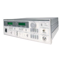
ILX Lightwave LDC-3900 User Manual (206 pages)
Modular Laser Diode Controller
Brand:
ILX Lightwave
| Category:
Controller
| Size: 1 MB
Table of Contents
Table of Contents
3
List of Figures
9
Safety and Warranty Information
13
Safety Information and the Manual
13
General Safety Considerations
13
Safety Symbols
14
Safety Marking Symbols
14
Warranty
15
Limitations
15
Returning an Instrument
15
Claims for Shipping Damage
15
Comments, Suggestions, and Problems
16
In the United States
16
In Europe
16
In Japan
16
In China
16
Chapter 1 Introduction and Specifications
19
Product Overview
19
Available Options and Accessories
20
Table 1.1 LDC-3900 Options and Accessories
20
Line Voltage Selection
21
Specifications
21
Table 1.2 GPIB Specifications
21
Table 1.4 General Specifications
21
Chapter 2 Operation
23
Installation
23
AC Power Considerations
23
Tilt-Foot Adjustment
24
Rack Mounting
24
Power-Up Sequence
24
Table 2.1 LDC-3900 Default Settings
26
LDC-3900 Front Panel
27
Front Panel
27
Figure 2.2 GPIB Section
28
Figure 2.1 LDC-3900 Front Panel
28
General Functions
28
Figure 2.3 Laser Enable Switch
29
Figure 2.4 Adjust Section
29
Figure 2.5 Output Section
29
Figure 2.9 TEC Parameters
31
Figure 2.8 TEC Display
31
Figure 2.7 TEC Mode
31
Conditions Which will Automatically Shut off a TEC Output
32
Figure 2.10 TEC Display
32
Figure 2.11 Laser Mode
33
Figure 2.12 Laser Display
33
Figure 2.13 Laser Parameters
33
Figure 2.14 Laser Display
33
Figure 2.15 Modulation
34
GPIB Section
34
Adjust Section
35
Automatic Set Point Adjustment
35
Output Section
36
TEC Mode Section
36
Figure 2.16 LDC-3900 TEC Mode Section
37
TEC Display Switch Section
37
TEC Mode Indicators
37
TEC Mode Select
37
Figure 2.17 LDC-3900 TEC Display Switch Section
38
TEC Display Indicators and Switches
38
TEC Display Set
38
Figure 2.18 LDC-3900 TEC Parameter Section
39
TEC Parameter Section
39
TEC Parameter Select
39
Lim Ite
40
Lim Thi
40
TEC Parameter Set
40
Const
41
Gain
41
Figure 2.19 LDC-3900 TEC Error Section
42
Table 2.2 TEC Error Indicators
42
TEC Channel Indicators
42
TEC Error Indicators
42
Figure 2.20 LDC-3900 Laser Mode Section
43
Laser Mode Section
43
Figure 2.21 LDC-3900 Laser Display Switch Section
44
Laser Display Switch Section
44
Laser Mode Indicators
44
Laser Mode Select
44
Laser Display Indicators and Switches
45
Laser Display Set
45
Figure 2.22 LDC-3900 Laser Parameter Section
46
Laser Parameter Section
46
Laser Parameter Select
46
Cal Pd
47
Laser Parameter Set
47
Lim I
47
Lim P
47
Figure 2.23 LDC-3900 Laser Error Section
48
Laser Channel Indicators
48
Laser Error Indicators
48
Figure 2.24 LDC-3900 MODULATION Section
49
Modulation Section
49
Table 2.3 Laser Error Indicators
49
Laser Functions
32
Automatic Laser Shutoff Conditions
34
Figure 2.6 Parameter Section
30
TEC Functions
30
Save and Recall Parameter Functions
49
Rear Panel Controls and Connections
51
Figure 2.25 LDC-3900 Rear Panel
51
GPIB Connector
51
Earth Ground Connector
52
Modulation from Front Connector
52
General Operating Procedures
52
Warm-Up and Environmental Considerations
52
TEC Mode Operation
52
Laser Mode Operation
53
Simultaneous TEC and Laser Mode Operation
54
TEC Booster Mode Operation
54
Chapter 3 Remote Operation
55
Preparation for Bus Control
56
ANSI/IEEE-488.2 Definitions
56
Syntax Diagrams
56
White Space
57
Figure 3.1 White Space Syntactic Diagram
58
Figure 3.2 <PROGRAM MESSAGE TERMINATOR> Syntax Diagram
59
Figure 3.5 <Compound Command Program Header> Syntax Diagram
61
Figure 3.6 <Compound Query Program Header> Syntax Diagram
61
Arbitrary Block Program Data
62
Figure 3.7 <ARBITRARY BLOCK PROGRAM DATA> Syntax Diagram
62
Program Data Separators
62
PROGRAM DATA> (Parameters)
62
Default Parameters
63
Figure 3.4 <PROGRAM HEADER SEPARATOR> Syntax Diagram
60
Program Header Separator
60
Power-On Conditions
58
Nrf Value
58
Program Message Terminator
58
Figure 3.3 <PROGRAM MESSAGE UNIT SEPARATOR> Syntax Diagram
59
Program Message Unit Separator
59
Compound Command Program Header
60
Table 3.1 State of the LDC-3900 after *RST
63
Figure 3.8 <PROGRAM DATA SEPARATOR> Syntax Diagram
63
Getting Started with GPIB
64
Overview of the LDC-3900 Syntax
64
Using Commands with Parameters
65
Common Commands and Queries
66
Cal
66
Cls
67
Ese
67
Enable Register
68
Figure 3.9 Standard Event Status Register/Standard Event Status
68
Figure 3.10 Service Request Enable Register
76
Sre
77
Stb
77
Tst
78
Wai
78
Ese
69
Esr
69
Idn
69
Opc
70
Psc
71
Psc
72
Pud
72
Pud
73
Rcl
73
Rst
74
Sav
75
Sre
75
Advanced Programming
79
Path Specification
79
Timing Considerations
80
Error Messages
81
Status Reporting
82
Event and Condition Registers
82
Figure 3.11 LDC-3900 Status Reporting Schematic Diagram
83
Command Timing and Completion
84
Operation Complete Definition
84
Figure 3.12 an LDC-3900 LASER Module Output off Register
86
Output off Registers
86
Figure 3.13 an LDC-3900 TEC Module Output off Register
87
Input Buffer and Output Data
88
Table 3.2 LDC-3900 Default Settings for Output off Registers
88
Chapter 4 Command Reference
91
Command Set Overview
91
Compound Command Structure
92
Substitute Parameter Names
92
Table 4.1 Substitute Parameter Names
92
Table 4.2 LDC-3900 Device-Dependent Command Summary
93
Command Paths
101
Common Commands
93
LDC-3900 Device-Dependent Commands
93
Figure 4.1 Command Path Tree Structure
102
LDC-3900 Device-Command Reference
103
Error Messages
192
Table 5.1 Error Code Classifications
193
Table 5.2 LDC-3900 Modular Laser Diode Controller Error
194
Chapter 5 Error Messages
197
Appendix A Steinhart-Hart Equation
197
The Steinhart-Hart Equation
197
Table A.1 Comparison of Curve Fitting Equations
198
Figure A.1 Thermistor Resistance Vs. Temperature
199
Appendix B AD590 and LM335 Sensor Calibration
201
Introduction
201
AD590 Sensor
201
Figure B.1 AD590 Nonlinearity
202
LM335 Sensor
203
One Point Calibration Method
204
Two Point Calibration Method
204
Advertisement
ILX Lightwave LDC-3900 User Manual (4 pages)
Modular Laser Diode Controller
Brand:
ILX Lightwave
| Category:
Controller
| Size: 0 MB
Table of Contents
Introduction and Specifications
2
Product Overview
2
Available Options and Accessories
3
Specifications
4
Line Voltage Selection
4
GPIB Specifications
4
General Specifications
4
Advertisement
Related Products
ILX Lightwave LDC-3916
ILX Lightwave LDC-3916370 Series
ILX Lightwave LDC-3916372
ILX Lightwave LDC-3916374
ILX Lightwave LDC-3916376
ILX Lightwave LDC-3916371
ILX Lightwave LDC-3908
ILX Lightwave LDC-3916372 R01
ILX Lightwave LDC-3926
ILX Lightwave LDC-3700C Series
ILX Lightwave Categories
Controller
Portable Generator
Temperature Controller
Measuring Instruments
Control Unit
More ILX Lightwave Manuals
Login
Sign In
OR
Sign in with Facebook
Sign in with Google
Upload manual
Upload from disk
Upload from URL