Table of Contents
Advertisement
Quick Links
Advertisement
Table of Contents

Related Manuals for ILX Lightwave LDC-3700C Series


Summary of Contents for ILX Lightwave LDC-3700C Series
- Page 1 User’s Guide Laser Diode Controller LDC-3700C Series ILX Lightwave Corporation · 31950 Frontage Road · Bozeman, MT, U.S.A. 59715 · U.S. & Canada: 1-800-459-9459 · International Inquiries: 406-556-2481 · Fax 406-586-9405 · ilx.custhelp.com www.ilxlightwave.com 70041001 April 2009...
-
Page 3: Table Of Contents
General LDC-3700C Specifications ........9 Available Options and Accessories ......11 04_09 LDC-3700C Series... - Page 4 Functions and Features ......... . 37 LDC-3700C Series...
- Page 5 Query Response Timing ........61 04_09 LDC-3700C Series...
- Page 6 Error Messages ..........157 LDC-3700C Series...
- Page 7 Figure 2.3 Rear Panel TEC Connector ..... . . 19 Figure 2.4 LDC-3700C Series Rear Panel ....39 Figure 2.5 Rear Panel TEC Connector .
- Page 8 L I S T O F F I G U R E S LDC-3700C Series...
-
Page 9: Ist Of
Table 5.5 Error Messages ....... . 157 04_09 LDC-3700C Series... - Page 10 L I S T O F TA B L E S viii LDC-3700C Series...
-
Page 11: Safety Information And The Manual
• Prolonged storage under adverse conditions • Failure to perform intended measurements or functions If necessary, return the instrument to ILX Lightwave, or authorized local ILX Lightwave distributor, for service or repair to ensure that safety features are maintained (see the contact information on page xiii). -
Page 12: Safety Marking Symbols
S A F E T Y S Y M B O L S All instruments returned to ILX Lightwave are required to have a Return Authorization Number assigned by an official representative of ILX Lightwave Corporation. See Returning an Instrument on page xi for more information. -
Page 13: Limitations
Returning an Instrument If an instrument is to be shipped to ILX Lightwave for repair or service, be sure to: Obtain a Return Authorization number (RA) from ILX Customer Service. -
Page 14: Claims For Shipping Damage
Shipping damage is not covered by this warranty. Secure the packing box with fiber reinforced strapping tape or metal bands. Send the instrument, transportation pre-paid, to ILX Lightwave. Clearly write the return authorization number on the outside of the box and on the shipping paperwork. ILX Lightwave recommends you insure the shipment. -
Page 15: Comments, Suggestions, And Problems
WA R R A N T Y Comments, Suggestions, and Problems To ensure that you get the most out of your ILX Lightwave product, we ask that you direct any product operation or service related questions or comments to ILX Lightwave Customer Support. - Page 16 WA R R A N T Y in a container with at least 3 inches (7.5cm) of compressible packaging material on all sides. We look forward to serving you even better in the future! LDC-3700C Series...
-
Page 17: Introduction And Specifications
C H A P T E R NTRODUCTION AND PECIFICATIONS This chapter is an introduction to the LDC-3700C Series Laser Diode Controllers and contains unpacking information, instructions on how to install and apply power, maintenance information, specifications, and listings of the LDC-3700C options and accessories. -
Page 18: Installing The Ldc-3700C
AC Line Power Requirements You can operate the LDC-3700C Series Controllers from a single phase power source delivering nominal line voltages of 100, 120, 220, 230-240 VAC (all values RMS) from 50 to 60 Hz. The line power voltage can vary ±10%. Maximum power consumption is 360 VA (Volt-Amps). -
Page 19: Gpib Connector
20 meters (65 feet) total, or 2 meters (6.5 feet) per device. The GPIB Address The talk and listen addresses on the LDC-3700C Series Laser Diode Controller are identical. This GPIB address is read locally by pressing the GPIB LOCAL switch with the address displayed on the "TEC"... -
Page 20: Figure 1.1 Ldc 3700C Series Controller Front View
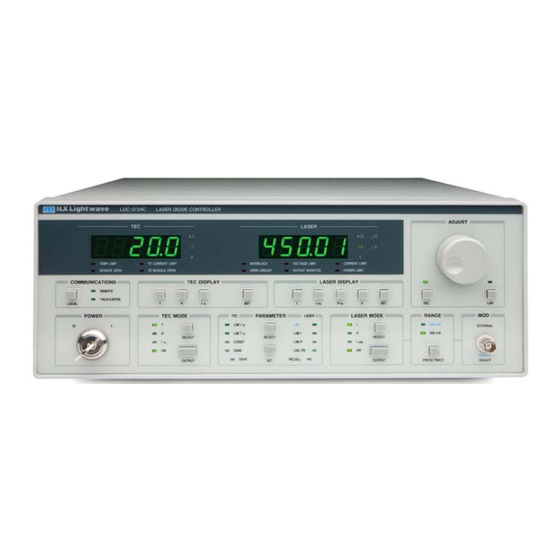
Figure 1.1 LDC 3700C Series Controller Front View Figure 1.2 LDC-3700C Rear Panel Potentially lethal voltages exist within the LDC-3700C Series Laser Diode Controller. To avoid electric shock, do not perform any maintenance on the instrument. Qualified service personnel are required to wear protective eyeglasses and anti-static wrist bands while working on the LDC-3700C Series Laser Diode Controller circuit boards. -
Page 21: How To Obtain Repair Services
Installing the LDC-3700C How to Obtain Repair Services You may have to return your controller to the ILX Lightwave facility at some time for repair or service whether it is under warranty or not. There is a charge for repairs after the warranty period has expired. See Returning an Instrument on page xi for shipping information and Customer Service contact information. -
Page 22: Laser Current Source Specifications
PD Reverse Bias 0 - 5 V, adjustable 0 - 5 V, adjustable 0 - 5 V, adjustable PD Current Range 5 to 5000 µA 5 to 5000 µA 5 to 10000 µA Output Stability 0.02% 0.02% 0.02% LDC-3700C Series... - Page 23 50% modulation depth at mid-scale output. Higher bandwidth is possible with smaller modulation signal. Responsivity value is user-defined and is used to calculate the optical power. Four wire voltage measurement at the load. Voltage measurement accuracy while driving calibration load. Accuracy is dependent upon load and cable used. 04_09 LDC-3700C Series ...
-
Page 24: Temperature Controller Specifications
I(25°C) = 298.2 µA, I = 1 µA/K LM335 Voltage Output V(25°C) = 2.73 V, V = 10 mV/K R(25°C) = 109.73 RTD (Pt ) Resistance User Calibration Thermistor: Steinhart-Hart, 3 constants IC Sensors, RTD = Two-point LDC-3700C Series... -
Page 25: General Ldc-3700C Specifications
Photodiode Monitor and Current Source Connector 9-pin, D-sub, female External Modulation Connector Temperature Controller 15-pin, D-sub, female Trigger Output Chassis Ground 4 mm banana jack GPIB INTERFACE Meets ANSI/IEEE Std 488.1 - 1987 Meets ANSI/IEEE Std 488.2 - 1987 USB INTERFACE 04_09 LDC-3700C Series ... - Page 26 0°C to +40°C operating -40°C to +70°C storage Humidity < 90% relative humidity, non-condensing Laser Safety Features Key switch, interlock and output delay (meets CDRH US21 1040.10) LASER Display Type 5-digit, green LED TEC Display Type 5-digit, green LED LDC-3700C Series...
-
Page 27: Available Options And Accessories
I N T R O D U C T I O N A N D S P E C I F I C A T I O N S C H A P T E R General LDC-3700C Specifications Available Options and Accessories Options and accessories available for the LDC-3700C Series Controllers include the following: Table 1.1 Options and Accessories DESCRIPTION... - Page 28 I N T R O D U C T I O N A N D S P E C I F I C A T I O N S C H A P T E R General LDC-3700C Specifications LDC-3700C Series...
-
Page 29: Applying Power To Your Ld Controller
C H A P T E R PERATIONS This chapter introduces you to the operation of the LDC-3700C Series Controllers. It offers instructions for connecting your laser to the current source and temperature controller and describes powering up the instrument. This chapter... -
Page 30: The Power On State
(depending on the setting of the SENSOR • LASER I Set Point = 0 mA SELECT switch) • LASER P Set Point = 0 mW • LASER IPD Set Point = 0 µA • CAL PD = 0 mA/mW LDC-3700C Series... -
Page 31: Connecting To The Laser Controller
When disconnecting devices, it is only necessary to turn the LASER Output off. ILX also recommends that the connections to the LDC-3700C Series Laser Diode Controller output be made using twisted wire pairs with an earth-grounded shield (see Figure 2.1 on page 16). -
Page 32: Figure 2.1 Laser Diode Connection Configurations
OUTPUT Bias Common Laser Cathode Photodiode Anode P. D. L. D. Earth Ground 3700B Series Laser Diode Controller OUTPUT Common Laser Anode Bias Photodiode Cathode P. D. L. D. Earth Ground Figure 2.1 Laser Diode Connection Configurations LDC-3700C Series... -
Page 33: Connecting The Laser Current Source
Usually, this photodiode is internally connected to either the laser anode or cathode. The photodiode and laser connections to the LDC-3700C Series Laser Diode Controller are electrically isolated from ground and each other. So, if a 4-pin... -
Page 34: Setting The Pd Bias
ADJUST fully counter-clockwise Grounding Considerations The LASER outputs of the LDC-3700C Series Laser Diode Controller are isolated from chassis ground allowing either output terminal to be grounded at the user's option. Figure 2.1 on page 16 shows the proper earth-ground shielding for laser diode/photodiode connections. -
Page 35: Connecting To The Te Controller
They are intended for use with an external TE Booster. TEC Grounding Considerations The TEC outputs of the LDC-3700C Series are isolated from chassis ground, allowing either output terminal to be grounded. If a terminal is grounded, make sure to connect it only to the Earth ground. -
Page 36: Operating From The Front Panel
C H A P T E R Operating from the Front Panel Operating from the Front Panel This section describes fundamentals of operation for your LDC-3700C Series Controller Laser Current Source in two operating modes, Constant Current (I), and Constant Power (P). -
Page 37: Set The Range
Before adjusting the set point check the LASER display for proper display mode; the display mode determines which set point is being adjusted. Adjust the set point to 150 mA. Pressing the SET switch in the LASER 04_09 LDC-3700C Series ... -
Page 38: Set Current Source Limit
The current limit setting is independent of the voltage drop of the device connected to the LASER output, and therefore, no dummy load is required for precise adjustment of the current limit. Furthermore, since the current limit LDC-3700C Series... -
Page 39: Set Compliance Voltage Limit
When the LASER output is off, an internal short is placed across the LASER output and the Output Shorted indicator illuminates. The default condition for the current source output is off when the instrument is first powered up. LASER MODE SELECT OUTPUT 04_09 LDC-3700C Series ... -
Page 40: Automatic Shutoff Conditions For Laser Output
CAL PD is selected and the display indicates the responsivity parameter in A/mW (not annunciated). Rotate the adjust knob in the ADJUST section while holding the (PARAMETER) SET push button to enter a LDC-3700C Series... - Page 41 (LASER DISPLAY) SET switch and ADJUST knob are released, the SET mode will time out in three seconds. The new set point will be stored in non-volatile memory. If the original display mode 04_09 LDC-3700C Series ...
- Page 42 LASER MODE section, enable the output of the laser current source by depressing the OUTPUT push button once. The accompanying led labeled ON will illuminate indicating that the laser output is on and current is being driven to LDC-3700C Series...
- Page 43 C H A P T E R Operating from the Front Panel the laser. The Controller's laser source will drive the laser to the Constant Power set point and maintain closed loop control with the PD current measurement. LASER MODE SELECT OUTPUT 04_09 LDC-3700C Series ...
-
Page 44: Laser Error Indicators
C H A P T E R Operating from the Front Panel LASER Error Indicators The LDC-3700C Series Laser Diode Current Source Controllers indicate general LASER operational error conditions. Each error condition results in a controller action as shown in the following table. -
Page 45: Operating The Te Controller From The Front Panel
Operating the TE Controller from the Front Panel Operating the TE Controller from the Front Panel This section describes how to operate your LDC-3700C Series Controller Temperature Controller in Constant Temperature Mode, T. There are several modes in which you can operate the temperature controller, Constant... -
Page 46: Temperature Controller Sensor Selection
10 k thermistor is to use the 10 µA range for temperatures between -30°C and +30°C , and the 100 µA range for temperatures between +10 to +70°C For a more complete description of thermistor selection see our Application Note #2 titled, "Selecting and Using Thermistors for Temperature Control". LDC-3700C Series... -
Page 47: Setting Temperature Sensor Constants
LIM I LIM T LIM I SELECT CONST LIM P CAL PD GAIN SAVE RECALL The ILX Lightwave Application Note #17 contains information on sensor calibration constants for AD590 and LM335 sensors. Since these devices are 04_09 LDC-3700C Series ... -
Page 48: Setting Te Control Loop Gain
°C. When the R switch is pressed, the display will show the measured thermistor resistance in k, the measured LM335 voltage in mV (not annunciated), or the measured AD590 current in µA (not annunciated), LDC-3700C Series... -
Page 49: Setting Temperature Controller Limits
To set the controller temperature limit to 40°C, press the (PARAMETER) SELECT switch until the LIM T indicator illuminates. Press and hold in the SET switch and turn the ADJUST knob until the TEC display indicates 40°C. When the SET 04_09 LDC-3700C Series ... -
Page 50: Adjusting The Temperature Set Point
Adjusting the Temperature Set Point Now, you are ready to adjust the set point operating temperature of the controller to 35°C. The LDC-3700C Series Temperature Controller will monitor actual temperature and adjust TE current to maintain the thermal load at the set point temperature. -
Page 51: Operating The Controller In Resistance (Sensor) Mode, R
• Sensor Open (while Output is enabled) • TEC Module Open (while Output is enabled) • SENSOR SELECT Switch Moved (while Output is enabled) • Sensor Shorted (while Output is enabled) • TEC mode changed (while output is enabled) 04_09 LDC-3700C Series ... -
Page 52: Tec Error Indicators
C H A P T E R Operating the TE Controller from the Front Panel TEC Error Indicators The LDC-3700C Series Laser Diode TEC Controllers indicate general TEC operational error conditions. Each error condition results in a controller action as shown in the following table. -
Page 53: Functions And Features
TEC display. If you desire to change the RECALL bin, press the SET switch and rotate the ADJUST knob until the desired bin number is displayed. Releasing the SET switch completes the RECALL operation. The 04_09 LDC-3700C Series ... -
Page 54: Using The Laser Compliance Voltage Adjustment
The LDI command does not. With this command, some trigger pulses may be missed if the program step time is less than the 20 ms minimum. A one shot trigger pulse will occur on power up of the instrument due to the states of the processor I/O. LDC-3700C Series... -
Page 55: Modulating The Controller Laser Current Source
Figure 2.4 LDC-3700C Series Rear Panel Modulating the Controller Laser Current Source The LDC-3700C Series Laser Diode Controller allows a modulated signal to be superimposed on the LASER injection current. For example, assume you are using an LED for your experiment where you need operate the led in constant current at P = 1 mW, and a modulated injection current from 3 to 30 kHz. - Page 56 LIM I SELECT CONST LIM P CAL PD GAIN SAVE RECALL When the laser current limit is reached, the CURRENT LIMIT error indicator flashes. The current limit setting is independent of the voltage drop of the device LDC-3700C Series...
-
Page 57: Boosting The Te Controller
Boosting the TE Controller For users who need more than 16 Watts of TE Controller power, a booster current source may be required and the LDC-3700C Series Temperature Controller may be used as the control element. This section describes the use of the LDC-3700C's Temperature Controller as a remote temperature controller. - Page 58 TTL-level indicators of the TEC voltage and limit conditions, respectively. They are useful for external sensing of these conditions in addition to the normal status reporting of the LDC-3700C Series instrument. Pin 13 is used as an external shutoff switch. Although it is labeled as "Temp.
-
Page 59: Remote Operation
Laser Diode Controller remotely through the USB or GPIB interface. USB Operations To begin using the USB port on the LDC-3700C Series Laser Diode Controller, please install the Virtual Com Port Driver which is available on the companion CD or from our website (www.ilxlightwave.com). A standard USB "A/B" cable is necessary to connect the instrument to a PC and is included in the shipping kit. -
Page 60: Basic Gpib Concepts
If there is more than one controller, only one can be the Controller In Charge (CIC). Control can be passed from one controller to another. In a multiple controller system, there can be one "System Controller'\" capable of asserting control (becoming CIC). LDC-3700C Series... -
Page 61: Gpib Cable Connections
• REN (remote enable) is set by the controller to place addressed devices into remote or local (front panel) control mode. • SRQ (service request) can be set by any device in the system to request service from the controller. 04_09 LDC-3700C Series ... -
Page 62: Reading The Gpib Address
SET switch. The new GPIB address will then be stored in non-volatile memory. The allowable address range is 0-30 for primary GPIB addressing. Extended GPIB addressing is not implemented on the LDC-3700C Series Laser Diode Controller at this time. GPIB REMOTE... -
Page 63: Changing Operation From Local To Remote
LOCAL switch returns the instrument to LOCAL control mode unless the Local Lockout state has been activated by the host computer. Local Lockout disables all LDC-3700C Series Laser Diode Controller front panel switches until this condition is changed by the host computer. When the instrument is put in Local Lockout Mode by the host computer, the REMOTE indicator will flash at a 1 Hz rate to indicate that the front panel is completely disabled by Local Lockout. -
Page 64: Command Syntax
OK. A query has no space between the mnemonic and the question mark. For example: Okay Not Okay TIMER? TIMER ? Note that too many consecutive white spaces can overflow the 256-byte data I/O buffer. LDC-3700C Series... -
Page 65: Terminators
"floating point", and "scientific notation". For example the number "twenty" may be represented by any of the following ASCII strings: Integer Floating point 20.0 +20.0 Scientific notation 2.0E+1 +2.0E+1 2.0e+1 +2.0e+1 For more information on these definitions, refer to the IEEE-488.2 standard. 04_09 LDC-3700C Series ... -
Page 66: Command Tree Structure
RESET If multiple parameters are expected, they should be separated with commas. For example, to set the Steinhart-Hart constants on the LDC-3700C Series Laser Diode Controller (C1, C2, and C3) the following command could be sent: TEC:CONST 1.111, 2.004, 0.456 If not all of the parameters need to be changed the other parameters may be omitted. -
Page 67: Syntax Summary
A single white space must separate a command from its parameters or data. White space is normally the space character (space bar). Other control characters are also interpreted as white space. Do not use white space before the question mark in a query command. 04_09 LDC-3700C Series ... -
Page 68: Table 3.2 Invalid Syntax Command Strings
Missing colon, MODE? expected. TEC:MODE T Missing semicolon, DEC command generates an TEC:MODE:R DEC error. Space not allowed before question mark, DIS LAS:DIS ? command expected. Space missing between LDI command and the Las:LDI33;dis? parameter value, 33. LDC-3700C Series... -
Page 69: Ieee488.2 Common Commands
*ESR? *IDN? *OPC *OPC? *PSC *PSC? *PUD *PUD? *RCL *RST *SAV *SRE? *SRE *STB? *TST? *WAI See the Command Reference on page 69 for descriptions of all the commands, including common commands, supported by the LDC-3700C. 04_09 LDC-3700C Series ... -
Page 70: Ldc-3700C Commonly Used Commands
Used to enter temperature sensor constants, C1, C2, and C3 TEC:CONST NONE Used to read back the temperature sensor constant values. TEC:CONST? Used to set the TEC control loop gain parameter. TEC:GAIN Used to set the TEC constant current source limit value. TEC:LIM:ITE LDC-3700C Series... -
Page 71: Status Reporting
LDC-3700C Series Laser Diode Controller. Events differ from conditions in that events signal an occurrence once, and are not reset until the Event Register is queried or the LDC-3700C Series Laser Diode Controller is powered off. Conditions reflect the current state of the device, and therefore may change many times during operation. -
Page 72: Operation Complete Definition
This allows the use of the operation complete features of the LDC-3700C Series Laser Diode Controller, without the need for program looping or polling which can tie up the communications. Operation Complete on the LDC-3700C Series Laser Diode Controller is defined as: •... -
Page 73: Figure 3.5 Status Reporting Scheme
R E M O T E O P E R A T I O N C H A P T E R Command Syntax Figure 3.5 Status Reporting Scheme 04_09 LDC-3700C Series ... -
Page 74: Output Off Registers
11- enabled 3- enabled 11- N/A 4- N/A 12- N/A 4- N/A 12- N/A 5- N/A 13- N/A 5- enabled 13- N/A 6- N/A 14- N/A 6- enabled 14- N/A 7- N/A 15- N/A 7- enabled 15- N/A LDC-3700C Series... -
Page 75: Figure 3.6 Laser Output Off Register
& Logical & & & & & & & & & 7 6 5 4 3 2 1 0 TEC Output Off Enable Register Turn Output Off TEC:ENABle:OUTOFF <nrf> TEC:ENABle:OUTOFF? Figure 3.7 TEC Output Off Register 04_09 LDC-3700C Series ... - Page 76 3- High Temperature Limit 11- N/A 4- N/A 12- N/A 5- Booster Changed (while output on) Eve. 13- N/A 6- Sensor Open (while output on) Cond. 14- N/A 7- TEC Module Open (output on) Cond. 15- N/A LDC-3700C Series...
-
Page 77: Command Timing
Query responses are evaluated at the time the query request is parsed, and not at the time the response message is sent. In most cases this does not create a problem since the time between parsing a query and sending its response is small. 04_09 LDC-3700C Series ... - Page 78 R E M O T E O P E R A T I O N C H A P T E R Command Syntax LDC-3700C Series...
-
Page 79: Command Reference
This chapter is a guide to all of the device-dependent commands for the LDC-3700C Series Laser Diode Controller. This chapter is divided into two parts. The first part contains an overview of the remote commands used by the LDC-3700C Series Laser Diode Controller. The second part contains all of the LDC-3700C Series Laser Diode Controller commands in alphabetical order. -
Page 80: Remote Command Reference Summary
Remote Command Reference Summary Remote Command Reference Summary This section contains all of the commands for the LDC-3700C Series Laser Diode Controller, listed in alphabetical order. Sub-sections for each path are presented, listing the commands which are legal for that path. See Figure 3.3 on page 51 for command path tree structure. - Page 81 Used to set the constant optical power set point, if PD LAS:MDI responsivity is 0. NONE Used to return the monitor PD current measured value. LAS:MDI? Used to set the constant optical power set point. LAS:MDP 04_09 LDC-3700C Series ...
- Page 82 *SRE generation of the user-selectable service requests. Determines the current contents of the Service Request Enable *SRE? Register. Reads the Status Byte. *STB? Factory use only. TEC:CAL:CONST? Used to enter the TEC current source calibration mode. TEC:CAL:ITE LDC-3700C Series...
- Page 83 Returns the mode, ITE (TEC current), R (sensor) or T TEC:MODE? (temperature). NONE Sets the mode to constant TEC current mode. TEC:MODE:ITE NONE Sets the mode to constant thermistor resistance/linear sensor TEC:MODE:R reference mode. NONE Sets the TEC mode to constant temperature mode. TEC:MODE:T 04_09 LDC-3700C Series ...
- Page 84 TIME? NONE Returns the elapsed time since the timer was last reset. TIMER? Initiates an internal self-test and returns a response when *TST? complete. Prevents executing any further commands until the No- *WAI Operation-Pending flag is true. LDC-3700C Series...
-
Page 85: Command Reference
Command Reference The following pages contain a reference for the device-dependent commands of the LDC-3700C Series Laser Diode Controller. This reference contains useful information for both local and remote operation of the LDC-3700C. In some references, parentheses are used to signify the labeled area for a particular switch or LED indicator on the front panel. - Page 86 Bit 5 of the status byte register is set if any enabled conditions are true. Setting bit 0 allows you to generate service requests from overlapped commands as previous oper-ations complete. This may be useful for ensuring that an operation is complete before starting a measurement. LDC-3700C Series...
- Page 87 2- Query Error 6- User Request 3- Device Dependent Error 7- Power On Notes Bit 5 of the status byte register is set if any enabled conditions are true. Response is the sum of the enabled bits. 04_09 LDC-3700C Series ...
- Page 88 5- Command Error 2- Query Error 6- User Request 3- Device Dependent Error 7- Power On Notes Response is the sum of the enabled bits. This command allows you to determine which type of error has occurred. LDC-3700C Series...
- Page 89 Parameters An <nrf value>, in microamps/milliwatt. The range is 0 to 1000. Notes If the parameter is set to 0, the LDC-3700C Series Laser Diode Controller will operate in a constant I mode, when Constant P mode is selected. The parameter should be set to 0 for I operation modes.
- Page 90 The LASer:CALMD? query returns the value of the laser's photodiode feedback responsivity (CAL PD parameter) setting. Notes If this value is 0, the LDC-3700C Series Laser Diode Controller will be set to operate in constant I mode, and the I set point value will be in effect.
- Page 91 Diode Controller is ready for a value to be entered during the calibration cycle of the LASer:CAL:LDI mode. Notes After this query is issued and a response of 1 is received, the LDC-3700C Series Laser Diode Controller will be ready for the user to enter a current value via the LASer:LDI command (see Chapter 6).
- Page 92 Diode Controller is ready for a value to be entered during the calibration cycle of the LASer:CAL:MDI mode. Notes After this query is issued and a response of 1 is received, the LDC-3700C Series Laser Diode Controller be ready for the user to enter a photodiode current value via the LASer:MDI command (see Chapter 6).
- Page 93 *CLS command is issued. Examples "LAS:COND?" -response: 513, means that the LASER limit current and out of tolerance LASER conditions currently exist. "Radix Hex; Laser:Cond?" -response: #H108, means that the LASER Output shorted and Power limit conditions currently exist. 04_09 LDC-3700C Series ...
- Page 94 LASER display, and all of the LASER section's indicator LEDs will be turned off. Examples "las:dis 1" -action: turns the LASER display on and enables the LASER indicator LEDs. "Laser:dis Off" -action: turns the LASER display and disables the LASER indicator LEDs. LDC-3700C Series...
- Page 95 The LASer:DISplay:LDV command sets the laser display to show the laser forward voltage measurement. Parameters None. Notes The actual LASER V display is turned off automatically when another LASER DISPLAY selection is enabled. Examples "LAS:DIS:LDV" -action: enables the LASER display for forward voltage values in Volts. 04_09 LDC-3700C Series ...
- Page 96 "LAS:DIS:MDI?" -response: 0, means that the (LASER DISPLAY) I switch is not currently active, laser photodiode monitor current is not displayed. "Las:dis:MDI?" -response: 1, means that the (LASER DISPLAY) I switch is currently active, monitor PD current may be displayed. LDC-3700C Series...
- Page 97 Each time the command is issued, the next LASER parameter will be selected, see Chapter 2 for more information. Examples "Laser:Display:Param" -action: selects a LASER parameter and displays its value. "LAS:DIS:PARAM" -action: selects a LASER parameter and displays a its value. 04_09 LDC-3700C Series ...
- Page 98 The set point display will not time out when REMOTE operation is used. (It will be continuously displayed.) Examples "LAS:DISPLAY:SET?" -response: 0, means the measured value is enabled for the LASER display. "Las:Dis:Set?" -response: 1, means the set point value is enabled for the LASER display. LDC-3700C Series...
- Page 99 Open circuit and LASER current limit conditions will be summarized in the status byte (bit 3). Laser:Enable:Cond #H0F9B" - action: enables the LASER status condition register so that any and all of the above conditions will be reported in the status byte register (bit 3). 04_09 LDC-3700C Series ...
- Page 100 LASER conditions will be reported (in summarized form) to the status byte (bit "Radix Hex; Laser:Enable:Cond?" -response: #H0F9B, means that all of the above conditions will be reported (in summarized form) to the status byte (bit 3). LDC-3700C Series...
- Page 101 Open circuit and Power limit events will be reported (in summarized form) to the status byte (bit 2). "Laser:Enable:Event #H0F9B" -action: enables the LASER status event register so all of the above events will be reported (in summarized form) to the status byte (bit 2). 04_09 LDC-3700C Series ...
- Page 102 Interlock changed LASER events will be reported (in summarized form) to the status byte register (bit 2). "Radix Hex; Las:Enab:Eve?" -response: #HF9B, means that all of the above events will be reported (in summarized form) to the status byte register (bit 2). LDC-3700C Series...
- Page 103 LASER current limit conditions will cause the LASER output to be turned off. "Las:Enab:Outoff #HE0B" -action: enables the LASER status outoff register so that any or all of the above conditions will cause the LASER output to be turned off. 04_09 LDC-3700C Series ...
- Page 104 "LAS:EVE?" -response: 513, means that the LASER output tolerance changed and current limit events have occurred since the last LASer:EVEnt? query. "Radix Hex; Laser:Event?" -response: #H88, means that the LASER Power limit and Open circuit events have occurred since the last LASer:EVEnt? query. LDC-3700C Series...
- Page 105 Set point is the same for both low and high bandwidth output modes. Examples "Las:LDI 400" -action: sets the laser output current to 400.00 mA. "LAS:ldi 1000" -action: sets the laser output current to 1000.0 mA. 04_09 LDC-3700C Series ...
- Page 106 The current limit is in effect in all modes of operation of the laser output with respect to the output range (low/high). Examples "LAS:LIM:I1 80" -action: the LASER current limit is set to 80 mA. ":Laser:Limit:I1 60" -action: the LASER current limit is set to 60 mA. LDC-3700C Series...
- Page 107 The current limit is valid for all modes of Laser operation for the respective output range. Examples "LAS:LIM:I2?" -response: 40, means the laser current limit is 40 mA. "Laser:LIM:I2?" -response: 150, means the laser current limit is 150 mA . 04_09 LDC-3700C Series ...
- Page 108 The current limit is in effect in all modes of operation of the laser output and the respective output range Examples "LAS:LIM:I4 800" -action: the LASER current limit is set to 800 mA. ":Laser:Limit:I4 2600" -action: the LASER current limit is set to 2600 mA. LDC-3700C Series...
- Page 109 The current limit is valid for all modes of Laser operation with respect to the current output range. Examples "LAS:LIM:I5?" -response: 400, means the laser current limit is 400 mA (LDC-3724C only). "Laser:LIM:I5?" -response: 50, means the laser current limit is 50 mA. 04_09 LDC-3700C Series ...
- Page 110 Turn the ADJUST knob until the desired value is displayed, and then release the SET switch. Examples "LAS:LIM:V 5.0" -action: the LASER compliance voltage limit is set to 5.0 volts. ":Laser:Limit:V 4.60" -action: the LASER compliance voltage limit is set to 4.6 volts. LDC-3700C Series...
- Page 111 "Las:Mode:MDP; Las:Calmd 0; Las:MDi?" -response: 100.0, means 100 A of Examples photodetector current. This feedback is controlling the laser current output. "LAS:MODE:IHBW; LAS:MDI?" -response: 20.0, means 20 A of photodetector current, but photodiode monitor current is not controlling the laser output current. 04_09 LDC-3700C Series ...
- Page 112 CALMD > 0. "Las:Mode?" -response: MDI, means that constant P (power) mode is in effect for the laser output, "Laser:MODE?" -response: IHBW, means that constant I (current, high bandwidth) mode is in effect for the laser output. LDC-3700C Series...
- Page 113 (if CALMD = 0) in A, or P In this mode, the displayed parameter will be either I CALMD > 0) in mW. Examples "LAS:MODE:MDP" -action: sets the laser output mode of operation to constant optical power mode. 04_09 LDC-3700C Series ...
- Page 114 "Las:OUT?" -response: 0, means that the output switch is disabled, devices may be safely disconnected or connected at the LASER output terminals. "LAS:OUT?" -response: 1, means that the LASER output switch is enabled, LASER output is present. LDC-3700C Series...
- Page 115 The Laser Drive Current output should be "off" when this command is issued. If the Laser Diode Current output is "on" when this command is issued, the LDC-3700C Series Laser Diode Controller will generate error #515, and the range will not be changed.
- Page 116 "Las:Mode:i; Las:ldi 20; Las:Step 100; Las:Inc; Las:set:ldi?" -action: sets the step to 1.0 mA (3724C), so the Las:set:ldi? query will return a value of 21.0 mA. "LAS:STEP 1000" -action: sets the step size to 1000; could mean 10.0 mA (3724C), 10.0 mW, or 100 A. LDC-3700C Series...
- Page 117 0.001 to 50.000 seconds. Notes The LDC-3700C Series Laser Diode Controller defaults to a tolerance of 10.0 mA for 5 seconds, unless changed by the LASer:TOLerance command. If the LDC-3700C Series Laser Diode Controller is operated in P mode, the current tolerance parameter is not used.
- Page 118 The LASer:TOLerance? query allows the programmer to determine how the LASER current tolerance is set. Notes The tolerance of the LDC-3700C Series Laser Diode Controller LASER current may be used to delay programming after an "LASer:OUTput 1" command is issued or the set point is changed.
- Page 119 In the enabled state, the enable registers are cleared during power ON. The power-on status clear flag (see PSC?) is set true, allowing service request interrupts after power- Examples Disable automatic power-on clearing of the enable registers. *PSC 0 *PSC 1 Enable automatic power-on clearing of the enable registers. 04_09 LDC-3700C Series ...
- Page 120 "SECURE <nrf>" command and is usually entered by the factory. Notes The arbitrary block program data is exactly 25 bytes long. *PUD? OMMON EVICE EPENDENT RONT ANEL Action Requests the factory-stored identification string. LDC-3700C Series...
- Page 121 Decimal, binary, octal, and hexadecimal are allowed. Notes DEC is the default type. The LDC-3700C Series Laser Diode Controller defaults to this radix at power-up. The RADix command is used to select the desired radix. Once it is changed, the new radix will remain in effect until the power is shut off or a new RADix command is issued.
- Page 122 It is normally not necessary to save the current setup for next power-ON. The current setup is automatically stored for recall at next power-ON unless you use *PSC not to do Example *SAV 2—Save the current setup configuration as #2. LDC-3700C Series...
- Page 123 (8 + 64 + 128 = 200) TEC:CAL:CONST OMMON EVICE EPENDENT RONT ANEL The TEC:CAL:CONST? query returns a stored calibration value. It is intended for factory use only. 04_09 LDC-3700C Series ...
- Page 124 ITE limit to 4.0 amps, and drive the output to 1.0 amps. This procedure is outlined in Chapter 6. The TEC:CAL:ITE? query (or bit 11 of the TEC status condition register) may be used to determine if the LDC-3700C Series Laser Diode Controller is ready for the user to enter a value. Examples "Tec:CAL:ITE"...
- Page 125 TEC:CAL:SENsor mode. Notes This query can be used to poll the LDC-3700C Series Laser Diode Controller after the TEC:CAL:SEN command to determine if it is waiting for a value. If the response is 1, the LDC-3700C Series Laser Diode Controller is ready to receive a calibration value via the TEC:R command (Chapter 6).
- Page 126 TEC:CAL:V mode. Notes This query can be used to poll the LDC-3700C Series Laser Diode Controller after the TEC:CAL:V command to determine if it is waiting for a value. If the response is 1, the LDC-3700C Series Laser Diode Controller is ready to receive a calibration value via the TEC:V command (Chapter 6).
- Page 127 "TEC:Const ,4.5,0.3" -action: sets C2 to 4.500, C3 to 0.300, and C1 is unchanged. "Tec:CONST 1.4,2.015" -action: sets C1 to 1.400, C2 to 2.015 for two-point calibration of AD590 or LM335 sensors (C3 is unchanged, but not used). 04_09 LDC-3700C Series ...
- Page 128 Returns the actual (6-character) string from the output buffer to the TEC display. If the display is disabled, it returns " .". Examples "TEC:DIS?" -response: "- 99.9", means "- 99.9" is on the TEC display. "Tec:DISp?" -response: " 0.6", means " 0.6" is on the TEC display. LDC-3700C Series...
- Page 129 Each time the command is issued, the next TEC parameter will be selected, see Section 2.9. Examples ":Tec:Display:Param" -action: selects a TEC parameter and displays its value. "TEC:DIS:PARAM" -action: selects a TEC parameter and displays its value. 04_09 LDC-3700C Series ...
- Page 130 Examples "Tec:Dis:Set" -action: enables the TEC display for the set point of the selected mode: ITE, R or T. "TEC:Dis:Set" -action: enables the TEC display for the set point of the selected mode: ITE, R or T. LDC-3700C Series...
- Page 131 Examples "TEC:Dis:T?" -response: 0, means that the TEC DIS T switch is not enabled, TEC load temperature is not displayed. "Tec:dis:T?" -response: 1, means that the TEC DIS T switch is enabled, temperature may be displayed. 04_09 LDC-3700C Series ...
- Page 132 Output Out of Tolerance and TE Current Limit conditions will be reported in the status byte register. "Tec:Enable:Cond #H0DFB" -action: enables the TEC status condition register so that any and all of the above conditions will be reported in the status byte register. LDC-3700C Series...
- Page 133 "TEC:ENAB:COND?" -response: 129, means that the TE Module Open and TE Current Limit conditions may be reported in the status byte register. "Radix Hex; TEC:Enable:Cond?" -response: #H0EFB, means that any and all of the above conditions will be reported in the status byte register. 04_09 LDC-3700C Series ...
- Page 134 (bit 1). "Tec:Enable:EVEnt #H0EFB" -action: enables the TEC status event register so that any and all of the above events will be reported (in summarized form) to the status byte register (bit 1). LDC-3700C Series...
- Page 135 Out of Tolerance TEC events will be reported (in summarized form) to the status byte register (bit 0). "Radix Hex; TEC:Enab:Eve?" -response: #H0EFB, means that all of the above events will be reported (in summarized form) to the status byte register (bit 0). 04_09 LDC-3700C Series ...
- Page 136 The High Temperature Limit Condition, Sensor Open (While Output On) Condition, and Sensor Type Change (While Output On) Event bits will not be in effect and will not cause the TEC output to be shut off, if the LDC-3700C Series Laser Diode Controller is in ITE mode.
- Page 137 "Radix Hex; TEC:Enab:Outoff?" -response: #H17FB, means that all of the above conditions will cause the TEC output to be turned off. "Radix Bin; TEC:Enab:Outoff?" -response: #B1001, means that the High Temperature Limit and TE Current Limit conditions will cause the TEC output to be turned off. 04_09 LDC-3700C Series ...
- Page 138 1, a value of 1 will be stored. If the user enters a value which is not legal, the LDC-3700C Series Laser Diode Controller will round that value to the nearest legal value, if possible.
- Page 139 TEC DISPLAY area of the front panel, and visually reading the value on the TEC display. Examples "TEC:ITE?" -response: 2.43, means the measured TEC output current is 2.430 Amps. "Tec:Ite?" -response: -3.27, means the measured TEC output current is -3.270 Amps. 04_09 LDC-3700C Series ...
- Page 140 The default setting of the TEC outoff enable register forces the TEC output to be shut off if the high temperature limit is reached. (See the TEC:ENABle:OUTOFF command.) Examples "TEC:LIM:THI 100" -action: sets the TEC load temperature limit to 100.0C. "Tec:Lim:thi 30.3" -action: sets the TEC load temperature limit to 30.3C. LDC-3700C Series...
- Page 141 Changing modes causes the output to be forced off, and the new mode's set point value will be dis-played. Examples "TEC:MODE:ITE" -action: sets the TEC controller for constant TEC current operation. "Tec:Mode:Ite" -action: sets the TEC controller for constant TEC current operation. 04_09 LDC-3700C Series ...
- Page 142 After the output is turned on, it may be useful to wait until the output is stable (within tolerance) before performing further operations, but it is not necessary. Examples "TEC:OUTPUT 1" -action: turns the TEC output on. "Tec:Out 0" -action: turns the TEC output off. "Tec:Out OFF" -action: turns the TEC output off. LDC-3700C Series...
- Page 143 10.543 mV, depending on the SENSOR SELECT switch position. "Tec:R?" -response: 0.728, means the measured TEC thermistor resistance is 728 ohms, or the measured AD590 current is 0.728 A, or the measured LM335 voltage is 0.728 mV, depending on the SENSOR SELECT switch position. 04_09 LDC-3700C Series ...
- Page 144 "TEC:SET:R?" -response: 3.4, means the R set point is 3.400 k, or 3.40 A, or 3.4 mV, Examples depending on the SENSOR SELECT switch position. "Tec:Set:R?" -response: 4.0, means the R set point is 4.000 k, or 4.00 A, or 4.0 mV, depending on the SENSOR SELECT switch position. LDC-3700C Series...
- Page 145 This measurement is updated approximately once every 600 msec. The response value has 6 digits of precision. Examples "TEC:T?" -response: 10.4231, means the measured TEC load temperature is 10.4231C. "Tec:Mode:R; Tec:T?" -response: -3.0778, means the measured TEC load temperature is -3.07780C. 04_09 LDC-3700C Series ...
- Page 146 10C for a period of 5 seconds. Notes The LDC-3700C Series Laser Diode Controller defaults to a tolerance of 0.2C for 5 seconds, unless changed by the TEC:TOLerance command. In R mode the temperature and time parameters are both in effect, as in T mode.
- Page 147 TEC output circuit. Examples "Tec:V?" -response: "0.2", means the LDC-3700C Series Laser Diode Controller has a TEC voltage of 0.2 volts. "TEC:v?" -response: "1.2", means the LDC-3700C Series Laser Diode Controller has a TEC voltage of 1.2 volts.
- Page 148 Notes An altered terminator will be in the form <CR><NL><^END>. This termination will be sent with all output until the "TERM 0" command is sent or the LDC-3700C Series Controller is powered off. Examples "Term?"...
- Page 149 TIMER? is issued its response will be the same as if a TIME? query's response. Examples "Timer?" -response: 00:02:00.31, means the LDC-3700C Series Laser Diode Controller has been on for 2 minutes and 0.31 seconds since the last TIMER? query was issued.
- Page 150 C O M M A N D R E F E R E N C E C H A P T E R Command Reference LDC-3700C Series...
-
Page 151: Calibration Overview
ALIBRATION AND ROUBLESHOOTING This chapter describes calibration of your LDC-3700C Series Laser Diode Controller. Descriptions of the required test instruments, calibration conditions, and the detailed procedures for calibration of the instrument's Temperature Controller and the Laser Diode Current Source are included. A troubleshooting guide is also offered for some of the more common failure symptoms. -
Page 152: Recommended Equipment
0-50C. Finally, the LDC-3700C Series Laser Diode Controller should be allowed to warm up for at least 1 hour before calibration. Recommended Equipment Recommended test equipment for calibrating the LDC-3700C Series Laser Diode Controller is listed in Table 5.1. -
Page 153: Figure 5.1 Ipd Calibration Circuit
C H A P T E R Calibration Overview calibration circuit with the required components listed in Table 5.2 on page 138. Also, the devices required for other calibration loads are listed in Table 5.2. Figure 5.1 I Calibration Circuit 04_09 LDC-3700C Series ... -
Page 154: Table 5.2 Required Calibration Components
49 resistor, 1% 1/4W 100 resistor, 1%, 1/4W 1.0 M resistor, 1% 1/4W 20 , 1%, 1 W LDC-3714C 5 , 1%, 10 W LDC-3724C, LDC-3744C TIL 111 opto isolator Battery 9 V Battery Connector 9-pin D-sub, Male LDC-3700C Series... -
Page 155: Local Calibration Of The Ldc-3700C Temperature Controller
TEC display indicates the same resistance you recorded for the metal film resistor. Release the (PARAMETER) SET switch to store the new value into non-volatile memory. After the (PARAMETER) SET switch is released, the LDC-3700C Series Laser Diode Controller will return to its former state (before calibration). -
Page 156: Ad590 Sensor Calibration
TEC display indicates the same current as shown on the multimeter. Release the (PARAMETER) SET switch to store the new value into non-volatile memory. After the SET switch is released, the LDC-3700C Series Laser Diode Controller will return to its former state (before calibration). -
Page 157: Ite Current Calibration
TE current output to internally set limits of 2 amp. When each of these values is reached and is stable, the user enters the actual value of the current, as measured by an external DMM. The LDC-3700C Series Laser Diode Controller then automatically calibrates the TEC current source and limits. -
Page 158: Local Calibration Of The Laser Current Source
Local Calibration of the Laser Current Source There are three calibration adjustments required for the LASER current source of the LDC-3700C Series Laser Diode Controller. They are: calibration of the constant current source for both bandwidths and ranges, calibration of the laser... - Page 159 (PARAMETER) SET switch is released, the Controller will calculate the calibration constants, store them to nonvolatile memory. In low bandwidth calibration mode, the LDC-3700C Series Laser Diode Controller will also perform current limit calibrations for I(Constant Current) and P(Constant Power) modes, indicated by the CURRENT LIMIT LED flashing.
-
Page 160: Ipd Current Calibration
After the value on the LASER display is stable (has not changed by more than one digit for several seconds) the LDC-3700C Series Laser Diode Controller is ready for the actual value to be entered. Press and hold in the (PARAMETER) SET switch and turn the ADJUST knob until the... - Page 161 LASER display indicates the actual current as measured by the ammeter or as calculated. Release the (PARAMETER) SET switch to accept the second calibration point. After the (PARAMETER) SET switch is released, the LDC-3700C Series Laser Diode Controller will calculate the calibration constants and store them to nonvolatile memory.
-
Page 162: Laser Forward Voltage Measurement Calibration
(1/4) of the original value. It will then expect the second calibration voltage point. Input the second actual (measured) LASER forward voltage. Once the second actual voltage value is entered, the Controller stores the new calibration constants. LDC-3700C Series... -
Page 163: Remote Calibration Of The Ldc-3700C Controller
*OPC? query should not be issued until after the expected calibration value is entered, or the system will "hang". This happens because the LDC-3700C Series Laser Diode Controller will wait indefinitely for an input, yet not allow any input until the calibration is finished. -
Page 164: Ad590 Sensor Calibration
TEC:CAL:SEN? query is sent, the response from the Controller is "1". Once the TEC:R value is sent, the Controller will return to its former state (before calibration). The *OPC? query may be used (after the TEC:R value is sent) to determine when the calibration is completed. LDC-3700C Series... -
Page 165: Ite Current Calibration
TE current output to internally set limits of ±2.000 amps. When each of these values is reached and is stable, the user enters the actual value of the current, as measured by an external DMM. The LDC-3700C Series Laser Diode Controller then automatically calibrates the TEC current source and limits. -
Page 166: Tec Voltage Calibration
The controller will drive the output current to a value of about 0.12 Amps, so that the TEC voltage will be about +6.00 volts. Repeat step 4. After the value for the positive polarity of the TEC voltage is entered, the Controller will automatically store the new calibration values for TEC voltage measurement. LDC-3700C Series... -
Page 167: Current Source Calibration
Current Source Calibration There are three calibration adjustments required for the LASER current source of the LDC-3700C Series Laser Diode Controller. They are calibration of the constant current source for both bandwidths and ranges, calibration of the laser voltage measurement, and calibration of the constant light power (I ) feedback circuits. - Page 168 Once the second actual I value is entered via the LAS:LDI command, the new calibration constants will be calculated and stored into non-volatile memory. In low bandwidth calibration mode, the LDC-3700C Series Laser Diode Controller will also perform current limit calibrations for I and P modes as indicated by the CURRENT LIMIT LED flashing.
-
Page 169: Ipd Current Calibration
P modes. When these values are reached and are stable, the user enters the actual value of the current, as measured by an external DMM. The LDC-3700C Series Laser Diode Controller then automatically calibrates the LASER feedback circuits. -
Page 170: Laser Forward Voltage Measurement Calibration
Enter the measured voltage (in volts) via the LAS:LDV <nrf value> command. The measured value of the voltage should not be entered until the LDC-3700C Series Laser Diode Controller is ready to receive it. The Controller will be ready to receive the voltage value when, after a LAS:CAL:LDV? query is sent, the response from the Controller is "1". -
Page 171: Troubleshooting
C H A P T E R Troubleshooting Troubleshooting This section is a guide to troubleshooting the LDC-3700C Series Controllers. Some of the more common symptoms are listed here, and the appropriate troubleshooting actions are given. We recommend that the user start at the beginning of this guide. - Page 172 This indicates a voltage limit error. Check laser connections. A high impedance may cause this condition. Open circuit error E503 or Voltage Limit The LDC-3700C Series instruments have an error E505 prevents output from reaching adjustable laser compliance voltage. Check to see if desired value.
-
Page 173: Error Messages
<PROGRAM DATA> will not convert to valid type. E-203 Security violation, command is not available without clearance. E-205 <PROGRAM DATA> is not a Boolean value or word. E-207 <PROGRAM DATA> will not convert to an unsigned 16-bit value. 04_09 LDC-3700C Series ... - Page 174 LASER control error disabled output. E-512 Analog section status is all 1's or all 0's (power down). E-513 Serial EEPROM checksum error. E-515 Laser Output must be off to change ranges. E-516 Incorrect Configuration for Calibration Sequence to start. LDC-3700C Series...
- Page 175 Setting a measurement is only valid during the calibration phase for that measurement. User has tried to calibrate a measurement without first entering the required calibration mode. E-520 User cannot change the Laser Current set point while operating in a calibration mode for another measurement. 04_09 LDC-3700C Series ...
- Page 176 C A L I B R A T I O N A N D T R O U B L E S H O O T I N G C H A P T E R Troubleshooting LDC-3700C Series...
Need help?
Do you have a question about the LDC-3700C Series and is the answer not in the manual?
Questions and answers