
Related Manuals for ILX Lightwave LDC-3908


Summary of Contents for ILX Lightwave LDC-3908
- Page 1 (217) 352-9330 | Click HERE Find the Newport / ILX Lightwave LDC-3916376 at our website:...
- Page 2 User’s Guide Laser Diode Controller Mainframe LDC-3908 ILX Lightwave Corporation P. O. Box 6310 Bozeman, MT, U.S.A. 59771 · · · U.S. & Canada 1-800-459-9459 · International Inquiries: 406-586-1244 Fax 406-586-9405 · E-mail: support@ilxlightwave.com www.ilxlightwave.com 70031301 00_03/02 Artisan Technology Group - Quality Instrumentation ... Guaranteed | (888) 88-SOURCE | www.artisantg.com...
- Page 3 Artisan Technology Group - Quality Instrumentation ... Guaranteed | (888) 88-SOURCE | www.artisantg.com...
-
Page 4: Table Of Contents
Initial Inspection ........... . 2 Installing Your LDC-3908 Laser Diode Controller ......2 Grounding Requirements . - Page 5 Using the LDC-3908 Menu Structure ........10...
- Page 6 Chapter 4 Command Reference LDC-3908 Mainframe Command Reference ......29 Chapter 5 Functions and Features Saving and Recalling from the Front Panel .
- Page 7 Artisan Technology Group - Quality Instrumentation ... Guaranteed | (888) 88-SOURCE | www.artisantg.com...
-
Page 8: List Of Figures
Figure 1.1 LDC-3908 Controller Front View ......4 Figure 1.2 LDC-3908 Controller Rear View ......5 Figure 2.1 Display Controls Menu . - Page 9 Artisan Technology Group - Quality Instrumentation ... Guaranteed | (888) 88-SOURCE | www.artisantg.com...
-
Page 10: List Of Tables
List of Tables Table 1.1 LDC-3908 Fuse Replacement ......6 Table 1.2 General LDC-3908 Specifications ......6 Table 3.1 Substitute Parameter Names . - Page 11 Artisan Technology Group - Quality Instrumentation ... Guaranteed | (888) 88-SOURCE | www.artisantg.com...
-
Page 12: Safety And Warranty Information
• Prolonged storage under adverse conditions • Failure to perform intended measurements or functions If necessary, return the instrument to ILX Lightwave, or authorized local ILX Lightwave distributor, for service or repair to ensure that safety features are maintained (see the contact information on page xii). -
Page 13: Safety Symbols
Technical specifications including electrical ratings and weight are included within the manual. See the Table of Contents to locate the specifications and other product information. The following classifications are standard across all ILX Lightwave products: • Indoor use only • Ordinary Protection: This product is NOT protected against the harmful ingress of moisture. -
Page 14: Warranty
Returning an Instrument If an instrument is to be shipped to ILX Lightwave for repair or service, be sure to: Obtain a Return Authorization number (RA) from ILX Customer Service. Attach a tag to the instrument identifying the owner and indicating the required service or repair. -
Page 15: Comments, Suggestions, And Problems
W A R R A N T Y Comments, Suggestions, and Problems To ensure that you get the most out of your ILX Lightwave product, we ask that you direct any product operation or service related questions or comments to ILX Lightwave Customer Support. -
Page 16: Introduction And Specifications
Product Overview The LDC-3908 Laser Diode Controller is an instrument that holds up to 8 modules for controlling laser diode current and temperature. The current source modules provide high stability output with fully redundant current limits and multiple laser protection features. The temperature controller modules are compatible with most temperature sensors and TE modules to deliver precise laser temperature control over a wide range of temperatures. -
Page 17: Initial Inspection
I N T R O D U C T I O N A N D S P E C I F I C A T I O N S C H A P T E R Initial Inspection Initial Inspection When you receive your LDC-3908 Controller, verify that the following items were shipped with the instrument: • LDC-3908 Laser Diode Controller • LDC-3908 Mainframe Instruction Manual (optional) •... -
Page 18: Gpib Connector
The talk and listen addresses on the LDC-3908 Laser Diode Controller are identical. The controller comes from the factory configured with the GPIB address set to 1. You can change the LDC-3908's GPIB address locally (via the front panel). A procedure for changing the address can be found in Changing the GPIB Address on page 19. -
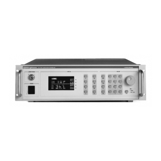
Page 19: Figure 1.1 Ldc-3908 Controller Front View
Menu Soft Keys Keys Keys Key Switch F1, F2, F3, F4 Adjust Knob Vacuum Fluorescent Numeric Keypad Power Switch Display Figure 1.1 LDC-3908 Controller Front View LDC-3908 Artisan Technology Group - Quality Instrumentation ... Guaranteed | (888) 88-SOURCE | www.artisantg.com... -
Page 20: Maintenance
High voltages are present on and around the Controller’s printed circuit boards. Fuse Replacement The LDC-3908 Controller has a line power fuse located on the rear panel inside the power input module, to the right of the power cord connector. Before replacing the fuses, turn power off and disconnect the power cord. -
Page 21: Table 1.1 Ldc-3908 Fuse Replacement
5 Amp, 3AG, 250V Slow Blo Disconnect power when replacing fuses. Make certain you install the correct fuse for your line voltage. If you install the incorrect fuse, damage to the LDC-3908 and possible personal injury may occur. Table 1.2 General LDC-3908 Specifications... -
Page 22: Chapter 2 Operations
C H A P T E R PERATIONS This chapter introduces you to the operation of the LDC-3908 eight-channel laser diode controller. It offers instructions for connecting your laser to the current source and temperature controller modules and describes powering up the instrument. The chapter also provides a description of the front panel controls, including both display and adjust controls. -
Page 23: Hard Keys
O P E R A T I O N S C H A P T E R LDC-3908 Front Panel Controls Hard Keys The menu structure is initiated using one of the primary Menu Control keys. These keys provide direct access to the Main and Channel menus as well as movement within the screens used most often for instrument control. -
Page 24: Adjust Knob
Applying Power to the Laser Diode Controller To turn on the LDC-3908, push the button in the Power section of the front panel to change the setting from zero (0) to one (1). This action will initiate the Power On Sequence. If the LDC-3908 does not appear to turn on, verify that it is connected to line power. -
Page 25: Using The Ldc-3908 Menu Structure
Status Screen. Power down the instrument and check to see if the modules are correctly seated and fastened to the mainframe. If you continue to experience power up problems, power down the instrument and contact an ILX Lightwave Customer Service Representative. -
Page 26: System Configuration
Figure 2.6 System Configuration Menu Communications Configuration If you intend to operate your LDC-3908 LD Controller remotely via GPIB (General Purpose Interface Bus) or through a serial RS-232 link, selecting Comm from the System Config. menu accesses the Config. Comm menu. Here you can view and change the GPIB address and the RS-232 BAUD rate. -
Page 27: Display Configuration
O P E R A T I O N S C H A P T E R Using the LDC-3908 Menu Structure Pressing the Up Arrow returns you to the Sys. Config. menu. Chapter 3 in both the Mainframe and Module manuals provides complete information on remote control operation. -
Page 28: Calibration
The Calibration Menu allows you to calibrate from the front panel all Laser and TEC functions for each of the modules (8 max.) you have loaded in the LDC-3908 Mainframe. Remote calibration through the IEEE488.2 GPIB or serial RS-232 interface is provided as well. (See Chapter 3.) ILX... -
Page 29: All Channel Menu
Drive modules (model LDC-3916376). For example, suppose you have an LDC-3908 with eight LDC-3916372 modules, and you wish to operate eight lasers in low bandwidth mode at 75 mA with a limit of 80 mA and a Vlim of 3.1V at 25o LDC-3908 Artisan Technology Group - Quality Instrumentation ... -
Page 30: Setting All Las
O P E R A T I O N S C H A P T E R Using the LDC-3908 Menu Structure C with a temperature limit of 40o C and a gain of 30 in the 100 uA sensor range (for measuring temperatures between 10×... -
Page 31: All Tec
O P E R A T I O N S C H A P T E R Using the LDC-3908 Menu Structure 40oC. Next set the mode to T for constant temperature mode by scrolling down to the Mode field and setting it as described above. -
Page 32: Mainframe Errors
O P E R A T I O N S C H A P T E R Using the LDC-3908 Menu Structure measured temperature, if either of the outputs is active (LAS/TEC), and any errors respective to a channel. The up arrow soft key returns you to the Main menu. -
Page 33: Status
O P E R A T I O N S C H A P T E R Using the LDC-3908 Menu Structure text is highlighted, the output is on for that respective channel. Blanks indicate that there is no module present in that slot. -
Page 34: Operating In Remote Control
LDC-3908 Laser Diode Controller remotely through the GPIB and RS-232 interfaces. GPIB Configuration Before you can operate the LDC-3908 from a remote location with GPIB, you need to know its GPIB address. The following sections describe reading and changing the GPIB address of the LDC-3908. -
Page 35: Rs-232 Configuration
Comm port on your PC. The following sections describe reading and changing the baud rate of the LDC-3908. The LDC-3908's RS-232 is configured for 8-bit, no parity. This is not adjustable. Only the baud rate may be altered. -
Page 36: Gpib Versus Rs-232 Communication
LDC-3908 Laser Diode Controller Command Set GPIB Versus RS-232 Communication The LDC-3908 should not be run remotely via GPIB and RS-232 at the same time. When using the RS-232 interface, the remote GPIB command set is fully operable. Command syntax does not vary between GPIB and RS-232 usage. -
Page 37: Ieee 488.2 Common Commands
Controller, the following command may be sent: TEC:CONST 1.111, 2.004, 0.456 The LDC-3908 uses a terminator of <NL><^END> (new line EOI). For users whose GPIB driver defaults expect a carriage return in the terminator, <CR><NL><^END>, the TERM command may be used for convenience (See TERM command in Chapter 4). For more information, refer to your GPIB driver configuration manual. -
Page 38: Ldc-3908 Mainframe Specific Commands
Chapter 4, Command Reference. LDC-3908 Mainframe Specific Commands The LDC-3908's command set can be divided into three categories: 1) IEEE 488.2 common commands, 2) LDC-3908 mainframe commands, and 3) module-dependent commands. The IEEE 488.2 common commands and LDC-3908 mainframe commands are documented in this manual. -
Page 39: Operation Complete Definition
ERROR QUEUE Figure 3.1 LDC-3908 Status Reporting Schematic Diagram Note: The LDC-3908 does not define operation completeness in the same way as earlier model ILX instruments. Care must be taken when using the *OPC, *OPC?, and *WAI commands with the LAS:OUT ON command, due to the two-second turn-on delay. -
Page 40: Error Messages
GPIB Errors E 700 to E 799 Mainframe Errors E 900 to E 999 Mainframe-to-Module Communication Errors Table 3.3 LDC-3908 Mainframe Error Message Codes Error Code Explanation E-124 Command not recognized by mainframe. E-125 Common command not recognized by mainframe. - Page 41 O P E R A T I N G I N R E M O T E C O N T R O L C H A P T E R Error Messages Table 3.3 LDC-3908 Mainframe Error Message Codes Error Code Explanation E 711 Over-temperature Error found on internal sensor #2.
-
Page 42: Table 4.1 Ldc-3908 Mainframe Device-Dependent Commands
Laser Diode Controller. The chapter is divided into two parts. The first contains an overview of the remote commands used by the LDC-3908, as shown below in Table 4.1. The second part contains all of the LDC-3908 command descriptions, listed in alphabetical order. Figure 4.1 shows the format for the device command descriptions in this chapter. -
Page 43: Command Reference
C O M M A N D R E F E R E N C E C H A P T E R Table 4.1 LDC-3908 Mainframe Device-Dependent Commands NAME PARAMETERS FUNCTION TERM Adds a carriage return to the device terminator. -
Page 44: Ldc-3908 Mainframe Command Reference
This section presents the mainframe device-dependent commands for both local and remote operation of the LDC-3908 Laser Diode Controller, listed in alphabetical order. Also included in this section are the descriptions of the generic module commands, see Figure 3.1. Refer to the appropriate module instruction manual for details on each specific module. - Page 45 C O M M A N D R E F E R E N C E C H A P T E R LDC-3908 Mainframe Command Reference ALLCOND? RONT ANEL EMOTE The ALLCOND? query returns the status summary of enabled conditions from each channel of the LDC-3908 Laser Diode Controller.
- Page 46 RONT ANEL EMOTE The BEEP command controls the LDC-3908 Laser Diode Controller's beeper. The beeper can be used to signal error or warning conditions. Parameters An <nrf value>, 0 = OFF (totally disabled); 1 = ON, enabled for normal operation; and 2 = beep once.
- Page 47 BEEP? RONT ANEL EMOTE The BEEP? query returns the enable status of the LDC-3908 Laser Diode Controller's beeper. Parameters None. A response of 0 = OFF (totally disabled); 1 = ON, enabled for normal operation. Notes Disabling the BEEP will prevent the audible beeper signal from working during front panel operation.
- Page 48 “DELAY 500" -action: Further commands and queries are not executed until 0.5 second has elapsed from the time this command is executed. "Tec:T 22;Delay 2000;Tec:T?" -actions: The TEC is set to 22.0×C, then the LDC-3908 Laser Diode Controller waits for about 2.0 seconds before measuring and returning the temperature.
- Page 49 C O M M A N D R E F E R E N C E C H A P T E R LDC-3908 Mainframe Command Reference MENU RONT ANEL EMOTE The MENU command causes the front panel display to switch to the specified menu.
- Page 50 C O M M A N D R E F E R E N C E C H A P T E R LDC-3908 Mainframe Command Reference MODIDN? RONT ANEL EMOTE The MODIDN? query returns the module's model name and serial number.
- Page 51 Notes This command affects the Status screen only. The scrolling rate is not adjustable. When the auto-scrolling feature is enabled it is in effect until it is disabled or the LDC-3908 is powered off. Examples “Scr 1" -action: Enables the auto-scrolling feature of the Status screen.
- Page 52 3908 Laser Diode Controller out of IEEE488.2 specification, but this command may be used for convenience when using non-standard GPIB controllers. This termination will be sent with all output until the “TERM 0" command is sent or the LDC-3908 Laser Diode Controller is powered off. Examples “Term 1"...
- Page 53 Artisan Technology Group - Quality Instrumentation ... Guaranteed | (888) 88-SOURCE | www.artisantg.com...
-
Page 54: Functions And Features
To access the Save/Recall mode, select SAV/REC from the System Configuration menu. To save the existing settings of the LDC-3908 (all settings on all channels will be saved), select the bin for saving. Then, press the Save soft key. -
Page 55: Modulating The Controller Laser Current Sources
Modulating the Controller Laser Current Sources Modulating the Controller Laser Current Sources The LDC-3908 Laser Diode Controller allows a modulated signal to be superimposed on the Laser current of any or all current source modules. The Modulation connector (BNC) on the back panel is the input for the modulated signal. -
Page 56: Index
20 RS-232 21 front panel 4, 7 communications configuration menu 11 fuses 5 connector modulation 6 RS-232 2, 6 connectors GPIB 3 controller-specific commands 23 LDC-3908 Artisan Technology Group - Quality Instrumentation ... Guaranteed | (888) 88-SOURCE | www.artisantg.com... - Page 57 17 save and recall 13 weight 6 status 16 summary 17 system configuration 11 menus 10 modulation 40 mounting rack 3 operation complete definition 24 LDC-3908 Artisan Technology Group - Quality Instrumentation ... Guaranteed | (888) 88-SOURCE | www.artisantg.com...
Need help?
Do you have a question about the LDC-3908 and is the answer not in the manual?
Questions and answers