Sign In
Upload
Download
Table of Contents
Contents
Add to my manuals
Delete from my manuals
Share
URL of this page:
HTML Link:
Bookmark this page
Add
Manual will be automatically added to "My Manuals"
Print this page
×
Bookmark added
×
Added to my manuals
Manuals
Brands
Acer Manuals
Desktop
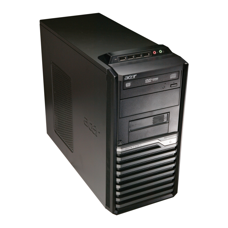
Veriton M670
Service manual
Acer Veriton M670 Service Manual
Acer personal computer user manual
Hide thumbs
1
2
3
4
5
Table Of Contents
6
7
8
9
10
11
12
13
14
15
16
17
18
19
20
21
22
23
24
25
26
27
28
29
30
31
32
33
34
35
36
37
38
39
40
41
42
43
44
45
46
47
48
49
50
51
52
53
54
55
56
57
58
59
60
61
62
63
64
65
66
67
page
of
67
Go
/
67
Contents
Table of Contents
Troubleshooting
Bookmarks
Table of Contents
Revision History
Table of Contents
Chapter 1 System Specifications
Features
S a V E & E X I T S E T U
Onboard Connectors
Power Supply
Main Board Placement
Block Diagram
Veritonm670G/M670 Front Panel
Veritonm670G/M670 Rear Panel
Veritons670G/S670 Front Panel
Veritons670G/S670Rear Panel
BIOS Hotkey List
Processor
Bios
Hardware Specifications and Configurations
Memory Combinations
System Memory
Audio Interface
Sata Interface
Environmental Requirements
Floppy Disk Drive Interface
Usb Port
Power Management
Power Management Function (ACPI Support Function)
Chapter 2 System Utilities
Entering Setup
Product Information
Standard CMOS Setup
Advanced BIOS Features
Advanced Setup
Advanced Chipset Setup
Integrated Peripherals
Power Management
P C H E a L T H S T a T U
Frequency/Voltage Control
Bios Security Features
Load Default Settings
Save and Exit Setup
Exit Without Saving
Chapter 3 Machine Disassembly and Replacement
General Information
Disassembly Procedure
Veritonm670G/M670/S670G/S670 Disassembly Procedure
Remove Cpu Fan Pipe
Remove Side Cover
Remove Cards
Remove Hdd Data Cables
Remove Hdd Power Cable
Remove Odd Data Cable
Remove Cables
Remove HDD
Remove Card Reader
Remove Fdd Cable
Remove Odd
Remove System Fan
Remove Mother Board
Remove Cpu Cooler
Remove Memory
Remove Cpu
Chapter 4 Troubleshooting
Chapter 5 Jumper and Connector Information
Chapter 6 FRU (Field Replaceable Unit) List
Exploded Diagram
Advertisement
Quick Links
1
Main Board Placement
2
Veritonm670G/M670 Front Panel
3
Processor
4
Memory Combinations
5
Chapter 5 Jumper and Connector Information
Download this manual
VeritonM670G/M670/
S670G/S670
Service Guide
Service guide files and updates are
available on the AIPG/CSD web; for
more information please refer to
http://csd.acer.com.tw
PRINTED IN TAIWAN
Table of
Contents
Previous
Page
Next
Page
1
2
3
4
5
Advertisement
Table of Contents
Need help?
Do you have a question about the Veriton M670 and is the answer not in the manual?
Ask a question
Questions and answers
Related Manuals for Acer Veriton M670
Desktop Acer Veriton 1000 User Manual
Veriton series (84 pages)
Desktop Acer Veriton 1000 User Manual
Veriton series (39 pages)
Desktop Acer VM670G-UQ9501C Specifications
(2 pages)
Desktop Acer Veriton Z280G Service Upgrades
Acer veriton z280g: supplementary guide (1 page)
Desktop Acer AcerPower APM6 Service Manual
Acer desktop computer service guide (164 pages)
Desktop Acer Aspire M5620 Service Manual
(91 pages)
Desktop Acer Veriton D461 Service Manual
Service guide (90 pages)
Desktop Acer Veriton M680G Service Manual
(88 pages)
Desktop Acer Veriton M6618G Service Manual
Acer veriton m6618g desktop service guide (136 pages)
Desktop Acer Veriton A430_31 User Manual
Generic user guide (38 pages)
Desktop Acer M678G Disassembly Manual
(18 pages)
Desktop Acer Veriton L4610G User Manual
Acer veriton l4610g: user guide (38 pages)
Desktop Acer Veriton M6610G Specifications
Veriton m6610g (2 pages)
Desktop Acer Veriton M6660G Recycling Manual
(20 pages)
Desktop Acer Aspire series User Manual
Aspire series (55 pages)
Desktop Acer Aspire M3420 Service Manual
Acer aspire m3420 desktop service guide (137 pages)
This manual is also suitable for:
Veriton m670g
Veriton s670
Veriton s670g
Veritonm670
Table of Contents
Save PDF
Print
Rename the bookmark
Delete bookmark?
Delete from my manuals?
Login
Sign In
OR
Sign in with Facebook
Sign in with Google
Upload manual
Upload from disk
Upload from URL


Need help?
Do you have a question about the Veriton M670 and is the answer not in the manual?
Questions and answers