Table of Contents
Advertisement
Quick Links
Use
CA1N4895en
08.03.2004
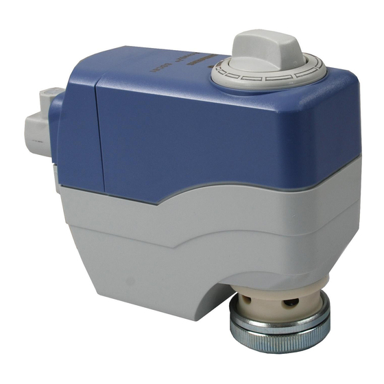
Electrical Actuators
for valves VVP45..., VXP45..., VMP45...
•
SSC31
operating voltage AC 230 V
•
SSC81
operating voltage AC 24 V
•
SSC61
operating voltage AC/DC 24 V
•
SSC61.5
same as SSC61, plus electrical fail-safe function
•
Nominal force 300 N
•
Automatic identification of valve stroke
•
Direct mounting with coupling nut, no tools required
•
Cable connection via screw terminals
•
Manual override, indication of position and direction of travel
•
Parallel connection of multiple actuators
•
Special UL-listed versions
For operation of Siemens valves of the VVP45..., VXP45... and VMP45... range
water-side control of hot water and cooling water in heating, ventilation and air
conditioning systems
.
In conjunction with the ASK30 mounting kit, the former Landis & Gyr valves VVG45...,
VXG45... and X3i... can also be operated.
3-position control signal
3-position control signal
DC 0...10 V control signal
Siemens Building Technologies
HVAC Products
4
895
SSC31
SSC81
SSC61...
for
Advertisement
Table of Contents

Related Manuals for Siemens SSC31


Summary of Contents for Siemens SSC31
- Page 1 Parallel connection of multiple actuators • Special UL-listed versions For operation of Siemens valves of the VVP45..., VXP45... and VMP45... range water-side control of hot water and cooling water in heating, ventilation and air conditioning systems In conjunction with the ASK30 mounting kit, the former Landis & Gyr valves VVG45..., VXG45...
-
Page 2: Equipment Combinations
• 3-position actuators Voltage at Y1: Actuator stem extends and valve opens • SSC31 / SSC81 Voltage at Y2: Actuator stem retracts and valve closes • No voltage at Y1 or Y2: Actuator maintains the current position •... -
Page 3: Auto Calibration
Manual adjustment with rotary knob • Reduced power consumption in the holding positions • Load-dependent switch-off in the event of overload and in stroke limit positions Accessories Mounting kit Type ASK30 Siemens Building Technologies Electrical Actuators CA1N4895en HVAC Products 08.03.2004... -
Page 4: Operation
SSC61.5 will first travel to position 0 and can then be driven manually to the required position. (Y, Y1) (Y2) Position indicator in Position indicator in position 1 = OPEN position 0 = CLOSED Siemens Building Technologies Electrical Actuators CA1N4895en HVAC Products 08.03.2004... -
Page 5: Maintenance
The technical data ( , leakage rates, noise levels, service life, etc.) relating to specific applications are valid only in conjunction with the Siemens valves listed in this Data Sheet under «Equipment combinations». The use of the SSC… actuators in conjunction with third-party valves invalidates any warranty offered by Siemens Building Technologies / HVAC Products. -
Page 6: Connection Terminals
Control signal OPEN System potential AC 24 V SSC61 Control signal DC 0...10 V SSC61.5 System potential AC 24 V (+ with DC 24 V) System neutral (- with DC 24 V) Siemens Building Technologies Electrical Actuators CA1N4895en HVAC Products 08.03.2004... -
Page 7: Connection Diagrams
Actuator System potential AC 24 V System neutral Q1, Q2 Controller contacts (G0) (Y1) (Y2) SSC61 Controller SP (+) SSC61.5 Actuator System potential AC 24 V System neutral (G0) SN (-) Siemens Building Technologies Electrical Actuators CA1N4895en HVAC Products 08.03.2004... - Page 8 Dimensions All dimensions in mm G¾ 115.1 132.5 2004 Siemens Building Technologies AG Subject to change Siemens Building Technologies Electrical Actuators CA1N4895en HVAC Products 08.03.2004...