Table of Contents
Advertisement
Quick Links
Download this manual
See also:
Owner's Manual
Advertisement
Table of Contents

Related Manuals for Viper 5902


Summary of Contents for Viper 5902
- Page 1 Responder HD Model 5902 Security and Remote Start Owner’s Guide © 2009 Directed Electronics, Vista, CA G5902V 2009-02...
-
Page 2: What You Get
Congratulations Congratulations on the purchase of your state-of-the-art remote start and security system. Due to the complexity of this system, it must be installed by an authorized dealer only. Installation of this product by anyone other than an authorized dealer voids the warranty. All dealers are provided with a preprinted dealer certificate to verify authorization. -
Page 3: Important Information
Important Information Please read the following information before using your new system. Government Regulations and Safety information Please read the material on pages XX before operating this system. Warning! The Government Regulations and Safety information in this manual is included by law and/or for your benefit. -
Page 4: Additional Information
• http://www.directed.com – For General information • http://www.viper.com/Support/ – For additional guide informa- tion or PDF version of this guide For any additional questions please contact your authorized Directed 1-800-753-0600... -
Page 5: Getting Started
Getting Started Your remote will first need to be charged before proceeding. If not already charged please do so now as you read on and familiarize yourself with the many feature your system offers. Charging the remote control Your remote control has an internal rechargeable battery. No other power source is required. -
Page 6: Replacement Remote Controls
• Plug in the charger, included in the box. • A standard mini USB cable connected to any standard USB port on any laptop or desktop computer can also be used. • The screen displays “CHARGE” while the battery level bars within the battery icon flash. -
Page 7: Table Of Contents
Contents Congratulations ....................3 What you get ....................3 Important Information ..................4 Government Regulations and Safety ............4 Your Warranty ..................4 Additional information ................4 Getting Started ....................6 Charging the remote control ...............6 Replacement remote controls ..............7 How to use your system ...................11 Introduction ....................11 Remote information at a glance ..............12 Low battery indication ................13 Battery life .....................13... -
Page 8: How To Use Your System
How to use your system Introduction © 2009 Directed Electronics. All rights reserved. -
Page 9: Remote Information At A Glance
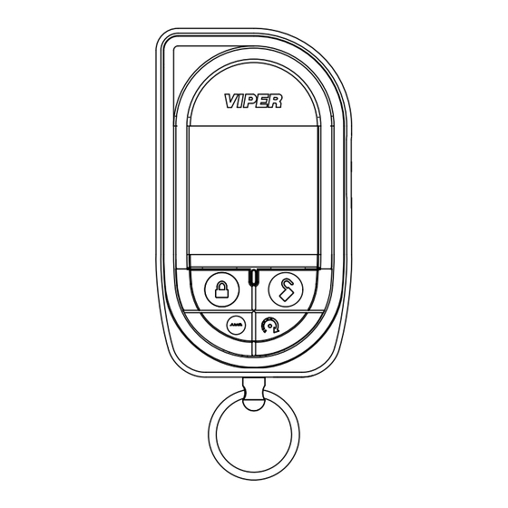
Remote information at a glance Internal Antenna Display Toggle Remote 1-800-274-0200 Switch Details RPN 7941V IC: 1513A-7941 FCC ID:EZSDEI7941 Lock Unlock Button Button Remote Reset Button Start Button Button Page Feature Description Internal Antenna * Used for transmitting and receiving information Display Full Color Organic Light Emitting Diode (OLED) Display Internal... -
Page 10: Low Battery Indication
Low battery indication When the batteries are low on the 2-way remote it emits two groups of beeps, the battery icon flashes and low battery is indicated, the alarm then emits an additional chirp upon disarming of the alarm to let you know it’s time to change the battery. -
Page 11: Battery Disposal
• Recommended: Turn on Battery Saver mode. When the remote control is not used for more than 72 hours, the remote control automatically will enter into a sleep state to conserve battery life. Pressing any of the command buttons will wake up the device for use. -
Page 12: Oled Color Display Status Icons
OLED color display status icons Clock Battery Level Paging Mode Timer Start/Smart Start Siren Status Remote Start Status Sensor Status Info Center Alarm Status Name Tag Note: Areas on display where icons have more than one state (look different to the ones shown above) are also covered below. Page Feature Description... - Page 13 Page Feature Description Alarm Status Alarm System is Unlocked and Alarm is disabled (continued) Note: Car 2 if applicable will have a 2 in the above icons Name Tag Description Info Center Displays information such as runtime, parking and count- down timer Sensor Status All Sensors are active and being monitored...
- Page 14 Page Feature Description Paging Mode Tone On & Battery Saver On (continued) Tone On, Vibe On & Page Off Screen Only On & Page On Screen Only On & Page Off Screen Only On & Battery Saver On © 2009 Directed Electronics. All rights reserved.
-
Page 15: Accessing Commands: Primary
Accessing commands: Primary Remote control commands are accessed by pressing one of the four command buttons located on the front of the remote. Primary commands are accessed when display is blank or status screen is active. Page Item Icon Name and Description Arm: Arm’s the alarm and locks the doors (if connected) Disarm: Disarm’s the alarm and locks the doors (if connected) AUX/Trunk: Activates Auxiliary channel to control popping of... -
Page 16: Accessing Commands: Secondary
Accessing commands: Secondary Secondary commands are accessed by use of the toggle switch lo- cated on the side of the remote by pressing up or down. Pressing up or down takes you through the additional 4 levels in reverse or forward continue holding respectively. - Page 17 Clock Name Tag Battery Level Paging Mode Timer Start/Smart Start Siren Status Remote Start Status Sensor Status Info Center Alarm Status Name Tag Page Item Name Description Silent Arm Arm’s the alarm and locks the doors (if connected) without chirps Silent Arm’s the alarm and locks the doors (if connected) Disarm...
- Page 18 Clock ame Tag Battery Level Timer Start/Smart Start Remote Start Status Alarm Status ame Tag Page Item Name Description Warn Bypasses warn away on all sensor trigger zones Away Shock Bypasses Shock sensor from triggering Sensor Optiona Bypasses optional sensors excluding shock sensor (if Sensors connected) Bypass All...
- Page 19 ame Tag Page Item Name Description Warn Bypasses warn away on all sensor trigger zones Away Shock Bypasses Shock sensor from triggering Sensor Optiona Bypasses optional sensors excluding shock sensor (if Sensors connected) Bypass All Bypasses all sensor trigger zones Page Item Name...
- Page 20 Page Item Name Description Car Select Used to select another vehicle with Responder HD system (if connected) Last Trigger Requests latest trigger information (if available) Aux 4 Not Applicable with this system Temp Requests vehicles temperature Request © 2009 Directed Electronics. All rights reserved.
-
Page 21: Configuring Your System
Configuring your system How to navigate through the menus Your HHU has many features which can be accessed and configured using the toggle switch found on the side of your remote. Directed has designed this system to be intuitive and easy to use by minimizing the steps involved to complete an action and by offering an on screen command guide once within a menu. - Page 22 Example: To set clock Press in hold toggle switch on side of remote until the “Set- tings” screen appears. Toggle switch down to the next screen (“Adjustments” screen). Press in toggle switch to access the “Adjustments” menu. press in Since “clock settings” is the first menu option, on the tog- gle switch again to access this menu (the other options in the Ad- justments menu can be access by toggling the switch up or down...
-
Page 23: Configuration Menus And Options
Configuration Menus and Options The following features are listed and defined in chronological order as they are found within your system. They are accessed and configured using the same process as shown in the previous example. Page Settings Button Auto Lock Alert Type Animations Button Beeps... - Page 24 Exit © 2009 Directed Electronics. All rights reserved.
-
Page 25: Feature Details
Feature Details © 2009 Directed Electronics. All rights reserved. -
Page 26: Glossary Of Terms
Glossary of Terms © 2009 Directed Electronics. All rights reserved. -
Page 27: Specifications
Specifications © 2009 Directed Electronics. All rights reserved. -
Page 28: Government Regulations
Government regulations This device complies with Part 15 of FCC rules. Operation is subject to the fol- lowing two conditions: (1) This device may not cause harmful interference, and (2) This device must accept any interference received, including interference that may cause undesirable operation. - Page 29 Control Center To satisfy FCC RF exposure compliance requirements, the device and its antenna must maintain a separation distance of 20 cm or more from the person’s body, except for the hand and wrists, to satisfy RF exposure compliance. This device complies with the Industry Canada Radio Standards Specification RSS 210.
-
Page 30: Warning! Safety First
Warning! Safety first Please read the safety warnings below before proceeding. Improper use of the product may be dangerous or illegal. Installation Due to the complexity of this system, installation of this product must only be performed by an authorized Directed dealer. If you have any questions, ask your retailer or contact Directed directly at 1-800-753-0600. - Page 31 Before remote starting a manual transmission vehicle, be sure to: • Leave the vehicle in neutral and be sure no one is standing in front or behind the vehicle. • Only remote start on a flat surface • Have the parking brake fully engaged WARNING! It is the responsibility of the owner to ensure the parking/emergen- cy brake properly functions.
-
Page 32: Interference
ING THE REMOTE START SYSTEM UNDER THESE CONDITIONS MAY RESULT IN PROPERTY DAMAGE OR PERSONAL INJURY. YOU MUST IMMEDIATELY CEASE THE USE OF THE UNIT AND SEEK THE ASSISTANCE OF AN AU- THORIZED Directed DEALER TO REPAIR OR DISCONNECT THE INSTALLED REMOTE START MODULE. -
Page 33: Limited Lifetime Consumer Warranty
Limited lifetime consumer warranty Directed Electronics. (“Directed”) promises to the original purchaser to repair or replace (at Directed’s election) with a comparable reconditioned model any Directed unit (hereafter the “unit”), excluding without limitation the siren, the remote transmitters, the associated sensors and accessories, which proves to be defective in workmanship or material under reasonable use during the lifetime of the vehicle provided the following conditions are met: the unit was purchased from an authorized Directed dealer, the unit was professionally... - Page 34 WITHOUT LIMITATION, LIABILITY FOR THEFT, DAMAGE AND/OR VANDALISM. THIS WARRANTY DOES NOT COVER LABOR COSTS FOR MAINTENANCE, REMOVAL OR REINSTALLATION OF THE UNIT OR ANY CONSEQUENTIAL DAMAGES OF ANY KIND. IN THE EVENT OF A CLAIM OR A DISPUTE INVOLVING DIRECTED OR ITS SUBSIDIARY, THE VENUE SHALL BE SAN DIEGO COUNTY IN THE STATE OF CALIFORNIA.
-
Page 35: Index
Index © 2009 Directed Electronics. All rights reserved. - Page 36 The company behind this system is Directed Electronics Since its inception, Directed Electronics has had one purpose, to provide consumers with the finest vehicle security and car stereo products and accessories available. The recipient of nearly 100 patents and Innovations Awards in the field of advanced electronic technology.
Need help?
Do you have a question about the 5902 and is the answer not in the manual?
Questions and answers