
Related Manuals for Indesit VIX644CE


Summary of Contents for Indesit VIX644CE
- Page 1 5413374 Issue 1 Feb. 2014 C00302243 ~ SM003818 INDESIT TOUCH CONTROL INDUCTION Model Comm. Covered Code VIX644CE 82475 Service Information Indesit Company UK Ltd © 2014 Reg. Office: Peterborough PE2 9JB Registered in London: 106725...
-
Page 2: Table Of Contents
Indesit Company SAFETY NOTES & GENERAL SERVICING ADVICE 1. This manual is NOT intended as a comprehensive repair/maintenance guide to the appliance. 2. It should ONLY be used by suitably qualified persons having technical competence applicable product knowledge and suitable tools and test equipment. -
Page 3: Serial Number / Industrial Code Explanation
Indesit Company SERIAL NUMBER / INDUSTRIAL CODE EXPLANATION Serial Number Example 3 10 02 0895 Four remaining digits = Build number that day 895 built Third two digits = Day of manufacture 2 of month Second two digits = Month of manufacture October... -
Page 4: Introduction
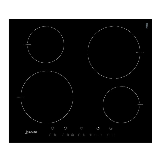
INTRODUCTION OF INDESIT TOUCH CONTROL INDUCTION HOB VIX644CE VIX644CE was introduced into the Indesit built-in range in June 2013. This model complies with the new Stand-By and safety regulations. It has 4 cooking zones with 4 individual controls. 2 x 1.5kW - Boost to 2kW, 2 x 1.2 kW - Boost to 1.6 kW. -
Page 5: Disposal
Indesit Company The induction system is the quickest existing way of cooking. Unlike traditional hotplates where the cooking zones heats up, with the induction system heat is generated directly inside pans which have ferromagentic bases. Appliance Total Loading 7.2 kW Mains Cable 6 x 1.5 mm... -
Page 6: Other Items Supplied
Indesit Company OTHER ITEMS SUPPLIED Service Manual UK English 6 of 33... -
Page 7: Safety Information
Indesit Company SAFETY INFORMATION Never • Never leave children unsupervised where a cooking appliance is installed as all surfaces will be hot during and even after its use. • Never allow anyone to sit or stand on any part of the appliance. - Page 8 Indesit Company ADVICE & RECOMMENDATIONS • This appliance was designed for non- • Certain fundamental rules must be followed professional, household use. when using electrical appliances. • Before using the appliance, read the instructions The following are of particular importance: in the owner’s manual carefully since it contains...
-
Page 9: General Safety
Indesit Company GENERAL SAFETY Make sure that the air inlet behind the fan grille is never obstructed. The built-in hob should, in fact, be provided with suitable ventilation for the cooling of the electronic components used in the appliance. We advise against the installation of an induction hob above an under-the-counter refrigerator (heat) or above a washing machine (vibrations). - Page 10 Indesit Company • Do not let children play with the appliance. • Do not place metal objects (knives, spoons, pan lids, etc.) on the hob as they may become hot. • The appliance is not intended to be operated by means of an external timer or separate remote control system.
-
Page 11: Installation & Fastening
Indesit Company INSTALLATION Taken from the Instructions for Installation and Use Before operating your new appliance please read the instruction booklet carefully. It contains important information concerning the safe operation, installation and maintenance of the appliance. Please keep the operating instructions for future reference. Pass them on to any new owners of the appliance. - Page 12 Indesit Company INSTALLATION continued.. Installation of the safety washer CABINET DIMENSIONS Min. 30/Max.50 SAFETY DISTANCES WITH FURNITURE Min 5mm Min 20mm 30mm Min 5mm 30mm Min 20mm Service Manual UK English 12 of 33...
- Page 13 Indesit Company INSTALLATION continued.. Fix the hob as follows: 1. Use short flat-bottomed screws to fix the 4 alignment springs in the holes provided at the central point of each side of the hob. 2. Place the hob in the cavity, make sure it is in a central position and push down on the whole perimeter until the hob is stuck to the supporting surface.
-
Page 14: Electrical Connection
Indesit Company ELECTRICAL CONNECTION The electrical connection for the hob and for any built -in oven must be carried out separately, both for safety purposes and to make extracting the oven easier. Single-Phase Connection The hob is equipped with a pre-connected electricity supply cable, which is designed for single-phase connection. -
Page 15: Description Of The Appliance
Indesit Company DESCRIPTION OF THE APPLIANCE The control panel described above is only a representative example, it may not exactly match the panel on this appliance. INCREASE (+) / REDUCE (-) POWER button - controls the power level on every individual cooking zone. -
Page 16: Start-Up & Use
Do not remove or replace the power supply cable for any reason. Its removal or replacement will void the warranty and the CE marking. INDESIT does not assume liability for accidents or damage arising from replacement/removal of the original power supply cable. Replacement can only be accepted when carried out by personnel authorised by INDESIT and using an original spare part. - Page 17 Indesit Company Initial Light Conditions When power is initially applied to the Cooktop, the touch control conducts a calibration process for the touch keys, which requires a low level of ambient light in the area of the touch keys. If during this calibration process excessive ambient lighting is detected the User Interface displays 'FL' (Infrared Ambient Light Error) and the control calibration process is suspended.
- Page 18 Indesit Company For selecting a new Power Limit: • With the (+) and (-) keys, the Power Limit is increased. The selectable powers are: 2800W, 3500W, 6000W or 7200W. When the power is 7200W, if the [+] or [-] key is touched the power changes to 2800W.
-
Page 19: Using The Timer
Indesit Company Using the Timer All the cooking zones can be programmed for a cooking time duration between 1 and 99 min. 1. Activate the timer by pressing the INCREASE or REDUCE TIME buttons. A beep sounds, the timer display shows a '00' and the cooking zone displays show a 't' blinking indicating that a cooking zone has to be selected. - Page 20 Indesit Company To use any of the controls (e.g. to stop cooking), you must switch off this function. Press the button for a few moments, the icon will stop illuminating and the lock function will be removed. All the keys on the cooking zone selection will be locked: if the cooktop is off;...
-
Page 21: Practical Advice On Using The Hobs
Indesit Company PRACTICAL ADVICE ON USING THE HOBS Use cookware made from materials which are compatible with the induction principle (ferromagnetic material). We especially recommend pans made from cast iron, coated steel or special stainless steel adapted for induction. Use a magnet to test the compatibility of the cookware. -
Page 22: The Safety Devices
Indesit Company THE SAFETY DEVICES Pan Sensor Each cooking zone is equipped with a pan sensor device. The hotplate only emits heat when a pan with suitable measurements for the cooking zone is placed on it. The 'U' sign on the display appears if after selecting the cooking zone the pan is not placed on a heater or in the case of: •... - Page 23 Indesit Company Buzzer This can indicate several irregularities: - • An object (a pan, cutlery, etc.) has been places on the control panel for more than 10 seconds. • Something has been spilt on the control panel. • A button has been pressed for too long.
-
Page 24: Practical Cooking Advice
Indesit Company PRACTICAL COOKING ADVICE ª Pressure cooking Frying Pressure cooker • Grilling Boiling • ¶ Crêpes Cooking on a high flame and browning (roasts, steaks, escalopes, fish fillets, fried eggs) ¶ § Fast thickening (liquid juices) Boiling water (pasta, rice, vegetables) Milk §... -
Page 25: Care & Cleaning
Indesit Company CARE & CLEANING Disconnect the hob from the electricity supply before carrying out any work on it. Cleaning the Appliance IMPORTANT: Do not use abrasive or corrosive detergents (for example, products in spray cans for cleaning barbecues and ovens), stain removers, anti-rust products, powder detergents or sponges with abrasive surfaces;... -
Page 26: Fault Codes
FAULT CODES Hob Status Fault Description Service Steps Codes Power increment not allowed Step 1 Power management activated, no fault. (hob in Eco Mode) Ensure correct pan size and that pan is suitable for induction cooking. Note that even though pan suitability is No pan or not suitable checked with a magnet, depending on pan base material (low ferromagnetic %) and pan base effective Step 1... - Page 27 FAULT CODES Hob Status Fault Description Service Steps Codes Step 2 If fault persists, service visit required. Step 3 Change user interface. Step 1 Ask the user to switch the power off and on (try to reset the system). Step 2 If fault persists, service visit required. Induction heater F / 1 temperature sensor...
- Page 28 FAULT CODES Hob Status Fault Description Service Steps Codes Step 4 If harness OK, change user interface. Step 5 If fault persists change Power board. Step 1 Ask the user to confirm correct connection to power supply, ensuring link is in place. Step 2 If external wiring and connection to appliance is correct service visit required.
- Page 29 FAULT CODES Hob Status Fault Description Service Steps Codes Step 2 If fault persists, service visit required. Step 3 Change user interface. User interface F / c Step 1 Advice the user not to put hot pans on control area. Wait until the system cools down. overtemperature Step 1 Ask the user to switch the power off and on (try to reset the system).
-
Page 30: Wiring Photo
Indesit Company WIRING DIAGRAM A full wiring diagram is currently not available for this product. Using these pictures wiring positions can be found. NOTE: - The Earth wire from the terminal block MUST be refitted to the metal chassis. Service Manual UK... -
Page 31: Dismantling Procedure
Indesit Company DISMANTLING INSTRUCTIONS Safety Notes 1. Before carrying out any work ensure that the appliance is disconnected from the mains supply. 2. Carry out insulation resistance, continuity and functional tests on the appliance after service. 3. Personal safety precautions must be taken to protect against accidents caused by sharp edges on metal, glass and plastic parts. - Page 32 Indesit Company C) Touch Control Printed Circuit Board Remove the hob top (A). Remove the 5 wire plug from the PCB. Disengage the plastic securing lugs and lift clear. See Figs. 7 - 8. Fig. 7 Fig. 8 D) Power Board Remove the hob top (A).
- Page 33 Indesit Company Radio Interference Suppressor Follow the power board (D) 1-6. Disconnect the wiring, unclip the suppressor PCB and lift clear. G) Mains Terminal Block Follow the hob top (A) 1-3. Using a flat blade screwdriver, release the two tabs securing the cover.
Need help?
Do you have a question about the VIX644CE and is the answer not in the manual?
Questions and answers