Table of Contents
Advertisement
Quick Links
Advertisement
Table of Contents

Related Manuals for Labrie Top Select


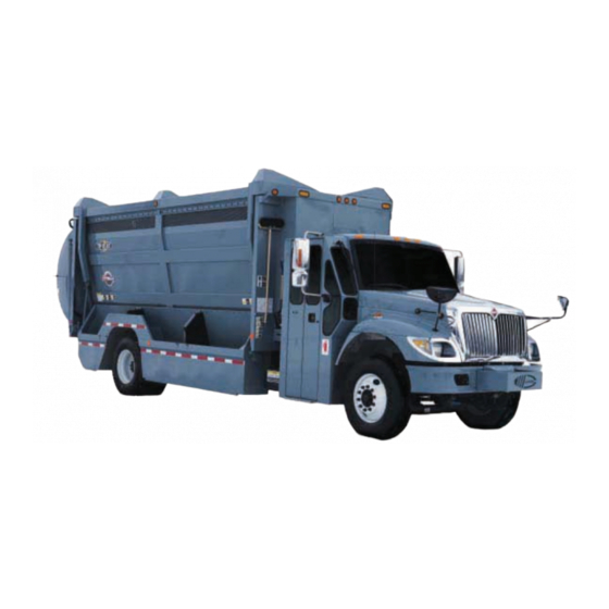
Summary of Contents for Labrie Top Select
- Page 1 Operator Manual Top Select Maintenance Manual...
- Page 2 ™ ELECT PERATOR ANUAL 5/1/09 : #90405 UMBER...
-
Page 4: Table Of Contents
Table of Contents Introduction Liability ..................... 1 Introducing the T ™ ..............1 ELECT To contact Labrie Plus ................2 Chapter 1 Safety Safety is Everyone’s Business .............. 3 Employer Responsibility ................ 4 Employee Responsibility ................ 4 General Safety ..................5 Do ..................... - Page 5 Safety features ..................36 Global Motion Sensors (optional) ........36 Troubleshooting and Maintenance ............37 Back Up Alarm ..............38 Body Safety Prop ..............39 Setting the Body Safety Prop ............. 39 Tailgate Safety Prop ............. 40 Setting the Tailgate Safety Prop ............40 Camera System (optional) ............
- Page 6 Dashboard Optional Indicators ............51 Tailgate Control ..................53 Loading Bucket Control ................ 54 Loading Bucket Rear Control ..........55 Loading Bucket Selector ............56 Hoist Control ..................57 Body Partition Controls ................ 57 Maximizer Control (Optional) ............... 58 Maximizer Partition Control ..........58 Light Controls ..................
- Page 7 Chapter 3 Operating the T ™ ELECT Daily Inspection ..................63 Approaching the Vehicle ............63 Visual inspection ..............64 Starting the Vehicle .............. 64 Cab Driving Control Inspection ........... 65 Cab Door Opening Procedure ..........66 Body Inspection Procedure ..........67 Inspection Sheet Example ...........
- Page 8 Body Unloading Procedure ..............88 Unloading Corrective Actions ..........90 Emergency Unloading Action ..........90 Maximizer Operation ................91 Initial Set Up For Body Partitions ........91 Using the Maximizer ............. 91 Unloading Rear Compartment ..........92 Unloading Front Compartment ..........94 End of the Day Cleaning ...............
- Page 9 Part #: 90405 viii...
-
Page 10: Introduction
NTRODUCTION IABILITY Labrie Environmental Group assumes no liability for any incidental, consequential or other liability from the use of this information. All risks and damages, incidental or otherwise, arising from use or misuse of the information contained herein are entirely the responsibility of the user. Although careful precaution has been taken in the preparation of this material, we assume no responsibility for errors or omissions. -
Page 11: To Contact Labrie Plus
O CONTACT ABRIE Address 3630 Stearns Drive Oshkosh, WI 54904 Toll free: 1-800-231-2771 Telephone: 1-920-233-2770 General Fax:1-920-232-2498 Sales Fax: 1-920-232-2498 Parts, service and warranty (during business hours, 7 am through 7 pm Central Standard Time) Technical support service (24 hours) Web Site: www.labriegroup.com E-mail:... -
Page 12: Chapter 1 Safety
AFETY Safety is always of prime importance when operating any type of equipment. All operators working with this unit must be aware of the safety practices and features detailed in this section. ’ AFETY IS VERYONE USINESS Personnel are not to use the equipment if they are not well acquainted with the operations as well as all the safety precautions of such operations. -
Page 13: Employer Responsibility
MPLOYER ESPONSIBILITY It is the employer’s responsibility to be familiar with and ensure that operation is in accordance with safety requirements and codes including all applicable regulations, including the Occupational Safety and Health Act (OSHA) and the American National Standards Institute (ANSI). It is also the employer’s responsibility to properly maintain all mobile equipment to meet all provincial/state and federal safety standards. -
Page 14: General Safety
The employee has the responsibility to report any damage or malfunction of the vehicle to his employer or his supervisor immediately. The employer will then take the necessary measures prior to the re-operation of the vehicle to insure its safe operation. Do not operate this equipment if there are any signs of damage or incomplete repairs. -
Page 15: Don't
’ Do not operate any unit while under the influence of alcohol, narcotics or other intoxicants. Do not talk on a cell phone and/or listen to loud music while driving. Cell phones and a loud radio can be a distraction that can have fatal consequences. Do not wear jewelry or loose clothing. -
Page 16: Safety Precautions
AFETY RECAUTIONS Do not operate this vehicle before having read and completely understood this manual and the safety labels on the vehicle. Maintenance personnel must also read and understand the Maintenance Manual for this vehicle (and the maintenance related information in this manual). In case of any doubt, see your supervisor for clarification. - Page 17 WARNING EAR SAFETY GLASSES GLOVES AND PROTECTIVE FOOTWEAR AT ALL TIMES WARNING O NOT CLIMB INTO BODY COMPARTMENTS USING THE SIDE BUCKET WARNING AKE SURE THAT ALL PEOPLE OR ANY OBSTRUCTIONS ARE SUFFICIENTLY CLEARED FROM THE LOADING BUCKET BEFORE MOVING IT AILURE TO DO SO MAY RESULT IN UNIT AND OR PROPERTY DAMAGES...
-
Page 18: Fire Extinguisher
WARNING RIOR TO CHANGING DRIVING POSITION STOP THE VEHICLE APPLY PARKING BRAKE PUSH EMERGENCY PUSH BUTTON AND STOP THE ENGINE ROPERLY ADJUST MIRRORS AND SET DRIVING CONTROL SWITCHES TO THE NEW DRIVING POSITION BEFORE STARTING THE ENGINE IRE EXTINGUISHER The fire extinguisher provided is 5 lbs (minimum capacity). It must be checked regularly by qualified personnel. -
Page 19: Safety Decals Location
These decals must be in place at all times. Report any damaged or missing decals to the proper authority. • Replacement decals can be ordered from Labrie Plus. Note:The following list is for reference only. It is not exhaustive. To get more details about your safety decals, please call Labrie Plus. -
Page 20: Location Of Decals On Tailgate
OCATION ECALS AILGATE 32307 47274 47266 47266 Part #: 90405... -
Page 21: Location Of Decals Inside Cab (Inter)
OCATION ECALS NSIDE NTER 43790 47426 43858 32311 47603 47276 43798 47440 47284 43792 43850 43786 43986 43972 47398 (not shown) 47400 47514* 43796 47394 47396 43956* Temporary handbrake control Right-hand side cab extension 43794 43982 * Height depends on truck configuration. Decals may vary. Part #: 90405... - Page 22 ), C OCATION ECALS NSIDE NTER ONTINUED 43864 43866 43890 Part #: 90405...
-
Page 23: Location Of Decals Inside Cab (M2)
(M2) OCATION ECALS NSIDE 43944 47426 32311 43798 43856 43986 43952 43868 47276 43858 43790 43786 47296 43792 43850 47603 43972 43794 97838 Right-hand side cab extension Temporary handbrake control Part #: 90405... - Page 24 (M2), C OCATION ECALS NSIDE ONTINUED 43864 43866 OR 43890 (optional) Part #: 90405...
-
Page 25: Location Of Decals On Console
OCATION ECALS ONSOLE 43878 47451 43880 (optional) 43888 43874 43862 43876 43906 43870 or 43872 47370 (when 43868 43900 (for L-H side 43952 equipped with driving position) two loading buckets) 47398 47400 43986 47284 47514* 47296 43796 43956 47394 47440 47396* 104539 * Height depends on truck configuration. -
Page 26: Illustration Of Decals
LLUSTRATION OF ECALS 9479 15489 15490 32307 or 32308 or 32311 Part #: 90405... - Page 27 43760 43786 43790 Part #: 90405...
- Page 28 43792 43794 43796 43798 Part #: 90405...
- Page 29 43816 43817 43850 Part #: 90405...
- Page 30 43856 43858 43862 43864 43866 43868 Part #: 90405...
- Page 31 43870 43872 43874 43876 43878 43880 43888 43890 Part #: 90405...
- Page 32 43900 43906 43920 Chassis with tag axle (optional) 43922 Chassis with tag axle (optional) 43944 Part #: 90405...
- Page 33 43950 43948 43952 43956 Part #: 90405...
- Page 34 43972 43958 43982 Part #: 90405...
- Page 35 43986 47260 43798 47262 47264 Part #: 90405...
- Page 36 47266 47268 47274 47276 Part #: 90405...
- Page 37 47284 47286 47290 47292 Part #: 90405...
- Page 38 47296 47300 47304 47320 Part #: 90405...
- Page 39 47324 47340 47350 47352 Part #: 90405...
- Page 40 47370 47374 47394 47396 Part #: 90405...
- Page 41 47398 47400 47402 47422 Part #: 90405...
- Page 42 47440 47426 47451 47514 47554 Part #: 90405...
- Page 43 47622 47564 47562 47603 47990 Part #: 90405...
- Page 44 97838 104092 The value depends on the truck model. 104539 Part #: 90405...
-
Page 45: Safety Features
AFETY FEATURES LOBAL OTION ENSORS OPTIONAL This OPTIONAL safety system is used to detect objects located behind the truck. This system is turned on by placing the transmission in reverse. WARNING HE OPERATOR MUST READ THE INSTALLATION MANUAL OF THE SYSTEM MANUFACTURER BEFORE USING THE SYSTEM The main components of this system are a control box , located in the cab, sensors, located on the rear bumper and the... -
Page 46: Troubleshooting And Maintenance
Control box WARNING ENSORS LENSES MUST BE KEPT CLEAN TO ENSURE PROPER OPERATION OF THE SYSTEM F THE LENSES ARE ALLOWED TO BECOME DIRTY SYSTEM RANGE WILL BE DECREASED The sensors are installed on the rear bumper and adjusted in order to obtain low coverage to ground. -
Page 47: Back Up Alarm
Note:Illustrations taken from the Installation Manual of Global Sensor Systems Inc. LARM The back up alarm sounds when the transmission is put into reverse, when the body raises or when the tailgate opens. Part #: 90405... -
Page 48: Body Safety Prop
AFETY The body safety prop ensures that the body will not lower when you are working beneath it. Body safety prop Setting the Body Safety Prop DANGER LWAYS BODY SAFETY PROP WHEN PERFORMING MAINTENANCE UNDER A RAISED BODY AILURE TO DO SO MAY RESULT IN SEVERE INJURY OR EVEN DEATH Start the engine. -
Page 49: Tailgate Safety Prop
Lower the body until it rests on the safety prop. Apply the lockout/tagout procedure before performing maintenance under the body. AILGATE AFETY Setting the Tailgate Safety Prop WARNING LWAYS TAILGATE SAFETY PROP WHEN WORKING UNDER A RAISED TAILGATE ROP MUST BE INSTALLED EVEN IF THE TAILGATE IS FULLY RAISED AILURE TO DO SO MAY CAUSE SERIOUS INJURY OR EVEN DEATH... - Page 50 Set the safety prop and install the safety pin. Safety pin Lower the tailgate onto the safety prop. Reverse the above instructions in order to store the safety prop. Part #: 90405...
-
Page 51: Camera System (Optional)
AMERA YSTEM OPTIONAL Optional monitor and cameras can be installed inside the cab and throughout the vehicle. The T ™ can be equipped ELECT with up to two (2) cameras. The operator can choose between the camera on the tailgate, the one located on street side mirror. -
Page 52: Cleanliness
LEANLINESS Cleanliness is part of safety. Clean all the truck’s lights and safety decals, so the operator, the surrounding pedestrians and vehicles will be aware of the truck at all times. Rake dirt out of the body once it has been unloaded. Some units are equipped with clean out tools installed at front-of-body (optional). -
Page 53: Shut Down Procedure
ROCEDURE If the truck is parked for an extended period of time, follow the chassis manufacturer’s shutdown procedure as well as maintenance requirements and ensure the following procedure: Park on a hard and level ground. Apply the parking brake. Make sure that all moving parts are in their “home “ position (tailgate, loading bucket, body, etc.). -
Page 54: Driving Speed
RIVING PEED If the cab of the vehicle has been modified by Labrie Environ- mental Group (right-hand side driving position) for door-to-door waste collection, the maximum speed limit while driving at the right-hand side is, if permitted, 20 mph. (32 km/h). Therefore, it is recommended to drive the vehicle on the left-hand side for any long distance driving. - Page 55 Adjust mirrors properly. Right-hand side Convex mirror field of view mirror Operator Right-hand side Bus type Camera mirrors (on driving position view conventional (optional) cabs only) Convex Left-hand side mirror mirror field of view Convex Right-hand side mirror mirror field of view Bus type Left-hand side mirrors (on...
-
Page 56: Brake System
AND MAKE SURE THERE IS NO ONE NEARBY Temporary Handbrake Note:This section applies only to cabs that have been modified by Labrie Environmental Group. If your cab has not been modified by Labrie Environmental Group, refer to cab manufacturer. The temporary handbrake is located near the curb side door (on console for some models). -
Page 57: Pump Switch
Always stop the vehicle using the footbrake, then apply the temporary handbrake (for short stops) or the parking brake (for longer stops) before leaving the vehicle. A medium application of pressure on the footbrake is normally sufficient to stop the truck. If the brakes are always used at full capacity, there will be premature wear to the rear axle brake components and tires. -
Page 58: Emergency Stop Control
(refer to “Lockout/Tagout Procedure” on page 43). EUTRAL WITCH The auto-neutral switch (standard on Labrie cab conversion) allows the transmission to shift from Drive to Neutral Auto-neutral automatically without using the shifter lever or shifter keypad. - Page 59 Apply the temporary handbrake. To disable the auto-neutral function: Release the temporary handbrake. Step on the foot brake. The transmission will shift back to Drive. If the transmission does not shift to Neutral when releasing the temporary handbrake: Footbrake Apply the footbrake. Reengage the temporary handbrake.
-
Page 60: Over Speed Protection Mode
ASHBOARD PTIONAL NDICATORS The right-hand side dashboard of cabs modified by Labrie Environmental Group can be equipped with optional gauges and indicators that allow the operator to monitor the status of the engine and other systems on the vehicle. The dashboard can be equipped with gauges such as oil pressure, battery charge, engine temperature and transmission temperature. - Page 61 Alternator Transmission indicator temperature (optional) Air pressure (optional) indicator Temperature indicator (optional) Speedometer Oil pressure (optional) Part #: 90405...
-
Page 62: Tailgate Control
AILGATE ONTROL Located on the console, the tailgate control lever has a spring ac- tivated sleeve which locks the handle to prevent any accidental opening of the tailgate. The sleeve needs to be pulled up before moving the lever to open or close the tailgate. CAUTION Tailgate control lever... -
Page 63: Loading Bucket Control
OADING UCKET ONTROL The loading bucket control joystick is located inside the cab. Note:This joystick can also be located between the cab and the body, depending on the chassis model. Loading bucket joystick inside the cab When there is a loading bucket joystick outside the cab, it is automatically equipped with a deadman button. -
Page 64: Loading Bucket Rear Control
Loading Bucket Rear Control For operator convenience, a rear control joystick is available as an option for the loading bucket. If your T ™ is ELECT equipped with this device, you can empty the loading bucket from the back of the truck as well as from the front. Loading bucket rear control WARNING... -
Page 65: Loading Bucket Selector
Loading Bucket Selector Some T ™ units are equipped with two loading ELECT buckets. In order to prevent both roofs from colliding with each other, it is necessary to select one of the loading buckets, using the selector switch located on the console. CAUTION AKE SURE THAT BOTH ROOFS ARE COMPLETELY DOWN BEFORE USING THE SELECTOR SWITCH... -
Page 66: Hoist Control
OIST ONTROL The body hoist control lever is located on the cab console. The lever has a spring activated sleeve which locks the handle to pre- vent any accidental body hoist operation. This lever has to be moved to the left or right in order to raise or lower the body. Hoist control lever When the body is raised, the Tailgate unlocked or body raised... -
Page 67: Maximizer Control (Optional)
AXIMIZER ONTROL PTIONAL When the unit is equipped with a Maximizer, the Maximizer control joystick is located inside the cab. Note:This joystick can also be located between the cab and the body, depending on the chassis model. As soon as the Maximizer joystick is activated, the engine automatically accelerates to 1500 RPM. -
Page 68: Light Controls
IGHT ONTROLS Work Lights Switch (optional) When installed, this switch activates and deactivates the work lights. • Shift the switch up to illuminate the work lights. • Shift the switch down to turn off the work lights. Flashing Lights Switch (optional) This switch activates and deactivates the flashing lights. -
Page 69: Warning Lights
ARNING IGHTS Neutral Light Indicator (Green) Located on the dashboard, this light turns on when the transmission is in Neutral position. Temporary Handbrake Light (Red) Located on the dashboard, this light turns on when the temporary handbrake (or service brake) is applied. Part #: 90405... -
Page 70: Pto Light (Red)
PTO Light (Red) Located next to the pump switch, this light turns on when the hydraulic pump is engaged. Auto-Neutral Light (Red) Located on the console, the Auto-neutral light turns on when the Auto-neutral system is engaged. Tailgate, Roof Or Body Raised Warning Light (Red) Located on the console, this light has three functions. -
Page 71: Tailgate Fully Opened Light (Optional)
Tailgate Fully Opened Light (Optional) This light (if equipped) turns on when the tailgate is fully open, so you can raise the body for dumping. Body Raise Allowed Indicator (Optional) This warning light turns on when the air suspension has been dropped. -
Page 72: Chapter 3 Operating The Top Select
PERATING THE ™ ELECT The different methods, procedures and necessary actions to operate the T ™ are presented in this section.. ELECT WARNING LWAYS READ UNDERSTAND PERATOR ANUAL BEFORE OPERATING THE EQUIPMENT Before operating the T ™, the operator must be ELECT completely familiar with all safety procedures, location, operation and function of all controls and indicators related to... -
Page 73: Visual Inspection
Visual inspection Before starting the vehicle, the operator MUST perform a visual inspection of the truck. Ensure the engine is not running and the parking brake is set. Ensure the cleanliness of lamps, safety labels, camera lenses, mirors, windows, and the vehicle in general. Ensure that safety equipment is present (i.e. -
Page 74: Cab Driving Control Inspection
Report any defective system to the maintenance personnel. Cab Driving Control Inspection Note:This section applies only to cabs that have been modified by Labrie Environmental Group. Enter the right-hand side extension and operate the right-hand side driving controls. Report any defective system to maintenance personnel. -
Page 75: Cab Door Opening Procedure
Cab Door Opening Procedure This section applies only to cabs that have been modified by Labrie Environmental Group. To open the curb side door: Unlock and open the curb side cab door. Inside the folding door, locate the sliding lock. -
Page 76: Body Inspection Procedure
Lock the folding door using the latch located behind the cab. Latch To release, use the release mechanism located inside the cab. Release mechanism Body Inspection Procedure Exit the cab to continue your inspection. Bring a rag along to clean all accessible lights, stickers, camera lens, etc. Look for mechanical problems: rollers, hinges, door lock mechanisms, wear items, etc. - Page 77 Check the chassis area, fuel tank and air tanks (air tanks must be drained every day), wheels for leaks, cracks or other type of problems. At the front of the unit, check lights, mirrors and pump (if not PTO mounted). Go around and check lights, clean camera, labels, lights, etc.
-
Page 78: Inspection Sheet Example
Inspection Sheet Example The following is an example of an inspection sheet. The operator MUST follow the inspection sheet provided by his employer. If the employer doesn’t have an inspection sheet, ask their permission before using this example. Part #: 90405... -
Page 79: Loading And Unloading
Note:The procedure herein relating to the use of the auto- neutral and the temporary handbrake applies only to cabs modified by Labrie Environmental Group. If your cab has not been modified by Labrie Environmental Group, please refer to your cab manufacturer recommendations. -
Page 80: For Cabs That Are Not Equipped With A Curb Side Extension
Step off the vehicle. To step out, keep a good hold on the vehicle until you have assured yourself of a good stand on solid ground. DANGER O NOT LEAVE THE VEHICLE UNTIL IT IS COMPLETELY STOPPED AILURE TO DO SO MAY CAUSE SERIOUS INJURY OR EVEN DEATH Load the bucket (refer to “Bucket Loading Procedure”... -
Page 81: Loading Bucket
Release the temporary handbrake or parking brake. Engage the transmission shifter to Drive. Drive to the next pick up point. Loading Bucket Loading Bucket Specifications 16-inch loading bucket: • Volume: 2.23 yd³ • Maximum weight: 1000 lbs (453 kg) 18-inch loading bucket: •... -
Page 82: Safety While Using The Loading Bucket
Safety While Using the Loading Bucket WARNING LWAYS KEEP THE WARNING LIGHTS AND OR FOUR WAY FLASHERS WHEN COLLECTING RECYCLABLE MATERIALS DANGER EVER ATTEMPT TO GET INSIDE THE BODY FROM THE ROOF TO MAKE MORE ROOM INSIDE THE BODY OR FOR ANY OTHER REASON EVERE INJURY OR DEATH MAY OCCUR... -
Page 83: Bucket Loading Procedure
CAUTION ATERIAL SUCH AS PAPER AND CARDBOARD SHOULD BE LOADED AT THE REAR OF THE TRUCK SING THE FRONT COMPARTMENT MIGHT CAUSE DUMPING PROBLEM Bucket Loading Procedure Before loading the body, read the following loading procedure. Body loading procedure: Make sure all the partitions are secured. Make sure the overhead clearance is sufficient and that the roof is clear of any obstacles. -
Page 84: Loading Bucket Safety Pins
Raise the bucket using the bucket joystick (refer to “Loading Bucket Control” on page 54). Note:If the joystick is equipped with a deadman button, push and maintain this button to operate the loading bucket. Loading Bucket Safety Pins The loading bucket can be locked and secured at the end of its tracks. - Page 85 To install loading bucket safety pins: Make sure the body is completely empty. Make sure the loading bucket is empty. Engage the hydraulic system. Lift the bucket until it reaches the end of its stroke. Open the tailgate and install its safety prop (refer to “Tailgate Safety Prop”...
- Page 86 • Insert the pins in their corresponding holes so they are both in locked position. Locking pin hole • Make sure both pins are firmly held in place. Loading bucket safety pin in locked position Note:The rear loading bucket safety pin is located near the curb side tailgate hinge.
- Page 87 operator has to cross body partition(s) using partition door(s). Body partition door When service is completed, remove the safety pins and completely lower the loading bucket. Part #: 90405...
-
Page 88: Loading Bucket Partition Adjustment
Loading Bucket Partition Adjustment The loading bucket is equipped with “readily movable” partitions. The bottom lock is held by a vertical pin going through the bottom of the bucket while two side pins hold them at the top. Loading bucket partitions adjustment procedure: Pull the handle. -
Page 89: Body Partitions Adjustment
Note:Align the body and loading bucket partitions so that no cross contamination can occur when unloading the side bucket. Body Partitions Adjustment The Labrie T ™ can be equipped with up to seven (7) ELECT air-operated opening body partitions, giving eight (8) adjustable compartments for recyclable materials. - Page 90 Slide off the partition’s top locking pin. Upper locking mechanism Release floor locking pins using the manual release system located in the body. 1- Pull the lever (manual operation) Block the lever Locking mechanism Locking mechanism in unlocked position Part #: 90405...
- Page 91 Note:If the partition needs to be moved a long distance, it may be necessary to disconnect the partition pneumatic hose (located on the roof) and plug it into another pneumatic coupler. Each partition (if more than one) has its own pneumatic hose. There may be more than one coupler for a partition.
-
Page 92: Loading Corrective Actions
Loading Corrective Actions If the loading bucket does not cycle: Ensure the hydraulic system is engaged (PTO switch to On). Check bucket selector switch (for units equipped with two buckets). Use another loading bucket joystick (if more than one installed). Is the loading bucket joystick equipped with a deadman button? If so, make sure to press and hold this button to operate the loading bucket. -
Page 93: Loading Roller Carts
Recycling OADING OLLER ARTS ™ loading bucket can also load roller carts, using an ELECT optional automatic latching system. In order to secure roller carts to the loading system, an optional automatic latching system located at the bottom of the bucket will grab the roller cart as the bucket starts to move up. -
Page 94: Roller Cart Latching Procedure
Upper latching American style support roller cart Lower latching mechanism Roller Cart Latching Procedure To latch a roller cart on the loading bucket: Note:Some units are equipped with more than one latch in order to allow multiple roller cart collection. Part #: 90405... - Page 95 Push the automatic latching system pin, which is located between the cab and the body. Turn the pin counterclockwise about a ¼ turn. This activates the automatic latching system. Bring the roller cart against the loading bucket. Slowly raise the bucket(s) and make sure all lower latches are properly locked.
- Page 96 Once the roller cart(s) have been emptied, lower the loading bucket. The lower latch will unlock as soon as the cart reaches the ground.. CAUTION LWAYS BE CAUTIOUS AND WATCH FOR AN IMPROPRELY ATTACHED CART THAT OULD FALL OFF DANGER “...
-
Page 97: Body Unloading Procedure
NLOADING ROCEDURE Drive the vehicle to the desired site. Ensure the vehicle is on safe, stable and level ground. Check for overhead clearance before opening the tailgate and raising the body. CAUTION HE OVERHEAD CLEARANCE VARIES ACCORDING TO THE BODY VOLUME LEASE REFER TO THE SAFETY DECAL LOCATED IN THE CAB IN ORDER TO KNOW THE EXACT BODY HEIGHT WHEN COMPLETELY RAISED... - Page 98 Release the second partition and repeat the procedure. Perform the same procedure for all partitions. When unloading is completed, lower the body and lock the partitions back in place. The operator has to go inside the body to make sure that all partitions are locked in place.
-
Page 99: Unloading Corrective Actions
CAUTION EVER RAISE THE BODY WHEN THE TAILGATE IS CLOSED BUMPER WILL NOT CLEAR THE GROUND Unloading Corrective Actions If the body does not raise: Make sure the hydraulic system is engaged (PTO switch On). Check fuses inside the console. Make sure the air pressure has reached 70 PSI. -
Page 100: Maximizer Operation
AXIMIZER PERATION Follow these instructions in order to gain maximum performance of the Maximizer option. Initial Set Up For Body Partitions Use the position marker for proper alignment Set the bucket partitions and Maximizer to obtain your best- known volume distribution before starting recyclable collection (e.g. -
Page 101: Unloading Rear Compartment
Maximizer cycles until both compartments are fully loaded and no more room is available. REVERSE FORWARD Air control joystick CAUTION O NOT USE THE AXIMIZER AS INTENSIVELY AS A PACKER LASS WILL PREMATURELY WEAR THE RAILS Unloading Rear Compartment To unload rear compartment: Drive the vehicle to the desired site. - Page 102 Remove tailgate safety pin. Tailgate safety pin Fully raise the tailgate. Raise the body. The material will slide out. Note:As you raise the body, you can throttle up the engine to raise it completely up faster. Do not accelerate the engine for the last section of the hoist to prevent a sharp stop at the end of the cylinder extension.
-
Page 103: Unloading Front Compartment
Loss of usable volume in loading bucket UNLOADING REAR COMPARTMENT Unloading Front Compartment To unload front compartment: Drive the vehicle to the desired site. Ensure the vehicle is on safe, stable and level ground. Check for overhead clearance before opening the tailgate and raising the body. - Page 104 Remove tailgate safety pin. Tailgate safety pin Fully raise the tailgate. Raise the body. Note:As you raise the body, you can throttle up the engine to get it completely up faster. Do not accelerate the engine for the last section of the hoist to prevent a sharp stop at the end of the cylinder extension.
-
Page 105: End Of The Day Cleaning
When the unloading is completed, lower the body and relock the Maximizer swing door. From the back of the unit, make sure the swing door is properly locked. Close the tailgate and secure the safety pin. Swing door UNLOADING FRONT COMPARTMENT ND OF THE LEANING Body Weekly Cleaning... -
Page 106: Loading Bucket Weekly Cleaning
Using a shovel or a broom, remove as much material as possible. Clean the rest using pressurized water. Once the first partition is clean, release its locks in order to evacuate the water (refer to “Body Partitions Adjustment” on page 80). Clean the second section. -
Page 107: Chassis Weekly Cleaning
Chassis Weekly Cleaning Chassis weekly cleaning procedure: Start the engine. Raise the body until the safety prop is free to tilt under the body. Release the safety prop using the prop handle (refer to “Setting the Body Safety Prop” on page 39). Apply the lockout/tagout procedure (refer to “Lockout/ Tagout Procedure”... - Page 108 Move the Maximizer towards the tailgate in order to retract the cylinder. Stop the hydraulic pump and the engine. Open the Maximizer access door. Clean the section located between the cab and the Maximizer using pressurized water. Open the cylinder access traps (3) by removing their bolts (2 for each trap) and clean thoroughly.
-
Page 109: Hydraulic Oil Leak
YDRAULIC In case of an hydraulic oil leak: Disengage the hydraulic system and stop the truck engine. Close the valve located on the hydraulic tank. Identify the cause of the leak. Call your maintenance facility and report your findings. Before you restart the engine, make sure the pump will not turn and pump any hydraulic oil. - Page 110 When the pump system has no clutch: CAUTION N THE CASE OF HYDRAULIC SYSTEM LEAK DISCONNECT THE DRIVE SHAFT LOCATED BETWEEN THE PUMP AND THE ENGINE BEFORE DRIVING THE VEHICLE TO BE REPAIRED Part #: 90405...
- Page 111 Part #: 90405...
- Page 112 3630 Stearns Drive, Oshkosh, WI 54904 Toll free: 1-800-231-2771 Telephone: 1-920-233-2770 General Fax: 1-920-232-2496 Sales Fax: 1-920-232-2498 Mailing Address: P.O. Box 2785 Oshkosh, WI 54903-2785 Parts, Service and Warranty (during business hours 7:00 AM to 7:00 PM Central Standard Time) Technical Support Service (24 hours) Part # 90405...
Need help?
Do you have a question about the Top Select and is the answer not in the manual?
Questions and answers