
Subscribe to Our Youtube Channel
Related Manuals for Labrie EXPERT 2000 2002


Summary of Contents for Labrie EXPERT 2000 2002
- Page 1 OPERATOR’S MANUAL WITH COOL HAND & HELPING HAND SUPPLEMENT PRODUCTIVITY THROUGH INNOVATION RELEASE: July 2002 Part #47029...
- Page 3 Any time that you have a problem with a Labrie unit, you should contact your vendor first. He should be able to provide you with the proper help required (parts or technical advice).
-
Page 5: Table Of Contents
LABRIE EXPERT 2000 OPERATOR’S MANUAL Table of contents INTRODUCTION ......................9 OBJECTIVE ........................9 USEFUL ADDRESS AND PHONE NUMBERS .............. 9 SAFETY AND OPERATIONAL PRECAUTIONS ............. 11 GENERAL PRECAUTIONS ................... 11 GENERAL RESPONSIBILITIES OF THE EMPLOYER ..........13 GENERAL RESPONSIBILITIES OF THE EMPLOYEE ..........13 LOCKOUT / TAGOUT PROCEDURE ................ - Page 6 LABRIE EXPERT 2000 OPERATOR’S MANUAL Table of contents CONTROLS DESCRIPTION ..................31 3.2.1 ENGAGING THE PUMP ....................31 3.2.2 PACKER CONTROL STATIONS ................... 32 3.2.3 EMERGENCY STOP CONTROLS ................32 3.2.4 START CYCLE CONTROL .................... 32 3.2.5 RETRACTION CONTROL ..................... 32 3.2.6...
- Page 7 LABRIE EXPERT 2000 OPERATOR’S MANUAL Table of contents LOADING, COMPACTING AND UNLOADING ............39 3.4.1 PLANNING YOUR ROUTE ................... 39 3.4.2 SAFETY WHEN USING PACKING SYSTEM ............. 39 3.4.3 HOPPER DESCRIPTION ....................40 3.4.4 PACKING RAM DESCRIPTION ................... 40 3.4.5 CRUSHER PANEL ......................
-
Page 9: Introduction
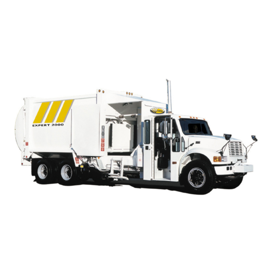
(418) 831-8250 truck operated by only one person, as was the previous version, the LABRIE 200. After many Fax: years of experience with the LABRIE 200 side Sales Dept.: (418) 831-5255 loader, Labrie Equipment has developed the Service & Warranty: (418) 831-1673... -
Page 11: Safety And Operational Precautions
COULD result supervisor for clarification. in personal injury or death of the user or others. The Labrie Expert 2000 and Automizer units equipped with a Cool Hand or Helping Hand lifting arms are primarily CAUTION... - Page 12 12. When the vehicle is parked, the parking In such a case Labrie must be informed brake must be applied. of every and all units with a Cool Hand or Helping Hand operated by more than 13.
-
Page 13: General Responsibilities Of The Employer
4. Any breaks or malfunctions that can affect WARNING the safe usage of the vehicle must be repaired before the vehicle is to be used 16. While collecting garbage, watch for again. explosive objects, such as television tubes, fluorescent tubes, cans under 5. -
Page 14: Lockout / Tagout Procedure
• Apply parking brake; configuration. Refer to Labrie part and service • Turn off engine; department for replacement. • Remove key from ignition switch;... - Page 15 2.5.1 LOCATION OF LABELS ON BODY #15492 #32708 #9256 #10782 #20142 #20154 #20148 #14900 #11271 1: LOCATED ON BOTH SIDE OF THE BODY 2: OPTIONAL ONLY GENERAL SAFETY PRECAUTIONS...
- Page 16 2.5.1 LOCATION OF LABELS AND LOGOS ON BODY #CID01250 #CID01260 #10782 #10776 #10774 #10775 #21439 1: Same location on the left-hand side EXPERT 2000...
-
Page 17: Location Of Labels And Logos On Tailgate
2.5.2 LOCATION OF LABELS AND LOGOS ON TAILGATE #32307 #09255 #09255 #9252 GENERAL SAFETY PRECAUTIONS... -
Page 18: Location Of Labels Inside Cab
2.5.3 LOCATION OF LABELS INSIDE CAB 20140 9250 20177 10781 12338 9246 12369 20428 20425 DASH VIEW EXPERT 2000... - Page 19 2.5.3 LOCATION OF LABELS INSIDE CAB NOTE: THE LOCATION OF LABELS INSIDE CAB MAY CHANGE DEPENDING ON WHAT TYPE OF CHASSIS AND/OR SPECIAL FEATURES INSTALLED ON THE VEHICLE. 11733 21137 18334 12104 12308 DASH VIEW GENERAL SAFETY PRECAUTIONS...
- Page 20 2.5.3 LOCATION OF LABELS ON CONSOLE 10698 11537 10496 10497 12312 12311 10494 12338 32260 EXPERT 2000...
-
Page 21: Illustrations Of Labels
2.5.4 ILLUSTRATIONS OF LABELS 8790 9246 9247 GENERAL SAFETY PRECAUTIONS... - Page 22 2.5.4 ILLUSTRATIONS OF LABELS 9252 9255 9256 EXPERT 2000...
- Page 23 2.5.4 ILLUSTRATIONS OF LABELS 10774 10775 10776 GENERAL SAFETY PRECAUTIONS...
- Page 24 2.5.4 ILLUSTRATIONS OF LABELS 10782 11271 11427 EXPERT 2000...
- Page 25 2.5.4 ILLUSTRATIONS OF LABELS 11497 11733 12104 12116 GENERAL SAFETY PRECAUTIONS...
- Page 26 2.5.4 ILLUSTRATIONS OF LABELS 12245 12247 12299 CID01250 CID01260 EXPERT 2000...
-
Page 27: Operator's Manual
OPERATOR’S MANUAL open. (See section 3.2.1 “Engaging Hydraulic System”). Once the engine is started, wait for the air GENERAL PRECAUTIONS pressure to reach 90 PSI, you can then operate the equipment. Never operate machinery while wearing jewelry or loose clothing which may catch on 3.1.2 FIRE PROTECTION moving parts. -
Page 28: Shutdown
3.1.4 SHUTDOWN 3.1.6 DRIVING SPEED When you park the truck for an extended The vehicle is driven on the right-hand side for period of time, follow the truck manufacturer door to door waste collection, and the requirements as well as the maintenance maximum speed limit by law is 20 m.p.h. -
Page 29: Brake System
The temporary handbrake is located near the WHEEL: right-hand side door (when the cab conversion is done by Labrie Equipment) and operates the • Drive to waste collection district service braking system of the truck (Figure and stop the vehicle;... -
Page 30: Auto-Neutral (Optional)
3.1.8 AUTO-NEUTRAL (optional) Note 1: The PTO will be engaged if RPM is lower than Two auto-neutral system configurations are 900. This configuration allows the operator to available. The first one is offer on units pack at any given RPM while the truck is equipped with an Allison electronic moving. -
Page 31: Controls Description
CONTROLS DESCRIPTION WARNING 3.2.1 ENGAGING THE PUMP IT IS VERY IMPORTANT NOT The pump system is engaged by the rocker TO LET THE PUMP RUN DRY switch located on the console. A red pilot light (WITHOUT OIL) OR TO TURN comes on to indicate that the hydraulic system THE BALL VALVE (FIGURE is engaged (Figure #3.5). -
Page 32: Packer Control Stations
3.2.2 PACKER CONTROL STATIONS 3.2.5 RETRACTION CONTROL There could be as many as three control stations The yellow button will retract the packing ram (figure #3.7) for the packer system. The right- (when the selector switch is in the proper hand side station, which is standard, the cab position). - Page 33 PACKER CONTROL STATION FIGURE #3.7 OPERATOR’S MANUAL...
-
Page 34: Console Selector Control
3.2.8 CONSOLE SELECTOR CONTROL 3.2.10 HOIST CONTROL This selects the proper packer control station. The hoist control is located on the cab console Only one station is in operation at a given (Figure #3.8). time, however, the red buttons are always 3.2.11 STANDARD TAILGATE CONTROL operational whatever the position set on the selector switch (Figure #3.8). -
Page 35: Dual Tailgate Control
3.2.12 DUAL TAILGATE CONTROL 3.2.14 OPTIONAL CONTROLS An air selector switch allows you to choose Different optional controls could be installed between the right or the left tailgate. The same on the Expert 2000. They are usually located joystick, with a lock is used for both tailgates on the cab console and are identified with (Figure #3.9). -
Page 36: Crusher Panel Control
3.2.15 CRUSHER PANEL CONTROL STANDARD CRUSHER (if installed) PANEL CONTOL The control for the crusher panel is fully manual (standard unit) and it is located directly on the main valve on the right-hand side of the unit. Optional remote air joysticks can be installed. They are installed inside the cab (right-hand side) and on the left-hand side of the body when a crusher panel control is required on the... -
Page 37: Daily Inspection
TRUCK STARTING PROCEDURE: • Put transmission shifter “neutral”; • Parking brake is “On”; • Hydraulic system is “Off”; CART TIPPER CONTROL • Start engine; CHUTE CONTROL • Engage the hydraulic system using the PTO switch on the console(the air pressure has to be at a minimum of 90 PSI);... -
Page 38: Body Inspection Procedure
3.3.3 BODY INSPECTION PROCEDURE 3.3.4 CAB DRIVING CONTROLS INSPECTION PROCEDURE Exit the cab to continue your inspection. Bring Enter the right-hand side extension and operate a rag along to clean all accessible lights, the right-hand side driving controls: Report stickers, camera lens etc. Check for mechanical any defective system to maintenance personnel. -
Page 39: Loading, Compacting And Unloading
LOADING, COMPACTING AND DANGER UNLOADING 3.4.1 PLANNING YOUR ROUTE NEVER ATTEMPT TO REACH INSIDE THE HOPPER AREA With a side loading refuse unit it is important W H E N E I T H E R T H E to plan your pick ups properly. You have to COMPACTING BLADE OR THE know your route and what type of refuse and/ C R U S H E R... -
Page 40: Hopper Description
3.4.3 HOPPER DESCRIPTION FLOATING PANEL FOLLOWER PANEL The Expert 2000 side loader refuse truck has a standard hopper with a swept volume of 1.44 cubic yards. That swept volume is achieved by an 18 inch high packing blade sliding on a 52 inch stroke. -
Page 41: Crusher Panel
3.4.5 CRUSHER PANEL The crusher panel is an option that may be installed on the vehicle. If it is installed we suggest you to use it only for bulky items and breaking the load. In many cases, unnecessary use will slow down the operation. Bulky items can be maintained in place with the crusher panel while the packing ram crushes them. -
Page 42: Recycling Boxes
3.4.7 RECYCLING BOXES CRUSHER PANEL OPERATION When your district has a recycling program (with the blue recycling boxes, and you are using our commingle side loader, it is suggested that you use the closest side of the hopper to the boxes to unload them, or else it could probably overwork the operator in a shorter BODY period of time. -
Page 43: Roller Carts
3.4.8 ROLLER CARTS CART TIPPER OPERATION Roller carts are generally used for garbage and unload themselves in the center of the hopper to prevent spillage on either side of the hopper. They are provided with a hook up system opposite to the wheels and cover’s hinge. This hook up system should engage the cart tipper adequately, if it is the appropriate type to fit the roller cart. -
Page 44: Breaking The Load
3.4.9 BREAKING THE LOAD EARLY JAMMING OF PACKING RAM At a certain point during the standard loading it will seem like no more refuse can get inside the body. You may think that the body is full but it is not the case most of the time. What you are facing at that point is a compressed line of garbage between the tailgate and the packing ram itself. -
Page 45: Standard Collection Procedure
3.4.10 STANDARD COLLECTION STANDARD COLLECTION PROCEDURE PROCEDURE To step out of the right-hand side cab extension • Stop the truck by applying foot follow this procedure: brake; • Wait for the truck to be completely stopped; • Put the transmission to neutral; •... -
Page 46: Cab Folding Door
3.4.11 CAB FOLDING DOOR SLIDING LOCK DOOR OPENING PROCEDURE • Unlock and open right-hand side door (Figure #3.21); • Inside folding door, locate the sliding lock (Figure #3.22); • Follow step 1 to 3 (Figure #3.23); • Fold door by pushing on the center of the door;... - Page 47 DOOR LATCH FIGURE #3.24 RELEASE HANDLE FIGURE #3.26 LATCH FIGURE #3.25 Lock the door using the latch behind the cab (figure #3.25). OPERATOR’S MANUAL...
-
Page 48: Loading Corrective Actions
3.4.12 LOADING CORRECTIVE ACTIONS 3.4.13 EMERGENCY ACTIONS HYDRAULIC OIL SPILL PACKING RAM WILL NOT CYCLE: • Disengage the hydraulic system and • Ensure the hydraulic system is stop the truck engine; engaged; • Close all the valves on the hydraulic •... -
Page 49: Pack On The Go
3.4.14 PACK ON THE GO STANDARD UNLOADING PROCEDURE It may be useful to expedite your work and be more efficient to “pack on the go”. As you are • Drive the vehicle to the desired site. finished with loading the hopper and instead •... - Page 50 The commingle versions of the EXPERT 2000 WARNING have a different unloading procedure because two rear doors have to be opened in the right sequence. ON ALL COMMINGLE NEVER BACKUP THE TRUCK VERSIONS, THE LEFT-HAND SIDE WITH THE BODY IN THE RAISED COMPARTMENT HAS TO BE OPENED POSITION.
- Page 51 YOU ARE NOW DRIVING AN WARNING U N B A L A N C E D V E H I C L E : REDUCE SPEED AND DO NOT UNLOADING PROCEDURE COVER LARGE DISTANCES. (SINGLE TAILGATE WITH INSIDE SWING DOOR CONFIGURATION). •...
-
Page 52: Unloading Corrective Actions
DANGER ALWAYS USE THE TAILGATE S A F E T Y P R O P W H E N WORKING UNDER A RAISED TAILGATE. PROP CAN BE I N S T A L L E D E V E N I F T H E TAILGATE IS IN THE FULLY RAISED POSITION. -
Page 53: Unloading Emergency Actions
3.4.17 UNLOADING EMERGENCY ACTIONS CAUTION If the truck starts to sink on one side as you unload: BODY DOES NOT RAISE • Ensure the hydraulic system is DANGER engaged; • Check fuses; UNLOADING EMERGENCY • Make sure the air pressure is above ACTIONS 90 PSI;... -
Page 54: Hopper Daily Cleaning
3.4.18 HOPPER DAILY CLEANING CLEANING BEHIND PACKER BLADE Cleanliness is part of safety, ensure the equipment works properly by removing any compacted garbage in the packer area, and clean all the truck lights, warning lights and safety stickers so you and the surrounding pedestrians and vehicles, will be safe around the vehicle at all times. -
Page 55: Chassis Daily Cleaning
3.4.19 CHASSIS DAILY CLEANING CHASSIS DAILY CLEANING PROCEDURE SAFETY PROP RELEASE HANDLE • Tag out; • Set safety prop (Figure #3.35); • Clean with pressurized water between body and frame; • Clean rear of cab; • Start truck, lift body, set off safety prop (Figure #3.36);... -
Page 56: Cool Hand Automated Unit Operation
KEEP AWAY FROM ANY METAL even cause injury or death. PARTS. The Labrie automated arm has been designed to only grab roller carts. Do not attempt to grab or lift up anything else except roller carts. WARNING... -
Page 57: Loading Procedure
3.5.2 LOADING PROCEDURE INITIAL POSITION IN THE HOPPER SECTION LOADING PROCEDURE • Stop the vehicle so that the arm is lined up with the roller cart; INNER BOOM DOWN (12 O'CLOCK) • The distance between the vehicle and the roller cart has to be 4 to 9 feet (1.25 M. - Page 58 Open grabber halfway down before it hits the roller cart. PUSH RIGHT TO OPEN GRAB FIGURE #3.38 EXPERT 2000...
-
Page 59: Troubleshooting Quick Reference
3.5.3 TROUBLESHOOTING QUICK REFERENCE WARNING When an electrical failure occurs and prevent NEVER DRIVE THIS VEHICLE IF the operator from retracting the arm, the THE AUTOMATED ARM IS NOT following procedure can be applied. FULLY RETRACTED TO ITS RESTING POSITION. (THE RED a) Apply the parking brake and put the L I G H T C O M E S O N I F T H E transmission in neutral. -
Page 60: Location Of Labels And Logo
3.5.4 LOCATION OF LABELS AND LOGO Location of special labels for the automated arm, body and cabs. FIGURE #3.40 COOL HAND 20414 21137 20140 21111 12104 20140 12308 20245 21137 11733 20414 20177 9250 20221 9246 11271 20428 9247 20177 FIGURE #3.41 FIGURE #3.42 EXPERT 2000... -
Page 61: Illustration Of Labels And Logo
3.5.5 ILLUSTRATION OF LABELS AND LOGO 12308 20414 20177 11271 21111 20221 9246 20425 11733 20428 9247 9250 FIGURE #3.43 21137 OPERATOR’S MANUAL... -
Page 62: Helping Hand Automated Arm Operation
HELPING HAND AUTOMATED WARNING ARM OPERATION 3.6.1 DESCRIPTION NEVER DRIVE THIS VEHICLE IF THE AUTOMATED ARM IS NOT The HELPING HAND automated arm was F U L L Y R E T R A C T E D I N I T S designed to be used on narrow streets where R E S T I N G P O S I T I O N . -
Page 63: Start Up
3.6.3 START UP Figure #3.45 shows basic movements of the arm while moving the joystick. The joystick is Refer to section 3.3.2 “Truck starting also provided with a push button which is procedure” of the Expert 2000 Operator’s located on top of the joystick. This push button Manual. - Page 64 LOADING PROCEDURE LIFT-UP • Stop the vehicle so that the arm is lined up with the roller cart. The distance between the roller cart and the truck has to be from less than a foot (30cm) to a maximum of 6 feet (1.83m.);...
- Page 65 HELPING HAND MIN. / MAX. REACH MIN. REACH: LESS THAN A FEET MAX. REACH: 72 INCHES (1,83m) 72” INCHES (1,83m) FIGURE #3.50 OPERATOR’S MANUAL...
-
Page 66: Troubleshooting Quick Reference
3.6.5 TROUBLESHOOTING QUICK REFERENCE WARNING If an electrical failure occurs and prevent the NEVER DRIVE THE VEHICLE IF operator from retracting the arm, the following THE AUTOMATED ARM IS NOT procedure can be applied. F U L L Y R E T R A C T E D I N I T S RESTING POSITION. - Page 67 FEED THE SOLENOID COIL WARNING WITH DC 12 VOLTS R E M O V E A L L C O N T R O L CONNECTOR L E V E R S F R O M T H E PROPORTIONAL AUTOMATED ARM VALVE.
- Page 68 Start-up procedure and driving positions: Expert 2000 units equipped with 3 sets of acceleration pedals are identified on a selector On Labrie Expert 2000 units using Caterpillar switch as "Left", "Center", or "Right". The engine and multiple driving positions, the start- "Left"...
- Page 69 NOTES OPERATOR’S MANUAL...
Need help?
Do you have a question about the EXPERT 2000 2002 and is the answer not in the manual?
Questions and answers