Advertisement
Quick Links
Advertisement

Subscribe to Our Youtube Channel
Related Manuals for HoldPeak 6688D


Summary of Contents for HoldPeak 6688D
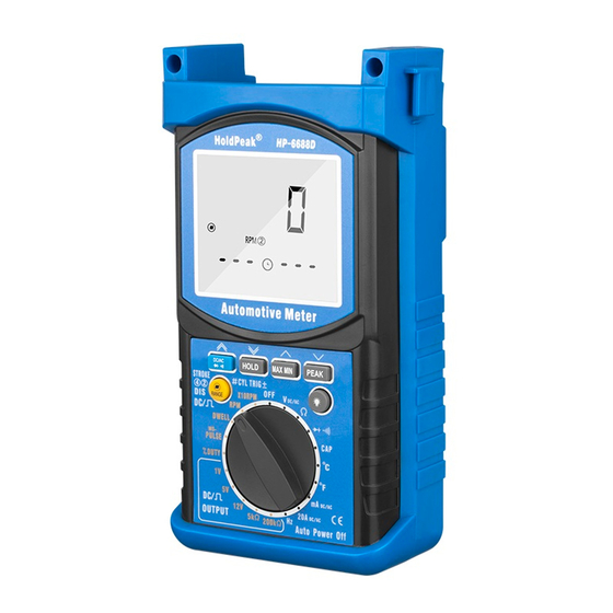
- Page 1 AUTOMOTIVE MULTIMETER INSTRUCTION MANUAL...
- Page 2 6688D Use current clamps to measure circuits exceeding 20A. 6000 DIGITAL AUTOMOTIVE ENGING ANALYZER MULTIMETER Danger OPERATION MANUAL Avoid electrical shock : do not touch the test leads ,tips or the circuit being tested. This instrument is a compact 、battery operated、handheld with safety protector 、...
- Page 3 Effect reading :>60RPM AC/DC 600mA 600mA AC/DC Accuracy:±(2.5%rdg+10dgt) AC/DC 20A 20A AC/DC Overload protection:250VDC or RMS AC Pulse width Duty Cycle(%) V/Ω/RPM 250V AC/DC Ranges :0.1ms-10.0ms Dwell angle Accuracy :±(2.5%+0.2ms) Overload protection:250VDC or RMS AC 20Amp measurement continuous for 30 seconds maximum. Ohm can not be measured if voltage is present ,ohms can be measured only in % Duty cycle a non-powered circuit .however ,the meter is protected to 250 volts.
-
Page 4: Audible Continuity
AC VOLTAGE TRUE RMS(Auto ranging) Sensitivity:1V Ranges:600mV,6V,60V,600V,750V Overload protection:250VDC or RMS AC Resolution:100uV Accuracy: : 400mV ,750V± (3.0%rdg+15dgt) at 50Hz to 100Hz CAPACITANCE(Auto ranging) ,4V,40V,400V, ± (1.5%rdg+15dgt) at 50Hz to 1kHz Ranges:9.999nF,99.99nF,999.9nF,9.999uF,99.99uF,999.9uF,9.999mF,99.99mF. input impedance:>10MΩ Resolution:1pF Overload protection: 1000VDC or 750VAC rms. Accuracy:±(3.0%rdg+20dgts) on 9.999nF range ±(2.5%rdg+10dgts) on 99.99nF to 9.999uF ranges ±(3.0%rdg+25dgts) on 99.99uF to999.9uF ranges... -
Page 5: Manual Ranging
Getting Started *if the range is too high ,the reading are less accurate. This chapter will help you get started. *if the range is too low ,the meter shows OL(over limit) It describes the basic functions of the meter. Push-button Functions Front Panel DC/AC BUTTON... - Page 6 new “max or min” occurs. Selection of a lower range will move the decimal point one place and 4.5.2. Press the MAX/MIN key and a blinking “MAX MIN” will appear. The meter increase the accuracy of the reading .An OL(Over limit) display means the will display the present reading, but will continue to update and store the max range is too low .select the next higher range.
- Page 7 *circuit open ,these is no “beep” and the display shows “OL” *Holding the probes with your hands may charge the capacitance in circuit and generate a false reading. 4. Diode check *Residual voltage charges on the capacitor. poor insulation resistance or poor IMPORTANT: Turn the power off to the test circult dielectric absorption may cause measurement errors.
- Page 8 Select the RPM range with the rotary switch. OR select the X10RPM range with rotary switch(60 to 12,000RPM). Multiply the Select the ms pulse range with the rotary switch. displayed reading times ten to get actual RPM. Insert: *Black lead in COM terminal. Insert the induction pick-up connecting *Red lead in V/ Ω/...
-
Page 9: Maintenance
Press the “AC/DC” function button to select AC or DC. Electrical System Diagnostics Insert: *Black lead in COM terminal. It is important to diagnose a vehicle electrical problem thoroughly and *Red lead in the 10A or mA terminal. efficiently . The series of tests that follow check primary areas that are responsible for the IMPORTANT: majority of the electrical problems found in an automobile . -
Page 10: No Load Test
NOTE: *Touch the positive(+)lead to the battery case around the positive (+) battery Leave the battery cable unhooked and proceed to the test post ,Do not touch the post . on the following page. A reading of more than 0.5V indicates excessive surface discharge . [3] Battery Test (Parasitic Load) Dirt ,moisture and corrosion are a cause of surface discharge .clean the battery This is for excessive parasitic drain on the battery. - Page 11 [4] Battery Test (Load) This tests the battery’s capacity to deliver sufficient cranking voltage. ·Set the rotary switch to Voltage. ·Connect the positive (+) lead to positive (+) battery terminal. ·Connect the negative (-) lead to negative (-) battery terminal. ·Disable the ignition;...
- Page 12 circuit or component creating resistance. seconds. The resistance decreases the amount of voltage available. The bulb will not The example shown has 2 connectors, 1 wire, 1 ground and 1 terminal to light or the motor will not turn if the voltage is too low. battery post.
- Page 13 ·Disable the ignition so the engine doesn’t start ; crank the engine for 2-3 [3] Battery Power to Starter Solenoid (+) seconds. This test checks battery source efficiency to the starter solenoid . The example shown has 4 connectors and 2 wire , and 2 solenoid ·Set the rotary switch to Voltage .
- Page 14 6-8Cyl, Under 300 CID 180-210 Amp, Maximum ·Start the engine and hold a 1500RPM. 6-8Cyl, Over 300 CID 250 Amp, Maximum A reading of 13.1-15.5 volts is an acceptable Charging rate. Charging System Tests [3] Alternator Amperage (A) Output, Battery [1] Battery (+) This test checks for alternator output voltage at the battery.
- Page 15 INSERT: the positive (B+) terminal on the coil. ·Black lead in COM terminal. Typical measurements are between 6000-30000’s Consult the manufacturer’s specifications for required resistance measurements. · Red lead in V/ Ω RPM [3] Secondary Ignition Wire Resistance Test (Ω) terminal.
- Page 16 specifications. This test checks for switching action in any hall Effect sensor (Ignition, RPM, Crankshaft, etc.) Rotor Test: ·Set the rotary switch to the Voltage (V) position. Connect the test probes to opposite ends of the rotor contacts . INSERT: ·Black lead in COM terminal.
- Page 17 diagnosis should precede any electrical system diagnostics. · Follow the published diagnostic Charts Exactly through every step to mark a Computerized vehicle control systems are made up of three basic component groups. These groups are: repair on computer component. Self-Diagnostic Computer Systems 1.
- Page 18 ·Duty cycle measured in percent of high or low time or dwell degrees an actuator is energized. For example; fuel injectors are activated by an (mixture control solenoid) electronic pulse from the engine control module. This pulse generates a magnetic field that pulls the injector nozzle valve open. The pulse ends and the injector nozzle is closed.
- Page 19 Watch the display; the Ohms reading should change as the signal arm on the Typical thermistor applications are: potentiometer is moved (signal sweep). ·Engine Coolant Temp. (ECT) Typical potentiometer applications are: ·Air Charge Temp. (ACT) ·Throttle position Sensor (TPS) ·Manifold Air Temp. (MAT) ·Exhaust Gas Recirculation valve position Sensor (EVP) ·Vane Air Temp.
- Page 20 ·Pulse width (fuel injector) measure the ON time (pulse). in the exhaust stream this voltage is used by the computer to change the ·Duty cycle (Mixture Control Solenoid) measure the percent of high (+) or air/fuel mixture. This test will check oxygen sensor signal output levels. low (-) time in a duty cycle.
- Page 21 4. Meter reading do not change. · “Hold”feature is still toggled ON. - 20 -...
Need help?
Do you have a question about the 6688D and is the answer not in the manual?
Questions and answers