Table of Contents
Advertisement
Quick Links
Advertisement
Table of Contents

Related Manuals for HoldPeak HP-760E


Summary of Contents for HoldPeak HP-760E
- Page 1 760E OPERATION MANUAL...
- Page 2 1. ATIONSAFETY INFORM SAFETY SYMBOLS Warning! Dangerous Voltage (Risk of electric shock). Caution! Refer to the user’s manual before using this Meter. Double Insulation (Protection Class Ⅲ). Alternating Current (AC). Direct Current (DC). Either DC or AC. Ground (maximum permitted voltage between terminal and ground).
- Page 3 and continuity test on a live power system. Do not apply voltage between the test terminals and test terminal to ground that exceed the maximum limit record in this manual. Exercise extreme caution when measuring live system with voltage greater than 60V DC or 30V AC. Change the battery when the “...
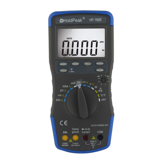
- Page 4 Figure1.terminal Rotary switch ■ Position of Function Rotary switch DC&AC Ampere current DC&AC milliampere current μA DC&AC microampere current 600A DC&AC Ampere current Transistor hFE test Duty cycle / Frequency DC&AC millivolts DC&AC voltage Capacitance Resistance, Diode & continuity Ω Temperature ℃/℉...
- Page 5 Figure2. Rotary switch Push button ■ Figure3. Push button 1.SELECT Press this button to select your measurement mode. ● 2.RANGE...
- Page 6 ● When the meter is powered on, the meter is in the auto range mode; press this button to select a specific measurement range. ● Press this push button more than 2 seconds the meter returns to auto range. 3.MAX/MIN ●...
- Page 7 reference value and displayed on the secondary display. Relative measurement has two modes. REL▲=measurement value-Reference value, the other is REL%=(REL▲/Reference value)×100% (press SELECT to select REL△ or REL% mode).. ● Set up reference value for your measurement. select your measurement function and your RANGE . ...
- Page 8 Low battery indication: Display " " sign. Data hold: Display “HOLD” sign. Relative measurement: Display “△” sign. Auto Power Off: Display “APO” sign. When measurement exceeds 15 minutes without switching mode and pressing key, the meter will switch to standby mode. Press any key or switch selector switch to exit standby mode.
- Page 9 : Express function New style patent of function direction light, easy use in dark place.
- Page 10 2.2 ELECTRICAL SPECIFICATIONS Accuracies are ± (% of reading + number in last digit )at 23 ± 5°C , ≤75% RH. 2.2.1 DC Voltage Range Accuracy Resolution 60mV ± ( 0.8% of rdg+10digits ) 0.01mV 600mV 0.1mV ± ( 0.5% of rdg+15 digits) 10mV 600V 100mV...
- Page 11 2.2.3 AC Voltage(True RMS/only 760D) Accuracy Range Resolution Sensitivity 50-500Hz 500-1KHz 1K-5KHz 5k-10KHz 10K-20KHz ± ( 1.2% of rdg+ ± ( 1.5% of rdg+ ± ( 2% of rdg+ ± ( 3.5% of rdg+ ± ( 4.5% of rdg+ 60mV 0.01Mv 50mV 10 digits )
- Page 12 2.2.4 DC Current Range Accuracy Resolution 600μA 0.1μA 6000μA 1μA ± ( 2.0% of rdg+10 digits ) 60mA 10μA 600mA 100μA ± ( 2.5% of rdg+10 digits) 10mA 600A ± ( 3.0% of rdg+10 digits) 100mA 20A up to 10 seconds; 600A range with AC/DC Current Clamp Adapter Overload protection: 0.8A/250V or 0.75A/250V, 20A/250V fuse 2.2.5 AC Current...
- Page 13 2.2.6 Resistance Range Accuracy Resolution 600Ω 0.1Ω 6kΩ 1Ω 60kΩ ± ( 1.2% of rdg+10 digits) 10Ω 600kΩ 100Ω 6MΩ 1kΩ 60MΩ ± ( 2.5% of rdg+15 digits ) 10kΩ Overload protection: 250V DC or AC rms 2.2.7 Capacitance Range Accuracy Resolution 40nF...
- Page 14 Overload protection: 250V DC or AC rms 2.2.9 Frequency Range Accuracy Resolution 10Hz 0.01Hz 100Hz 0.1Hz 1000Hz 10kHz ± ( 0.5% of rdg+5 digits) 10Hz 100kHz 100Hz 1000kHz 1kHz 10MHz 10kHz Sensitivity: Range of input voltage:1.5V~10V, If input voltage over range, need adjust It can not display bar graph on frequency range Overload protection: 250V DC or AC rms...
- Page 15 Overload protection: 250V DC or AC rms 2.2.12 hFE test Ib = 10μA Vce = 2V Approx. Test range : 0~1000. 3. OPERATION 3.1 DC and AC Voltage Measurement 1) Set the selector switch to desired “mV ” or “V ” position. 2) Connect the black test lead to "COM"...
- Page 16 2) Connect the black banana plug of the AC/DC Special Current Clamp Adapter to "COM" socket and the red banana plug to the "µAmA" socket. 3) Press “SELECT” key to choose “DC” or “AC” measurement. 4) When perform DC current measurement, always rotate or push the DCA zero adjuster on the Clamp Adapter until the multimeter reads zero.
- Page 17 Note: a) Before testing, discharge the capacitor by shorting its leads together. Use caution in handing capacitors because they may have a charge on them of considerable power before discharging. b) Before testing, press “REL△” key to eliminate the zero error. c) When testing 4000µF capacitor, note that there will be approx.
- Page 18 1) Set the selector switch to desired “℃/℉” position. 2) Connect the black banana plug of the sensor to "COM" socket and red banana plug to the "VΩHz" socket. 3) Press “SELECT” key to choose ℃ or ℉ measurement. 4) Put the sensor probe into the temperature field under measurement.
-
Page 19: Battery Replacement
measurement. It can not display bar graph on Relative measurement mode. 3.13 Auto/Manual range The auto range mode is a convenient function, but it might be faster to manually set the range when you measure values that you know to be within a certain range. To select manual range, repeatedly press “RANGE”... - Page 20 5. Fuse replacement 1) This meter is provided with a 0.8A/250V fuse to protect the current measuring circuits which measure up to 600mA, with a 10A/250V fuse to protect the 10A range. 2) Ensure the instrument is not connected to any external circuit, set the selector switch to “OFF”...
Need help?
Do you have a question about the HP-760E and is the answer not in the manual?
Questions and answers