Table of Contents
Advertisement
Quick Links
Download this manual
See also:
User Manual
Advertisement
Table of Contents

Subscribe to Our Youtube Channel
Related Manuals for Neousys Technology Nuvo-6108GC Series


Summary of Contents for Neousys Technology Nuvo-6108GC Series
- Page 1 Neousys Technology Inc. Nuvo-6108GC Series User Manual Revision 1.0...
-
Page 2: Legal Information
For questions in regards to hardware/ software compatibility, customers should contact Neousys Technology Inc. sales representative or technical support. To the extent permitted by applicable laws, Neousys Technology Inc. shall NOT be responsible for any interoperability or compatibility issues that may arise when (1) products, software, or options not certified and supported;... -
Page 3: Contact Information
Neousys Technology Inc. (Taipei, Taiwan) 15F, No.868-3, Zhongzheng Rd., Zhonghe Dist., New Taipei City, 23586, Taiwan Tel: +886-2-2223-6182 Fax: +886-2-2223-6183 Email, Website Americas Neousys Technology America Inc. 3384 Commercial Avenue, Northbrook, IL 60062, USA (Illinois, USA) Tel: +1-847-656-3298 Email, Website China Neousys Technology (China) Ltd. -
Page 4: Copyright Notice
This manual is intended to be used as an informative guide only and is subject to change without prior notice. It does not represent commitment from Neousys Technology Inc. Neousys Technology Inc. shall not be liable for any direct, indirect, special, incidental, or consequential damages arising from the use of the product or documentation, nor for any infringement on third party rights. -
Page 5: Safety Precautions
Safety Precautions Safety Precautions Read these instructions carefully before you install, operate, or transport the system. Install the system or DIN rail associated with, at a sturdy location Install the power socket outlet near the system where it is easily accessible ... -
Page 6: Service And Maintenance
ESD Precautions Service and Maintenance ONLY qualified personnel should service the system Shutdown the system, disconnect the power cord and all other connections before servicing the system When replacing/ installing additional components (expansion card, memory module, etc.), insert them as gently as possible while assuring proper connector engagement ESD Precautions ... -
Page 7: Table Of Contents
Table of Contents Table of Contents Legal Information ......................2 Contact Information ......................3 Declaration of Conformity ....................3 Copyright Notice ....................... 4 Safety Precautions ......................5 Service and Maintenance ....................6 ESD Precautions ....................... 6 Table of Contents ......................7 About This Manual ...................... -
Page 8: About This Manual
Nuvo-6108GC About This Manual This guide introduces Neousys Nuvo-6108GC system. An industrial grade GPU computer integrating high-end NVIDIA® GeForce® with Intel® Xeon® E3 v5 or 6th Gen Core™ processors. The guide also demonstrates the system’s basic installation procdures. Revision History Version Date Description... -
Page 9: Introduction
Nuvo-6180GC Introduction The Neousys Nuvo-6108GC is the world’s first industrial-grade GPU computer integrating NVIDIA® GeForce® GTX 1070, 1080 or TITAN X and an Intel Xeon processor. The perfect replace for massive rackmount IPC systems, Nuvo-6108GC is powered Gen Core™ processor with C236 chipset, supports up by Intel®... -
Page 10: Product Specifications
Nuvo-6108GC Product Specifications System Core Supports Intel® Xeon® E5 v3 and 6th-Gen Core™ LGA1151 CPU - Intel® Xeon® Processor E3-1275 v5 (8M Cache, 3.6/4.0 GHz)* - Intel® Xeon® Processor E3-1268L v5 (8M Cache, 2.4/3.4 GHz) Processor - Intel® Core™ i7-6700 (8M Cache, 3.4/4.0 GHz)* - Intel®... -
Page 11: Dimension
Nuvo-6180GC Dimension 1.2.1 I/O Panel View 1.2.2 Side View... -
Page 12: I/O Panel View With Damping Bracket Installed
Nuvo-6108GC 1.2.3 I/O Panel View with Damping Bracket Installed 1.2.4 Bottom View with Damping Bracket Installed... -
Page 13: System Overview
Upon receiving and unpacking your Nuvo-6108GC, please check immediately if the package contains all the items listed in the following table. If any item(s) are missing or damaged, please contact your local dealer or Neousys Technology. Nuvo-6108GC Packing List System... -
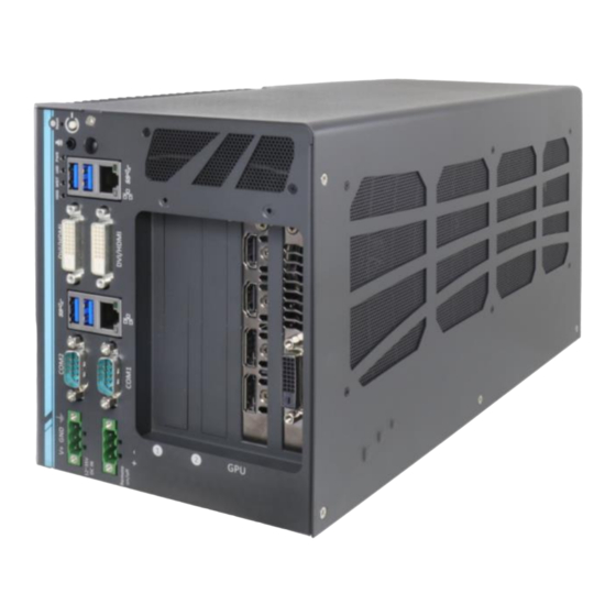
Page 14: External I/O
Nuvo-6108GC External I/O The Nuvo-6108GC I/O panel features dual gigabit Ethernet, four USB3.0, dual DVI ports (off motherboard chipset), dual serial ports and DisplayPort/ HDMI/ DVI on the dual-slot graphics card. Item Description Reset button Use this button to manual restart the system. Power button Use this button to turn on or force shutdown the system. - Page 15 Nuvo-6180GC offers fast network access. DVI-D output supports resolution up to 1920x1200@60Hz DVI-D port and is compatible with other digital connections via an adapter. USB 3.0 port supports up to 5 Gbit/s data transfer USB 3.0 port bandwidth. Gigabit Ethernet Implemented via Intel I210-LM, the Gigabit Ethernet port port offers fast network access.
-
Page 16: Reset Button
Nuvo-6108GC 2.2.1 Reset Button The reset button can be used to manually reset the system in case of abnormal condition. To avoid unexpected operation, the reset button is hidden behind the front panel. You need to use a pin-like object to push the reset button. -
Page 17: Power Button
Nuvo-6180GC 2.2.2 Power Button The power button is a non-latched switch for ATX mode on/off operation. Press to turn on the system, PWR LED should light up and to turn off, you can either issue a shutdown command in the OS, or just press the power button. In case of system halts, you can press and hold the power button for 5 seconds to force-shutdown the system. -
Page 18: Speaker-Out 3.5Mm Jack
Nuvo-6108GC 2.2.3 Speaker-out 3.5mm Jack The system’s audio output is provided via Intel® High Definition Audio (built-in in H110 PCH) and Realtek ALC262 codec. There is an audio jack available on the I/O panel for headphone/ speaker output. To utilize the audio function in Windows, you need to install corresponding drivers for both Intel®... -
Page 19: Led Indicators
Nuvo-6180GC 2.2.4 LED Indicators There are four LED indicators on the I/O panel: PWR, UID, WDT and HDD. The descriptions of these three LED are listed in the following table. Indicator Color Description Green Power indictor, lighted-up when system is on. Green Reserved for future usage. -
Page 20: Usb 3.0 Port
Nuvo-6108GC 2.2.5 USB 3.0 Port The system offers four USB 3.0 (SuperSpeed USB) ports on its I/O panel. They are implemented by native xHCI (eXtensible Host Controller Interface) controller in H110 chipset and are compatible with USB 3.0, USB 2.0, USB 1.1 and USB 1.0 devices. Legacy USB support is also provided so you can use USB keyboard/mouse in DOS environment. -
Page 21: Gigabit Ethernet
Nuvo-6180GC 2.2.6 Gigabit Ethernet The system offers 2 GbE ports on its I/O panel. The GbE ports are marked in blue/ ® ® and are implemented with Intel I219-LM/ Intel I210-IT controllers, respectively. Each port has one dedicated PCI Express link for maximum performance. When an Ethernet connection is established, the LED indicators on the RJ45 connector represents the following connection statuses: Active/Link LED... -
Page 22: Dvi Connector
Nuvo-6108GC 2.2.7 DVI Connector The system has two DVI connectors on its I/O panel to support dual independent display outputs. DVI transmits graphics data in digital format and therefore can deliver better image quality at high resolutions. The DVI connector can output DVI or other digital signals via an adaptor or dedicated cable up to 1920 x 1200 resolution. -
Page 23: Com Port And Pin Definition
Nuvo-6180GC 2.2.8 COM Port and Pin Definition The system provides totally five COM ports for communicating with external devices. These COM ports are implemented using industrial-grade ITE8786 Super IO chip (-40 to 85°C) and provide up to 115200 bps baud rate. COM1 and COM2 are software-selectable RS-232/422/485 ports. - Page 24 Nuvo-6108GC COM Port Pin Definition COM1 & COM2 RS-485 Mode Pin# RS-232 Mode RS-422 Mode (Two-wire 485) 422 RXD- 422 RXD+ 422 TXD+ 485 TXD+/RXD+ 422 TXD- 485 TXD-/RXD-...
-
Page 25: 3-Pin Terminal Block For Dc Input
Nuvo-6180GC 2.2.9 3-Pin Terminal Block for DC Input The system allows DC power input from 8 to 35V via a 3-pin pluggable terminal block, which is ideal for field usage where DC power is provided. The screw clamping mechanism of the terminal block offers utmost reliability when wiring DC power. Symbol Description Chassis ground (connect to the earth ground) -
Page 26: 2.2.10 3-Pin Remote On/ Off
Nuvo-6108GC 2.2.10 3-Pin Remote On/ Off The “Remote On/ Off” 3-pin connection allows for external switch extension. It is useful when the system is placed in a cabinet or a not easily accessed location. - Page 27 Nuvo-6180GC PCIe x8 Slot...
-
Page 28: Operating System Support
Nuvo-6108GC Operating System Support The system supports most operating system developed for Intel® x86 architecture. The following list contains the operating systems which have been tested in Neousys Technology Inc. Microsoft Windows 8/8.1 32-bit Microsoft Windows 8/8.1 64-bit ... - Page 29 In this section, we’ll illustrate how to use the function library provided by Neousys to program the WDT functions. Currently, WDT driver library supports Windows 7/ 8.1/ 10 32-bit and 64-bit versions. For other OS support, please contact Neousys Technology for further information.
-
Page 30: Wdt And Dio Library Installation
Nuvo-6108GC WDT and DIO Library Installation To setup WDT & DIO Library, please follow instructions below. 1. Execute WDT_DIO_Setup.2.2.4.exe. and the following dialog appears. 2. Click “Next >” and specify the directory of installing related files. The default directory is C:\Neousys\WDT_DIO. - Page 31 Nuvo-6180GC 3. Once the installation has finished, a dialog will appear to prompt you to reboot the system. The WDT & DIO library will take effect after the system has rebooted. 4. When programming your WDT or DIO program, the related files are located in Header File: \Include Library File:...
-
Page 32: Wdt Functions
Nuvo-6108GC WDT Functions 4.2.1 InitWDT BOOL InitWDT(void); Syntax Description: Initialize the WDT function. You should always invoke InitWDT() before set or start watchdog timer. Parameter None Return Value TRUE: Successfully initialized FALSE: Failed to initialize Usage BOOL bRet = InitWDT() 4.2.2 SetWDT BOOL SetWDT(WORD tick, BYTE unit);... -
Page 33: Startwdt
Nuvo-6180GC 4.2.3 StartWDT BOOL StartWDT(void); Syntax Description Starts WDT countdown. Once started, the WDT LED indicator will begin blinking. If ResetWDT() or StopWDT is not invoked before WDT countdowns to 0, the WDT expires and the system resets. Parameter None Return Value f the timeout value is given in correct format (WDT started), this function returns TRUE, otherwise FALSE...
Need help?
Do you have a question about the Nuvo-6108GC Series and is the answer not in the manual?
Questions and answers