
Related Manuals for Greenwood Fusion HRV2HT


Summary of Contents for Greenwood Fusion HRV2HT
- Page 1 Fusion HRV2HT Mechanical Ventilation with Heat Recovery Installation Instructions Commissioning Data: To be completed by the Commissioning Engineer. Refer to User/Homeowner Guide also supplied.
-
Page 2: Table Of Contents
Contents General Description / Page 2 Physical Specification Installation Instructions Page 3 General Preparation Page 3 Positioning Page 3 Mounting Page 6 Condensate Drain Page 9 Ducting Guidelines Page 9 Electrical Page 10 Wiring Diagrams Page 11 Connecting to the BMS Page 12 On Site Commissioning Page 14... -
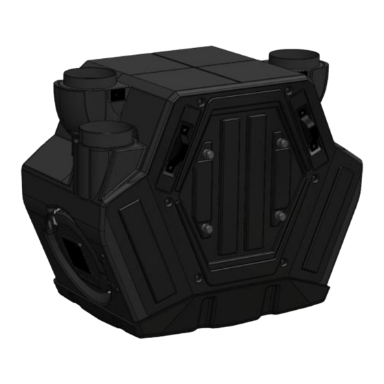
Page 3: Physical Specification
Physical Specification Front View Side View Installation Instructions General Preparation 2.1.1 The HRV2HT unit is supplied with 4 x 125mm spigots. Ø 125mm ducting with connectors can be used (see ancillary section page 2) to provide performance levels 2.1.2 required for compliance with Building Regulations. 2.1.3 Installation of the HRV2HT should be in accordance with the current editions of Building Regulations and BS7671: IEE Wiring Regulations. - Page 4 2.2.5 Configuration Symbols Exhaust Air Intake Air Supply Air Extract Air – Port to exhaust stale air to outside Exhaust Air – Port to intake fresh air from outside Intake Air – Port to supply fresh air to dry rooms Supply Air –...
- Page 5 2.2.7 Left Hand Configuration The handing of the unit can be changed by following the 3 steps as shown below (See Figure 2), and does not require any internal changes. Remove both filters from the unit. Rotate unit through 180 degrees. Reinsert both filters into the unit.
-
Page 6: Mounting
Mounting (Vertical Installation Only) 2.3.1 The HRV2HT unit is supplied with one wall fixing bracket. The bracket has six fixing points available; four of these are slotted, and located in each corner. Minimum acceptable number of fixing points for mounting is four. - Page 7 2.3.5 Access for Maintenance Footprint of HRV2HT (top view) 150mm 500mm Figure 9 2.3.6 Controller Mounting The GRF1 and GRF2 controllers can be mounted to the wall, however only the GRF1 controller can be mounted to the HRV2HT unit. The controller is supplied with one back box, one fixing plate and one screw and raw plug set.
- Page 8 2.3.8 Unit Mounting for GRF1 only (See Figure 11 & 12) Remove the ‘access for controls pairing’ panel (See Figure 11) located on the flying lead side of the HRV2HT revealing the docking connector. Using the original two screws, mount the fixing plate (See Figure 12) to the unit.
-
Page 9: Condensate Drain
Condensate Drain It is important that any condensate MUST be drained away. The unit is provided with a condensate drain 2.4.1 located centrally at the base of the unit underneath (See Figures 15 & 16). The drain plug allows a condensate drain hose (22mm diameter) to be push connected and secured to the wall. -
Page 10: Electrical
A double-pole switch having a minimum contact separation of 3.0mm must be used to provide isolation for the unit. 2.6.7 The recommended switches for use with this product are the Greenwood Airvac; – LCD Radio Frequency controller (for commissioning & advanced user controls) GRF1 –... -
Page 11: Wiring Diagrams
Wiring Diagrams Page | 11... -
Page 12: Connecting To The Bms
Connecting to the Building Management System (BMS) The HRV2HT can be connected and controlled by a Building Management System that can provide a 0 – 2.8.1 10V output. Control and operation of the commissioned speeds can be applied as follows; Voltage Speed Control 0V –... - Page 13 2.8.5 Using suitably sized cabling, route the cable towards the BMS connector. With a sharp object pierce through the thinned layer of membrane around the front of the BMS Gland dust cover and feed cable through leaving adequate length to wire into connector pins. Now wire into the connector pins.
-
Page 14: On Site Commissioning
On Site Commissioning (using the GRF1) 2.9.1 This section covers set up, configuration of the unit for installation and altering pre-set factory settings. For instructions on how to operate the GRF1 LCD display user menu, maintenance options and indicator warning information, please refer to the User / Homeowner Guide. Once the wiring connections have been checked, switch the mains supply on and check that the system is operating correctly. - Page 15 2.9.4 GRF2 (Option) At the start of pairing please ensure the GRF2 controller does not have batteries inserted. Remove the ‘access for controls pairing’ panel (See Figure 23), located on the flying lead side, to reveal the registration button and LED (See Figure 24).
- Page 16 2.9.6 Valve Set-up Switch the unit to the highest operating position. Close external windows and doors. With the system operating in boost mode, proceed to open the extract valves to their maximum. Measure the total air volume at the extract valves. Regulate the extract valves to the required flow per room.
- Page 17 2.9.9 General Controls The four buttons on the controller have different functions dependent on which screen or menu you are in. Enter/Exit/Confirm Navigation/Adjustment Speed//Exit/Cancel Button Functionality is Menu/Screen Dependent Details of the respective functions of these are shown within- Normal Operation Display (See User / Homeowner Guide Section 3.1.3) User Menu (See User / Homeowner Guide Section 3.1.7)
- Page 18 Below is the schematic of how to navigate around the Commissioning Menu. Note: For specific adjustment details, please refer to respective function shown on Page 20 Page | 18...
- Page 19 2.9.11 Example: Setting Intake/Supply Trickle Speed to 40% Sequence Instruction Display Image Description Enter commissioning Hold [ menu password screen Enter first password Press [ character Enter second password Press [ character Enter third password Press [ character Confirm password and enter commissioning Press [ menu, Clock icon shown...
- Page 20 Boost Speed speed setting Exhaust/Extract Exhaust/Extract boost 40 – 99% Boost Speed speed setting Temperature at which frost protection Greenwood -2 – 0 is activated WinterSMART (See Section 5 of the User/Homeowner Guide) Temperature at which summer slowdown Greenwood 18 – 35...
- Page 21 2.9.13 De-registering the GRF1 or GRF2 controllers In the event that either the GRF1 or GRF2 controllers need to be de-registered from the HRV2HT, the following steps need to be performed: 2.9.14 GRF1 Whilst the HRV2HT unit is still running remove one of the batteries from the GRF1. Press and hold [ ] on the GRF1 controller whilst reinserting the removed battery (See Section...
- Page 22 2.9.16 Performance Graph - Airflow Characteristics for HRV2HT Trickle Speed Factory Setting Factory Set Boost Speed Boost Speed Factory Setting Factory Set Trickle Speed Airflow l/s Figure 30 Page | 22...
-
Page 23: Guarantee
All information is believed correct at time of going to press. E&OE. All goods are sold according to Greenwood Air Management Ltd’s Standard Conditions of Sale which are available on request. All dimensions referred to are in millimetres unless otherwise stated. - Page 24 Greenwood Air Management Ltd Greenwood House, Brookside Avenue, Rustington, West Sussex, BN16 3LF. Main Line Tel: +44 (0) 1903 771021 Technical Services: +44 (0) 1903 777135 Main Line Fax: +44 (0) 1903 782398 Web: www.greenwood.co.uk Email: info@greenwood.co.uk Page | 24...
Need help?
Do you have a question about the Fusion HRV2HT and is the answer not in the manual?
Questions and answers