
Related Manuals for Canon Cassette Feeding Unit-AP1


Summary of Contents for Canon Cassette Feeding Unit-AP1
- Page 1 Cassette Feeding Unit-AP1 SERVICE MANUAL October 20, 2016 Rev. 1 CANON Cassette Feeding Unit-AP1 Rev. 1 PRINTED IN U.S.A. COPYRIGHT © 2016 CANON INC.
- Page 2 When changes occur in applicable products or in the contents of this manual, Canon will release technical information as the need arises. In the event of major changes in the contents of this manual over a long or short period, Canon will issue a new edition of this manual.
- Page 3 Introduction Symbols Explanation Symbols Explanation Disconnect the connector. Connect the power cable. Connect the connector. Disconnect the power cable. Remove the cable/wire from the Turn on the power. cable guide or wire saddle. Install the cable/wire to the cable Turn off the power. guide or wire saddle.
-
Page 4: Table Of Contents
Contents Contents Safety Precautions....................1 Notes Before it Works Serving......................2 Points to Note at Cleaning........................2 Notes on Assembly/Disassembly......................2 1. Product Overview.....................3 Overview............................. 4 Specifications............................4 Names of Parts............................. 4 2. Technology....................... 6 Basic Configuration..........................7 Parts Configuration..........................7 Controls............................. 10 Lifter control............................10 Cassette Pickup Control........................ - Page 5 Contents Installation Outline Drawing......................... 32 Check Items when Turning OFF the Main Power...................32 Unpacking............................32 Checking the Contents........................35 Installation Procedure........................36 Setting the Cassette.......................... 42 APPENDICES......................43 General Circuit Diagram........................44...
-
Page 6: Safety Precautions
Safety Precautions Notes Before it Works Serving....2 Points to Note at Cleaning....2 Notes on Assembly/Disassembly..2... -
Page 7: Notes Before It Works Serving
Safety Precautions Notes Before it Works Serving • At servicing, be sure to turn OFF the power source according to the specified steps and disconnect the power plug. • Be sure to disconnect the power plug on a regular basis and remove dust and dirt accumulated around the outlet with dry cloth. -
Page 8: Product Overview
Product Overview Overview..........4... -
Page 9: Overview
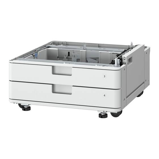
1. Product Overview Overview Specifications Item Specification Pickup method Separation retard method Paper stack capacity 550 sheets (80g/m 640 sheets (64g/m Cassette Paper feed reference Center reference Paper Type Thin (52 to 63 g/m ), Plain (64 to 105 g/m Color, Recycled (64 to 105 g/m ), Transparency, Heavy (106 to 220 g/m Pre-Punched, and Bond... - Page 10 1. Product Overview Parts Name Cassette Cover (Rear) Cassette Connector Cover Cassette Cover (Right Rear) Cassette Right Door Assembly Cassette Right Cover (Lower) Cassette Cover (Right Front)
-
Page 11: Technology
Technology Basic Configuration....... 7 Controls..........10... -
Page 12: Basic Configuration
2. Technology Basic Configuration Parts Configuration M103 M102 M101 Parts Name Parts Name Cassette 3 Pickup Roller M101 Cassette 3,4 Pickup Motor Cassette 3 Feed Roller M102 Cassette 3,4 Lifter Motor Cassette 3 Vertical Path Roller M103 Cassette 3,4 Feed Motor Cassette 3 Separation Roller Cassette 4 Vertical Path Roller Cassette 4 Separation Roller... - Page 13 2. Technology SW102/SW104 SW103/SW105 Parts Name Parts Name Trailing Edge Guide Plate SW102/SW104 Cassette Size Switch A Link Arm SW103/SW105 Cassette Size Switch B Side Guide Plate Size Detection Plate...
- Page 14 2. Technology PS104/PS105 PS102/PS103 PS107/PS108 PS109/PS110 Parts Name Parts Name Lifter Gear PS104/ PS105 Cassette Lifter Sensor Paper Detection Lever PS102/ PS103 Cassette Paper Sensor Middle Plate PS107/ PS108 Cassette Paper Level Sensor A PS109/ PS110 Cassette Paper Level Sensor B...
-
Page 15: Controls
2. Technology Controls Lifter control Paper inside a cassette is lifted up by the Lifting Plate. The Middle Plate is lifted by the rotation of the Cassette 3,4 Lifter Motor (M102). When the paper surface reaches the position of the Pickup Roller, the Cassette Lifter Sensors(PS104/PS105) are turned ON to detect that the paper has reached the pickup position. - Page 16 2. Technology Result of automatic Paper Size Group for Auto Recog. in Drawer*1 size detection All Sizes A/B-Size Inch Size A/K Size EXEC Depends on the setting*3 No corresponding size EXEC No corresponding size No corresponding size Depends on the setting*3 No corresponding size EXEC K16R K16R...
-
Page 17: Paper Level/ Presence Detection
2. Technology NOTE: • Selection between A5R and STMTR Settings/ Registration > Preferences > Paper Settings > A5R/ STMTR Paper Selection Setting value - Cassette 3: A5R, STMTR Cassette 4: A5R, STMTR • Service Mode (Lv.1) COPIER > OPTION > CST > CSTX-P1 (where 'X' is the cassette number (2 to 4)) Setting Value - 0: A5R, 1: STMTR Paper level/ presence detection The level and presence of paper in the cassette are detected by four sensors. - Page 18 2. Technology Cassette Paper Paper Sensor Paper Cassette Lifter Sensor Cassette Paper Level Sensor B Cassette Paper Level Sensor A...
-
Page 19: Periodical Service
Periodical Service List of Periodical Service Works..15... -
Page 20: List Of Periodical Service Works
3. Periodical Service List of Periodical Service Works Periodically replacement parts There is no periodically replaced part with this machine. Consumables No durable parts is set for this machine. -
Page 21: Disassembly/Assembly
Disassembly/ Assembly Parts List..........17 Parts Replacement......18... -
Page 22: Parts List
4. Disassembly/Assembly Parts List PS104 PS101 SW102 PS102 SW103 PS106 PS105 PS103 SW105 SW104 H02_02 SW101 PS108 PS107 M101 M103 M102 PS110 PS109 UN11 Name PS101 Cassette 3 Vertical Path Sensor PS102 Cassette 3 Paper Sensor PS103 Cassette 4 Paper Sensor PS104 Cassette 3 Lifter Sensor PS105... -
Page 23: Parts Replacement
4. Disassembly/Assembly Parts Replacement Remove from the host machine ■ Procedure 1. Remove the Hiding Cover. 2. Open the Right Door(Lower). 3. Remove the Cassette. - Page 24 4. Disassembly/Assembly 4. Remove the Cassette Connector Cover (Lower). • 2 Claws...
- Page 25 4. Disassembly/Assembly 5. Remove the Cassette Connector Cover (Upper). • 2 Claws 6. Remove the connectors. • 2 Connectors 7. Remove the 3 Screws fixing the host machine and the cassette pedestal.
-
Page 26: Removing The Cassette 3/4 Pickup/Feed/Separation Roller
4. Disassembly/Assembly 8. Remove the host machine. Removing the Cassette 3/4 Pickup/Feed/Separation Roller ■ Preparation 1. Open the Right Door(Lower). 2. Remove all Cassettes. ■ Procedure NOTE: The removing procedure for Cassette 3 is written in the procedure. For Cassette 4, proceed the same procedure as Cassette 3. 1. -
Page 27: Removing The Cassette 3 Pickup Unit
4. Disassembly/Assembly 2. Pull the Pickup Roller [2]/Feed Roller [3]/Separation Roller [4] while holding down the claw [1]. • 3 Claws [1] NOTE: When the consumable parts are replaced, be sure to clear the parts counter in the service mode. •... - Page 28 4. Disassembly/Assembly 11. Remove the Cassette Cover(Right Rear). ■ Procedure NOTE: The removing procedure for Cassette 3 Pickup Unit is written in the procedure. For Cassette 4, proceed the same procedure as Cassette 3 Pickup Unit. 1. Release the connector [1] on the Harness Guide. •...
- Page 29 4. Disassembly/Assembly 2. Remove the Cassette Right Door Open/Close Detection Switch [1]. • 1 Screw [2] • 2 Hooks [3] 3. Remove the Pickup Unit [1]. • 4 Screws [2]...
-
Page 30: Adjustment
Adjustment Image position adjustment....26... -
Page 31: Image Position Adjustment
5. Adjustment Image position adjustment CAUTION: Adjusting the 1st side also changes the margin on the 2nd side. If the difference between the 1st and the 2nd sides is +/- 0.5 mm or less, do not adjust the 2nd side. •... - Page 32 5. Adjustment 3. Loosen the Fixation screw. 4. Move the Adjustment Plate left or right according to the scale value checked in step 2. (As the Adjustment Plate is moved toward the left on the machine by 1 tooth, the left edge margin is increased by 0.5mm.) Scale Teeth 5.
-
Page 33: Software Adjustment
5. Adjustment 6. Pull out the next upper cassette, and check that the Adjustment Plate is correctly pushed against the frame. CAUTION: If the Adjustment Plate is not correctly pushed against the frame, image cannot be correctly adjusted. When checking Cassette 3, the Between-cassette Cover needs to be removed. 7. - Page 34 5. Adjustment 3. If the service mode has been changed, write the new adjustment value on the service label. Standard value • Leading edge : 4.0 + 1.5/ -1.0 mm (front side, back side) • Left edge : 2.5+/ -1.5 mm (front side) / 2.5+/ -2.0 mm (back side) Feed direction COPIER>ADJUST>FEED-ADJ COPIER>ADJUST>FEED-ADJ...
-
Page 35: Installation
Installation How to Check the Installation Procedure........31 Pre-checks.......... 32 Installation Procedure......36 Setting the Cassette......42... -
Page 36: How To Check The Installation Procedure
6. Installation How to Check the Installation Procedure Symbols The frequently-performed operations are described with symbols in this procedure. Screw Tighten Loosen Packaged Item Unused Parts Remove Install Harness (Common for Guides Connector Power Cord and Clamps) Connect Disconnect Connect Disconnect Remove Install... -
Page 37: Pre-Checks
6. Installation 1. Turn OFF the main power switch of the host Pre-checks machine. 2. Be sure that Control Panel Display and Main Power Product Name Lamp are both turned OFF, and then disconnect the power plug. Safety regulations require the product's name to be registered. - Page 38 6. Installation NOTE: Remove all the attached tapes and packaging materials. NOTE: Take out the contents. NOTE: Perform steps 3 to 5 in each cassette.
- Page 39 6. Installation CAUTION: NOTE: Remove all the tapes and fixation materials from the Do not operate the Trail Edge Guide Plate/Side Guide cassette 3 and cassette 4. Plate without pulling out the cassette. Otherwise, it may be damaged. Trail Edge Guide Plate Side Guide Plate NOTE: Remove the tapes from the exterior of this equipment, and...
-
Page 40: Checking The Contents
6. Installation Checking the Contents... -
Page 41: Installation Procedure
6. Installation Installation Procedure NOTE: If there is a Handle Cover, remove it. NOTE: If there is a Right Cover (Lower), remove it. NOTE: The removed cover will be used in step 13. NOTE: The removed cover will be used in step 14. CAUTION: If mounting the host machine without opening the Right Cover (Lower), the cover may get damage. - Page 42 6. Installation NOTE: Holding the handles, mount the host machine by aligning the corners (right and left) of the front side of the host machine with the corners (right and left) of the front side of the Cassette Pedestal. CAUTION: Connecting the host machine and this equipment Do not mount the host machine with the cables of this equipment inside.
- Page 43 6. Installation NOTE: Use the cover removed in step 6. NOTE: The removed cover will be used in step 8.
- Page 44 6. Installation NOTE: Securely tighten the coin screw with a stubby screwdriver or a coin. CAUTION: • When tightening the coin screws, pay attention to plates and parts around the screws. • When tightening a screw on the rear side, be careful not to drop it.
- Page 45 6. Installation NOTE: NOTE: Install the Cassette 1 with the rails extended. If you have removed the cover , use the cover removed in step 1. Or, use the part included in the package of the host machine. NOTE: If you have removed the cover , use the cover removed in step 3.
- Page 46 6. Installation Insert the power plug into the power plug outlet, and turn ON the main power switch. NOTE: • Move the host machine to the installation position, and rotate the 3 adjusters clockwise by hand to secure the host machine in place. •...
-
Page 47: Setting The Cassette
6. Installation Setting the Cassette NOTE: • Be sure to check with the user before affixing the Paper Size Label. Be sure to affix it at the recommended position. NOTE: • Affix the Cassette Size Label matching to the loaded •... -
Page 48: Appendices
APPENDICES General Circuit Diagram......44... -
Page 49: General Circuit Diagram
General Circuit Diagram General Circuit Diagram Cassette Pedestal From P.3 J1097L 13 12 11 10 9 J601 UN11 Cassette Pedistal Driver PCB J604 J606 J603 J602 J605 J610 9 10 12 13 14 15 16 17 18 19 20 J1252 J1196 8-292112-4 J1187D...
Need help?
Do you have a question about the Cassette Feeding Unit-AP1 and is the answer not in the manual?
Questions and answers