Compaq ProLiant DL580 Setup And Installation Manual
Hide thumbs
Also See for ProLiant DL580:
- Maintenance and service manual (193 pages) ,
- Specification (32 pages) ,
- Quick specification (28 pages)

Related Manuals for Compaq ProLiant DL580


Summary of Contents for Compaq ProLiant DL580
- Page 1 ProLiant DL580 Server Setup and Installation Guide Third Edition (May 2001) Part Number 159213-003 Compaq Computer Corporation...
- Page 2 Compaq, the Compaq logo, Compaq Insight Manager, ProLiant, ROMPaq, and SmartStart Registered in U.S. Patent and Trademark Office. CarePaq is a trademark of Compaq Information Technologies Group, L.P. in the United States and other countries. Microsoft, MS-DOS, Windows, and Windows NT are trademarks of Microsoft Corporation in the United States and other countries.
-
Page 3: Table Of Contents
Contents About This Guide Text Conventions......................x Symbols in Text......................x Symbols on Equipment....................xi Rack Stability ......................xii Getting Help ......................xii Compaq Technical Support ................xii Compaq Website....................xiii Compaq Authorized Reseller................xiii Chapter 1 Server Features System Features ....................... 1-2 Processors ......................1-3 Expansion Slots .................... - Page 4 Compaq ProLiant DL580 Server Setup and Installation Guide Server Features continued Server Management and Configuration Tools ............1-13 Compaq SmartStart..................1-13 Compaq Integrated Management Log............. 1-14 Compaq Insight Manager................1-14 Compaq Survey Utility ................... 1-15 Drive Fault Tolerance ..................1-16 Automatic Server Recovery-2 (ASR-2) ............
- Page 5 External SCSI Connector..................3-2 Array Configuration....................3-2 Chapter 4 Installing the Server Installation Choices ....................4-1 Compaq Optional Installation Service.............. 4-1 Using the Procedures in this Chapter..............4-1 Rack Warnings and Precautions ................4-3 Server Warnings and Precautions ................4-3 Installation Overview....................4-5 Preparing the Server for Installation ................
- Page 6 Compaq ProLiant DL580 Server Setup and Installation Guide Chapter 6 PCI Hot Plug Technology PCI Hot Plug Capability ..................6-2 PCI Hot Plug Technology ..................6-3 PCI Hot Plug System ..................6-3 PCI Hot Plug Application ................. 6-3 PCI Hot Plug Operations .................. 6-3 PCI Hot Plug Button ..................
- Page 7 Contents vii Appendix A Regulatory Compliance Notices Regulatory Compliance Identification Numbers .............A-1 Federal Communications Commission Notice ............A-2 Class A Equipment ...................A-2 Class B Equipment ...................A-3 Modifications....................A-4 Cables .......................A-4 Canadian Notice (Avis Canadien) ................A-4 Class A Equipment ...................A-4 Class B Equipment ...................A-5 Mouse Compliance Statement .................A-5 European Union Notice ...................A-5 Japanese Notice .......................A-6...
- Page 8 Compaq ProLiant DL580 Server Setup and Installation Guide Appendix D LED Indicators Front Panel LEDs....................D-1 Hot-Plug SCSI Hard Drive LEDs ................D-2 Hot-Plug Fan LEDs....................D-6 Front Panel Fan LED ..................D-6 Hot-Plug Fan LEDs ..................D-7 Power Supply LEDs..................D-8 PCI Hot Plug LEDs..................
-
Page 9: About This Guide
About This Guide This guide is designed to be used as step-by-step instructions for installing the Compaq ProLiant DL580 server and as a reference for operation, troubleshooting, and future upgrades. WARNING: There is a risk of personal injury from hazardous energy levels. The... -
Page 10: Text Conventions
Compaq ProLiant DL580 Server Setup and Installation Guide Text Conventions This document uses the following conventions to distinguish elements of text: Keys Keys appear in boldface. A plus sign (+) between two keys indicates that they should be pressed simultaneously. -
Page 11: Symbols On Equipment
About This Guide xi NOTE: Text set off in this manner presents commentary, sidelights, or interesting points of information. Symbols on Equipment These icons may be located on equipment in areas where hazardous conditions may exist. Any surface or area of the equipment marked with these symbols indicates the presence of electrical shock hazards. -
Page 12: Rack Stability
In North America, call the Compaq Technical Phone Support Center at 1-800-OK-COMPAQ. This service is available 24 hours a day, 7 days a week. Outside North America, call the nearest Compaq Technical Support Phone Center. Telephone numbers for worldwide Technical Support Centers are listed on the Compaq website. -
Page 13: Compaq Website
Operating system type and revision level Detailed, specific questions Compaq Website The Compaq website has information on this product as well as the latest drivers and Flash ROM images. You can access the Compaq website by logging on to the Internet: www.compaq.com... -
Page 14: Server Features
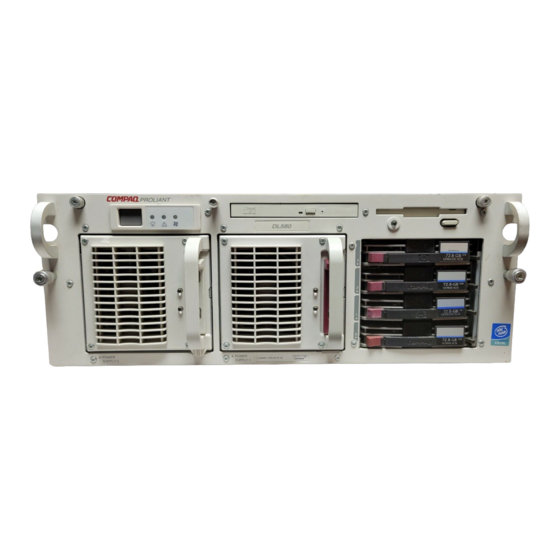
Chapter Server Features The Compaq ProLiant DL580 four-way server is housed in a modular, 7-inch rack-mount chassis that combines expandability with efficient and space-saving design. This chapter provides an overview of the Compaq ProLiant DL580 server features and briefly describes high availability, server management, and serviceability features. -
Page 15: System Features
Controller (NIC) card 4U form factor (7 in) Compaq ProLiant DL580 servers are designed with features and options to protect against hardware failure or data errors that can result in downtime or critical data loss. Maximum availability and manageability features include:... -
Page 16: Processors
Compaq authorized reseller or visit Compaq online: www.compaq.com/products/servers Expansion Slots There are a total of six PCI expansion slots in ProLiant DL580 to accommodate PCI Hot Plug and non-hot-plug options. The standard Compaq ProLiant DL580 configuration includes:... -
Page 17: Pci Hot Plug Capability
Reference Information pack with your server. Hot-Plug System Fans Compaq ProLiant DL580 servers include hot-plug fans that provide 24 x 7 protection against overheating and heat-related system interruptions. Under normal operating conditions, the system is served by four dual-fan units and stays cool with at least seven fans running. - Page 18 Server Features 1-5 Locating Hot-Plug Fans There are a total of eight fans mounted as four duplex fan units in the server as shown in the following illustration. Use the fan LED indicators to verify the activity on each unit. Figure 1-2.
- Page 19 1-6 Compaq ProLiant DL580 Server Setup and Installation Guide Front Panel Fan LED Front panel fan LEDs display a color-coded message about the status of the fans. The front panel fan LED is the third LED to the right of the Power On/Standby switch on the front of the server.
- Page 20 Server Features 1-7 Figure 1-4. Internal hot-plug fan LED locations Table 1-3 Internal Hot-Plug Fan LEDs Item Component Fan Assembly A LED Fan Assembly B LED Fan Assembly C LED Fan Assembly D LED...
-
Page 21: Media Bays
Media Bays Hot-Plug Drive Bay The Compaq ProLiant DL580 server supports one SCSI hard-drive cage that can be populated with up to four 1-inch standard hot-plug Ultra 2 SCSI hard drives, four Ultra 3 SCSI drives, or a combination of the two types. Drives of... -
Page 22: Power Supply Units
Server Features 1-9 Power Supply Units Compaq ProLiant DL580 servers ship standard with at least one hot-plug power supply (450 w at 220/110V) and support for an optional, redundant hot-plug power supply to provide system-wide backup power and the ability to balance power demands throughout the system. -
Page 23: Memory Board Features
Peripheral Board Features Compaq ProLiant DL580 servers feature a peripheral board that includes, as a standard feature, the Integrated Smart Array Controller. The peripheral board also supports system utilities and connectors including:... -
Page 24: Scsi
Options ROMPaq utility used to upgrade ROM Supported External Interfaces External SCSI (supporting tape drives only) Serial (one standard and one auxiliary) Video Parallel Hot-plug keyboard Mouse NOTE: Keyboard and mouse are not included as standard ProLiant DL580 features. -
Page 25: Network Interface Controller (Nic) Features
1-12 Compaq ProLiant DL580 Server Setup and Installation Guide Network Interface Controller (NIC) Features Compaq ProLiant DL580 servers include a Compaq NC3134 Fast Ethernet 64-bit Dual-Port 10/100 network interface controller (NIC) installed in PCI Hot Plug slot five. Features of the controller include:... -
Page 26: Serviceability Features
Improved diagnostics with memory and processor Internal Diagnostic Display (IDD) Server Management and Configuration Tools Compaq offers an extensive set of management features and optional tools to support effective server management and configuration including: Compaq SmartStart and Support Software CD Compaq System Configuration Utility... -
Page 27: Compaq Integrated Management Log
Compaq web-based management capabilities for Compaq ProLiant DL580 servers allow you to access your managed device list and the Compaq Insight Manager Alarm Log with a web browser, either locally at the management console or from another machine. If you have devices that are running Compaq Insight Manager Agents 4.7 or later, you can also view the... -
Page 28: Compaq Survey Utility
Server Features 1-15 Compaq has added two buttons to the Compaq Insight Manager button bar. One button launches your browser with the device list displayed, and the other button launches your browser with the alarm log displayed. For web-enabled devices (devices running Compaq Insight Manager Agents 4.7 and later), there is a shortcut in the task list for viewing web data. -
Page 29: Drive Fault Tolerance
1-16 Compaq ProLiant DL580 Server Setup and Installation Guide Drive Fault Tolerance Disk drive fault tolerance in Compaq servers is addressed in detail within the Compaq Server Online Reference Guide on the Documentation CD. Compaq ProLiant DL580 servers are configured with the Integrated Smart... -
Page 30: Compaq Operating System Utilities
Compaq utilities in that partition. Compaq Operating System Utilities Compaq servers take advantage of several utilities that provide detailed information and offer special capabilities including: Compaq PCI Hot Plug technology... -
Page 31: Compaq Integrated Remote Console
You can perform a wide range of configuration activities with the standard Compaq Integrated Remote Console (IRC) and an optional supported modem installed on the Compaq ProLiant DL580 server. Some IRC features include the following: Accessibility via an ANSI terminal... -
Page 32: Major Hardware Options
Server Features 1-19 Major Hardware Options Compaq ProLiant DL580 servers support several server hardware options available from a Compaq authorized reseller or service provider. Hardware option installation instructions are provided with each hardware option kit. For additional information on Compaq servers and options, visit the Compaq website: www.compaq.com/products/servers... -
Page 33: Front Panel Components
1-20 Compaq ProLiant DL580 Server Setup and Installation Guide Front Panel Components Use the following illustration to locate components on the front panel of your Compaq ProLiant DL580 server. Figure 1-6. Front panel components Table 1-5 Front Panel Components Item... -
Page 34: Rear Panel Components
Server Features 1-21 Rear Panel Components Use the following illustration to locate components on the rear panel of your Compaq ProLiant DL580 server. 6 5 4 3 2 1 Figure 1-7. Rear panel components Table 1-6 Rear Panel Components Item... -
Page 35: Diagnostics Tools
Controllers, depending on the installed network operating system. Each Smart Array 4200 Controller can support four Compaq StorageWorks Enclosures (Model 4314R). The Integrated Smart Array Controller, which ships standard on the ProLiant DL580, may be used for support of the internal hot-plug hard drives. Maximum SCSI Configuration... -
Page 36: Maximum Fibre Channel Configuration
A maximum Fibre Channel configuration optimizing performance and storage includes: One network interface controller (NIC) Five fibre channel host adapters Five Compaq StorageWorks FC-AL Switch 8 with 3-port Expansion Modules Fifty Compaq StorageWorks RAID Arrays (RA4000/4100) Six hundred 36.4-GB drives (twelve drives per array) This configuration yields a total external storage capacity of 21.84 TB... -
Page 37: Routine Maintenance
For information regarding routine maintenance and safety precautions, refer to the Documentation CD included in the Reference Information pack of the shipping box. Warranties For no additional cost, Compaq ProLiant DL580 servers include the following standard warranties: Three-Year Parts, Labor, and On-Site Limited Warranty Next Business Day Warranty... -
Page 38: Installing Hardware Options
Installing Hardware Options This chapter provides step-by-step instructions for installing optional hardware equipment in your Compaq ProLiant DL580 server. For additional instructions, refer to the installation instructions provided in each Compaq server option kit. Refer to the following documents for illustrated guides for... -
Page 39: Non-Hot-Plug Server Areas
2-2 Compaq ProLiant DL580 Server Setup and Installation Guide For information about upgrading your Compaq ProLiant DL580 server and obtaining the hot-plug and non-hot-plug options mentioned in this setup and installation guide, contact your Compaq authorized reseller or visit Compaq online: www.compaq.com/products/servers... -
Page 40: System Board Components
Installing Hardware Options 2-3 System Board Components Use the following illustration, along with your server setup poster, to locate system board components including slots, switches, and connectors. Refer to the illustrated labels attached to the inside of the server access panels for additional guidance in locating components. -
Page 41: Installing Non-Hot-Plug Options
2-4 Compaq ProLiant DL580 Server Setup and Installation Guide Table 2-1 System Board Components continued Item Component Item Component Service switch PCI Hot Plug expansion slot 4 Processor configuration PCI Hot Plug connector 5 (reserved for switch (SW4) NIC) PCI non-hot-plug... -
Page 42: Preparing To Install Non-Hot-Plug Options
Before installing a non-hot-plug hardware option: 1. Back up server data. NOTE: In a new Compaq ProLiant DL580 server, it is only necessary to back up data after installation and configuration is complete. 2. Shut down the operating system as directed in the operating system instructions. - Page 43 2-6 Compaq ProLiant DL580 Server Setup and Installation Guide IMPORTANT: The system power in the Compaq ProLiant DL580 server does not shut off completely from the front panel Power On/Standby switch. The two positions of the switch function as On and Standby, rather than On and Off. The Standby position removes power from most of the electronics and the drives;...
-
Page 44: Processors
Installing Hardware Options 2-7 Processors Compaq ProLiant DL580 servers ship standard with at least one processor and processor connectors on the server board that accommodate as many as four processors. When more than one processor is installed, both must operate at the same speed and frequency. - Page 45 2-8 Compaq ProLiant DL580 Server Setup and Installation Guide NOTE: In Compaq ProLiant DL580 servers, each Pentium III Xeon processor is keyed to fit into each processor slot one way only. Installing a Processor To install a processor, use the following procedure: 1.
- Page 46 NOTE: Processor slots are numbered 1 through 4 on the install labels and on the illustrated parts map. By default, Compaq ProLiant DL580 servers are shipped with at least one processor installed in slot 1. Remaining slots may be populated in any order.
- Page 47 2-10 Compaq ProLiant DL580 Server Setup and Installation Guide 7. Pull the blank out of its slot and retain it for future use. Figure 2-5. Removing the blanking panel from the processor slot 8. Align the new processor module with the processor slot and push the module into the slot 9.
- Page 48 Installing Hardware Options 2-11 NOTE: Processors are keyed to fit into the connector one way only. 11. Verify that the interlock LEDs indicate normal activity. See Appendix D for additional information about locating and reading LED indicators. CAUTION: If you remove a processor, the processor blanking panel must be reinstalled before powering up the server.
-
Page 49: System Memory
2-12 Compaq ProLiant DL580 Server Setup and Installation Guide System Memory You can expand the random access memory in your Compaq ProLiant DL580 server by adding additional DIMM modules. The standard system memory board with 16 DIMM slots supporting a multi-gigabyte capacity is shown in the following illustration. - Page 50 This type of design requires that four DIMM modules of the same size, type, and speed be installed or removed as a group. In Compaq ProLiant DL580 servers, the four groups containing four DIMM each on the memory board are referred to as banks 1 through 4.
- Page 51 2-14 Compaq ProLiant DL580 Server Setup and Installation Guide 2. On the memory board, squeeze in on the spring-loaded release latches and flip up the retaining flaps Figure 2-8. Removing the standard 16-DIMM memory board 3. Lift the board out of the server...
- Page 52 DIMM 12 DIMM 11 DIMM 14 DIMM 13 DIMM 16 DIMM 15 Figure 2-10. Locating DIMM slots on a 16-slot memory board CAUTION: Installing non-Compaq-approved DIMMs or DIMMs of different capacities undermines the effectiveness and integrity of the server’s processing memory.
- Page 53 2-16 Compaq ProLiant DL580 Server Setup and Installation Guide Reinstalling the Memory Board After securely installing the DIMM modules into the memory board, reinstall the memory board in the server by performing the following steps: 1. Align the memory board with the upright grooved supports and slide into place 2.
-
Page 54: Peripheral Board Components
Installing Hardware Options 2-17 Peripheral Board Components With the exception of the expansion slots, all of the Compaq ProLiant DL580 server’s data storage and transmission devices are managed through the peripheral board. Use the following illustration to locate components on the peripheral board shipped in your server. -
Page 55: Pci Non-Hot-Plug Expansion Board
2-18 Compaq ProLiant DL580 Server Setup and Installation Guide PCI Non-Hot-Plug Expansion Board The Compaq ProLiant DL580 server contains six PCI expansion slots, including two PCI non-hot-plug slots. Locating the PCI Expansion Slots The two PCI expansion slots are located directly beneath the PCI access panel. - Page 56 Installing Hardware Options 2-19 Use the following procedure to install an non-hot-plug expansion board in a PCI expansion slot. 1. Follow the procedures for “Preparing to Install Non-Hot-Plug Options” described earlier in this chapter. CAUTION: To reduce the risk of damage to your system or expansion boards, remove all AC power cords before installing or removing PCI expansion boards.
- Page 57 2-20 Compaq ProLiant DL580 Server Setup and Installation Guide 6. Insert the expansion board until the PCI retainer clip snaps closed. 7. Push the expansion slot latch in to secure the board. Figure 2-14. Inserting and securing an expansion board 8.
-
Page 58: Remote Insight Lights-Out Edition
PCI video functions. With the Remote Insight Lights-Out Edition installed in the Compaq ProLiant DL580 server, you can use a standard web browser and Compaq Insight Manager to access and remotely manage your server from any console on the network, regardless of the state of the host operating system. -
Page 59: Auxiliary Serial Connector
5. Power up the server and run the System Configuration Utility, if needed. Auxiliary Serial Connector You can configure a second serial device to your Compaq ProLiant DL580 server by installing the auxiliary serial connector that ships with your server. -
Page 60: Auxiliary Scsi Cable
Installing Hardware Options 2-23 1. Identify the auxiliary serial connector from the parts that shipped with your server. 2. Identify the auxiliary serial knockout available for installing the auxiliary serial connector on the rear of the server. 3. Follow the procedures for “Powering Down the Server” and “Removing the Access Panel”... - Page 61 2-24 Compaq ProLiant DL580 Server Setup and Installation Guide Compaq ProLiant DL580 server, refer to the documentation that ships with your option kit. Installing this option requires that you not cable your internal drive cage to SCSI port 1 on your peripheral board.
-
Page 62: Installing Pci Hot Plug Options
PCI Hot Plug Expansion Boards Compaq ProLiant DL580 servers support PCI Hot Plug technology and include four PCI Hot Plug expansion slots. The following requirements must be met in order for complete PCI Hot Plug capability to exist: PCI Hot Plug system hardware must be installed and available in your server. -
Page 63: Pci Hot Plug Utilities
The PCI Hot Plug utility software allows you to enable or disable specific slots to the system. Compaq, in partnership with Microsoft, Novell and SCO, has developed PCI Hot Plug software support for each operating system. - Page 64 Installing Hardware Options 2-27 Never remove a drive while another drive is being rebuilt. The online LED flashes green when a drive is being rebuilt. A replaced drive should be restored from data stored on the other drives. Never power down or turn off a ProLiant Storage System device while the server controlling it is powered on.
- Page 65 2-28 Compaq ProLiant DL580 Server Setup and Installation Guide 1. Locate and remove the blanking panel bay by squeezing the right retaining clip and pulling the blank out of the drive bay Figure 2-17. Removing a blanking panel 2. Insert the hot-plug SCSI hard drive into the empty drive bay and push until seated 3.
-
Page 66: Hot-Plug Power Supplies
Installing Hardware Options 2-29 CAUTION: Leaving a SCSI hard drive bay unpopulated interferes with proper airflow. Ensure that there is either a hard drive or a blank installed in each bay. Hot-Plug Power Supplies Locating and Installing Hot-Plug Power Supplies Use the following figure and table to locate the hot-plug power supply to be accessed. - Page 67 2-30 Compaq ProLiant DL580 Server Setup and Installation Guide Power Supply LEDs Note the color of the power supply LEDs located on the front of the power supply. A green light indicates power supply activity. Figure 2-20. Hot-plug power supply LEDs...
- Page 68 Installing Hardware Options 2-31 Removing a Hot-Plug Power Supply Hot-plug power supplies can be removed without powering down the server or backing up server data. 1. Grasp the power supply handle and pull up on the thumb latch out of the bay . 2.
-
Page 69: Integrated Smart Array Controller
Chapter Integrated Smart Array Controller This chapter provides an overview of the Compaq Integrated Smart Array Controller and its functions within the Compaq ProLiant DL580 server. Features The Compaq Integrated Smart Array Controller is a dual-channel Ultra2 SCSI array controller. Both channels support low voltage differential (LVD) SCSI devices. -
Page 70: External Scsi Connector
Figure 3-1. External SCSI connector on the rear panel To use a different Smart Array SCSI controller for managing internal hard drives, refer to the Compaq Integrated Smart Array Controller User Guide for information about installing a Smart Array/SCSI controller interface assemblies. -
Page 71: Installing The Server
Hardware installation service is available in all countries where Compaq has a direct or indirect service presence. It may be ordered from an authorized Compaq authorized reseller or, in the United States, by calling Compaq at 1-800-OK-COMPAQ. - Page 72 4-2 Compaq ProLiant DL580 Server Setup and Installation Guide Installing the server into the rack Attaching the cable management arm Cabling the server Powering up the server Powering down the server Installation Resources and Documentation Rack Builder Pro Configuration Tool and Rack Products Documentation resources provide information about rack designs and products.
-
Page 73: Rack Warnings And Precautions
This resource information on this CD allows you to view, search, and print documentation for Compaq racks and rack options. It also assists in the setup and optimization of your new Compaq rack to best fit the needs of your environment. - Page 74 CAUTION: Rack model Compaq ProLiant servers must always be operated with the top access panel secured in place. Proper cooling cannot be achieved while the system unit cover is removed.
-
Page 75: Installation Overview
See “Selecting an Optimum Environment” later in this chapter. The Installing Rack Products CD, the Rack Builder Configuration Tool, and the Rack Information Library all have information on how to do this. Information can also be downloaded from the Compaq website: www.compaq.com Unpack the server and rack mounting hardware. - Page 76 4-6 Compaq ProLiant DL580 Server Setup and Installation Guide Turn on the computer and insert the SmartStart and Support Software CD to configure and manage the server. When the server boots from the SmartStart program, it automatically starts the System Configuration Utility. See “Powering Up the Server”...
-
Page 77: Preparing The Server For Installation
Select an optimum environment Unpack the server Selecting an Optimum Environment When installing your Compaq ProLiant DL580 server in a rack, select a location that meets the following environmental standards. Space Requirements Clearance in the front of the rack should be a minimum of 25 inches for servicing and adequate airflow. - Page 78 “Listed” grounding-type devices. Due to the higher ground leakage currents associated with the equipment, Compaq recommends the use of a Power Distribution Unit (PDU) that provides a supplementary ground conductor. This supplementary ground conductor should be permanently connected to a suitable building ground terminal.
- Page 79 Airflow Requirements The Compaq ProLiant DL580 server draws cool air in through the front door and exhausts warm air out the rear. The front door of the rack must be adequately ventilated to allow ambient room air to enter the cabinet, and the rear door must be ventilated adequately to allow the warm air to escape from the cabinet.
-
Page 80: Unpacking The Server
Rack mounting hardware kit Hardware documentation, reference information, and software products Rack Mounting Hardware Kit Before mounting your Compaq ProLiant DL580 server in the rack, ensure that your rack model server box contains the mounting hardware shown in the following illustration. - Page 81 Installing the Server 4-11 Figure 4-1. Rack mounting hardware included with the server Table 4-2 Rack Mounting Hardware Item Component One pair 26-inch slide rail assemblies Rack mounting brackets Cable management arm bracket Cable management arm continued...
- Page 82 Cable management arm screw-retaining plate washer Rack template Documentation, Reference Information, and Software Products Before installing your Compaq ProLiant DL580 server, ensure that your server box contains the following documentation, reference information, and CDs: Documentation CD Compaq ProLiant Setup and Installation Guide...
-
Page 83: Attaching Rack Mounting Hardware
Installing the Server 4-13 Additional Tools and Materials In addition to these supplied items, you may need: Torx T-15 screwdriver Phillips screwdriver Cage nut fitting tool Pencil Optional components Attaching Rack Mounting Hardware Each pair of rack mounting brackets, with attached slide rail assemblies, supports one rack model server. -
Page 84: Attaching The Bracket Rail To The Rack Mounting Bracket
4-14 Compaq ProLiant DL580 Server Setup and Installation Guide Figure 4-3. Slide rail assembly with outer bracket rail and inner server rail IMPORTANT: To make the installation of the rack mounting bracket easier, attach the outer bracket rail to the rack mounting bracket before attaching the mounting bracket assembly to the rack. - Page 85 Installing the Server 4-15 Figure 4-4. Removing the server rail from the bracket rail 3. Set aside the server rails. You will attach them to the rack server chassis later in the section, “Attaching Server Rails to the Server.” Figure 4-5. Separated bracket rail with inner sliding piece (top) and server rail (bottom) 4.
- Page 86 4-16 Compaq ProLiant DL580 Server Setup and Installation Guide Figure 4-6. Bracket rail with inner slide 5. Identify the front of the rack mounting bracket and the bracket rail: the front of the rack mounting bracket has alignment tabs on its flange and the front of the bracket rail allows the inner slide to move forward on ball bearings.
- Page 87 The following figure shows insertion of the screws into the appropriate holes. Markings on the template identify the mounting holes for the 26-inch slides used in Compaq racks. Figure 4-7. Attaching the bracket rail to the rack mounting bracket 10. You will use a total of five 8-32 x 1/4-inch slotted screws to fasten the bracket rail to the rack mounting bracket.
-
Page 88: Using The Rack Template
4-18 Compaq ProLiant DL580 Server Setup and Installation Guide Figure 4-8. Replacing the server rail in the bracket rail 12. Repeat Steps 5 through 9 with the other bracket rail and rack mounting bracket. You now have a pair of mounting bracket slide assemblies to be attached to the rack. - Page 89 Installing the Server 4-19 Use the following procedure to mark screw hole locations for the rack mounting bracket assemblies and fastener positions for the cage nuts: 1. Identify the front side of the template. IMPORTANT: The template is two-sided (front and back) and printed with arrows that show you where the screws are inserted, both for the mounting bracket assemblies and for the thumb screws that secure the server's faceplate to the front of the rack.
-
Page 90: Attaching The Rack Mounting Bracket Assemblies To The Rack
4-20 Compaq ProLiant DL580 Server Setup and Installation Guide Inserting Cage Nuts into the Rack Frame After marking the faster positions on both front and back of the rack, use the fitting tool to insert cage nuts on the inside of the rails at the marked locations. - Page 91 Installing the Server 4-21 3. Secure the rack mounting bracket using two M6 x 12mm Phillips-head screws. CZR4-012.eps Figure 4-11. Back of mounting bracket assembly installed 4. Using the pencil marks, attach the rack mounting bracket assembly to the front rail of the rack using one M6 x 12mm Phillips-head screw in the top hole of the bracket.
-
Page 92: Attaching Rack Handles
4-22 Compaq ProLiant DL580 Server Setup and Installation Guide Figure 4-12. Attaching rack mounting bracket assembly to the front of the rack 5. To install the second rack mounting bracket assembly, repeat Step 1 through Step 4. 6. After attaching both of the rack mounting bracket assemblies to the rack, prepare the server for mounting. -
Page 93: Installing The Server In The Rack
WARNING: To reduce the risk of personal injury or damage to the equipment, a minimum of two people must lift the server onto the slide rails. A Compaq ProLiant DL580 server can weigh up to 81 lb (37 kg). 3. Align the server screw holes with the slide-rail screw holes. - Page 94 4-24 Compaq ProLiant DL580 Server Setup and Installation Guide Figure 4-14. Loading the server with handles into the rack 4. Attach the server to the slide rails with three screws on each side. Begin with the back screw hole, and then adjust the inner slide rail and server together to access the other screw holes through the slotted opening in the inner slide.
-
Page 95: Attaching The Cable Management Arm
Installing the Server 4-25 Attaching the Cable Management Arm After the server is mounted in the rack, begin installing hardware for cable management. Rack mounting hardware provided with your server includes a cable management arm, fasteners, hinges, and screws. The cable management arm attaches to the server's cable management arm bracket and to the rear frame of the rack. -
Page 96: Attaching The Cable Management Arm
4-26 Compaq ProLiant DL580 Server Setup and Installation Guide Attaching the Cable Management Arm After installing the extended cable management arm bracket, use the following procedure to attach the cable management arm. 1. For easier handling, first slide the server into the rack. Next attach the cable management arm to the cable management arm bracket. -
Page 97: Cabling The Server
Installing the Server 4-27 Figure 4-17. Attaching the cable management arm screw-retaining plate 4. Attach the cable management arm to the retaining plate on the rear frame rail of the rack with two 10-32 x 5/8-inch Phillips-head screws. Figure 4-18. Attaching the cable management arm to the rear brace of the rack Cabling the Server After installing the server in the rack and attaching the cable management arm,... - Page 98 4-28 Compaq ProLiant DL580 Server Setup and Installation Guide 2. Tie-wrap the AC cord to the plastic loop provided on the power supply to prevent the cord from being accidentally disengaged. Figure 4-19. Securing the AC power cord with tie-wrap...
- Page 99 Installing the Server 4-29 WARNING: Do not place anything on power cord(s) or cables. Arrange them so that no one may accidentally step on or trip over them. Do not pull on a cord or cable. When unplugging from the electrical outlet, grasp the cord by the plug. WARNING: To reduce the risk of electric shock or fire, do not plug telecommunications/telephone connectors into the Network Interface Card (NIC) receptacles.
-
Page 100: Powering Up The Server
Powering Up the Server After completing all of the installation procedures described above, you are ready to configure your Compaq ProLiant DL580 server as a stand-alone or network device. After ensuring that all connections are secure and that the rack is stable, press the Power On/Standby switch to power up the server for the first time. -
Page 101: Powering Down The Server
Installing the Server 4-31 Powering Down the Server The system power in the Compaq ProLiant DL580 server does not shut off completely with the front panel Power On/Standby switch. The two positions of the switch function as on and standby, rather than on and off. The standby position removes power from most of the electronics and the drives, but portions of the power supply and some internal circuitry remain active. -
Page 102: Cabling Guidelines
Chapter Cabling Guidelines This chapter discusses connections and cabling considerations for the Compaq ProLiant DL580 server. Use the connector and cabling examples as a guide for cabling the following components: Network interface controller (NIC) External connectors SCSI cabling PCI Hot Plug cabling... - Page 103 5-2 Compaq ProLiant DL580 Server Setup and Installation Guide For 10Base-T, your network cable must be Category 3, 4, or 5 twisted-pair wiring. If you want to use this NIC in a residential environment, you must use a Category 5 cable.
-
Page 104: External Connectors
Cabling Guidelines 5-3 External Connectors External connectors to peripheral devices and other network options are shown in the following figure. 6 5 4 3 2 1 Figure 5-2. External connectors on the rear of the server Table 5-1 Rear Panel Connectors Item Component Auxiliary serial knockout... -
Page 105: Scsi Cabling
Wide Ultra SCSI adapters may be added for an expanded range of SCSI configurations. SCSI Ports The Compaq ProLiant DL580 server includes two SCSI ports located on the peripheral board. SCSI port 1 supports the Wide Ultra2/Ultra3 SCSI hard drive cage. -
Page 106: Determining Cabling Needs
SCSI components you plan to install. NOTE: Your Compaq ProLiant DL580 server includes all SCSI cables required for connecting the SCSI devices shipped with your factory-built server. Compaq SCSI option kits also contain all required installation hardware. For information on obtaining additional server connectors and supplies, contact your Compaq authorized reseller. -
Page 107: Internal Cabling With An Integrated Controller Or An Additional Scsi Adapter
5-6 Compaq ProLiant DL580 Server Setup and Installation Guide Internal Cabling with an Integrated Controller or an Additional SCSI Adapter IMPORTANT: Do not leave unterminated cables connected to an internal SCSI port. Proper SCSI bus termination requires that each connector is either connected to a SCSI device with an appropriate cable or is unpopulated and capped with a safety cover. -
Page 108: Pci Hot Plug Cabling
WARNING: Before removing the top access panel, make sure that the server is powered down or in Standby mode, and that all power connections are disconnected from the server. The system power in Compaq ProLiant DL580 servers does not completely shut off from the front panel Power On/Standby switch. -
Page 109: Securing The Power Cord
5-8 Compaq ProLiant DL580 Server Setup and Installation Guide WARNING: To reduce the risk of electric shock or damage to the equipment: If the system has multiple power supplies, disconnect power from the system by unplugging all power cords from the power supplies Do not disable the power cord grounding plug. -
Page 110: Pci Hot Plug Technology
PCI Hot Plug Administration Guide and the PCI Hot Plug animation provided on the Documentation CD. Compaq ProLiant DL580 servers support PCI Hot Plug capabilities. This technology works with the operating system to provide the capacity for performing hardware operations while the server is active. -
Page 111: Pci Hot Plug Capability
Documentation provided with the SCSI drives for installation information and controller configuration. Information about the compatibility of SCSI controllers with SCSI drives in the Compaq ProLiant DL580 from the Compaq website: www.compaq.com/products/servers Information about SCSI cabling in Chapter 5, “Cabling Guidelines.”... -
Page 112: Pci Hot Plug Technology
PCI Hot Plug Technology 6-3 PCI Hot Plug Technology PCI Hot Plug System A PCI Hot Plug enabled system requires that the appropriate system hardware, operating system, and device driver support all be enabled. An existing adapter board should be hot-plug capable as long as it complies with the established PCI specifications and has hot-plug device driver support. -
Page 113: Pci Hot Plug Leds
6-4 Compaq ProLiant DL580 Server Setup and Installation Guide PCI Hot Plug LEDs The PCI Hot Plug LEDs at each expansion slot provide a visual reference of the status of each board slot. The LEDs are viewed from the rear of the server or by opening the PCI Hot Plug access door on the top panel. - Page 114 PCI Hot Plug Technology 6-5 Table 6-2 PCI Hot Plug LED Status Indicators Power Status OK to Open Slot Status Power is currently applied to the slot. Do NOT Green open the slot release lever. The slot is Amber functioning normally. Power is currently applied to this slot, but the Green slot needs ATTENTION for possible problems...
-
Page 115: Adding Or Replacing Pci Hot Plug Expansion Boards
6-6 Compaq ProLiant DL580 Server Setup and Installation Guide Table 6-2 PCI Hot Plug LED Status Indicators continued Power Status OK to Open Slot Status The power to the slot is Off. If you need to Green replace the card in this slot, follow these... -
Page 116: Removing A Pci Hot Plug Expansion Board
PCI Hot Plug Technology 6-7 Removing a PCI Hot Plug Expansion Board WARNING: Reduce the risk of personal injury from hot surfaces by allowing all internal system components to cool before working with them. To remove a PCI expansion board, complete the following procedure: 1. - Page 117 6-8 Compaq ProLiant DL580 Server Setup and Installation Guide Figure 6-3. PCI Hot Plug button and LED indicators CAUTION: DO NOT open the slot release lever unless the green LED indicator is off. Releasing the lever before power is off can cause a complete loss of system power and data.
-
Page 118: Installing A Pci Hot Plug Expansion Board
PCI Hot Plug Technology 6-9 Installing a PCI Hot Plug Expansion Board IMPORTANT: Do not scrape the PCI Hot Plug expansion board against any other component. 1. Install the same type of PCI expansion board into the same expansion slot, pushing firmly until it is seated securely 2. -
Page 119: Pci Hot Plug Application Support
In partnership with Microsoft and Novell, Compaq has developed software support implementations for each company’s operating system. SCO support will be available soon; check for availability on the Compaq website: www.compaq.com Compaq is promoting standardization with these operating system software leaders to ensure the broad availability of PCI Hot Plug technology. -
Page 120: Performing Pci Hot Plug Actions
PCI Hot Plug Technology 6-11 Performing PCI Hot Plug Actions The Compaq PCI Hot Plug and the intraNetWarePCI Hot Plug application work together to allow the following PCI Hot Plug actions: Hot removal of adapters You can manually shut down and permanently remove an adapter, regardless of whether it is working or has failed. - Page 121 6-12 Compaq ProLiant DL580 Server Setup and Installation Guide 3. Once the new adapter is detected, NCMCON automatically asks if you want to configure and apply power to the slot. If you answer yes, power is applied to the slot, the green LED is lit, and the status of the slot on the console changes to Ready.
-
Page 122: Pci Hot Plug Utility For Windows Nt
PCI Hot Plug Technology 6-13 PCI Hot Plug Utility for Windows NT The Compaq PCI Hot Plug Utility for Windows NT allows you to view the status of the PCI Hot Plug slots and to initiate actions such as replacing a failed card. -
Page 123: Compaq Pci Hot Plug Utility Messages
4. In the PCI Hot Plug utility, turn the power on for the slot by selecting it and clicking the power button. Compaq PCI Hot Plug Utility Messages The requested machine is not running the Compaq Remote Control service. You cannot connect to the specified machine because it is not running the Compaq Remote Control service. -
Page 124: Server Configuration And Utilities
Chapter Server Configuration and Utilities This chapter describes the software tools that Compaq provides on your SmartStart and Support Software CD (SmartStart CD) to assist you in configuring and managing your Compaq ProLiant DL580 server. SmartStart Features Compaq SmartStart provides intelligent tools for configuring your server and loading system software to achieve a well-integrated server with optimal dependability and supportability. -
Page 125: Compaq System Configuration Utility
The System Configuration Utility uses option configuration (.CFG) files to configure the server. These files contain: IRQs Software installation guidelines PCI board resource requirements The .CFG files for Compaq servers reside on System Configuration diskettes or on the SmartStart CD. -
Page 126: Launching The Smartstart Cd
Select either the ROMPaq or System Configuration Utility. Reapplying ROMPaq In Compaq ProLiant DL580 servers, the system ROM is automatically configured after any memory or processor changes. To re-apply your default system ROM using ROMPaq, open the SmartStart folder on the... -
Page 127: Loading System Configuration Utility
Configuration Utility and other Compaq utilities into that partition. You can work with the utilities immediately from your local drives. IMPORTANT: Do not confuse the Compaq System Utility partition with system partitions created by your operating system. When you use Compaq System Configuration Utility to reconfigure or troubleshoot, make sure that the SmartStart CD is available. -
Page 128: System Configuration Utility Main Menu
Server Configuration and Utilities 7-5 System Configuration Utility Main Menu Use the System Configuration Utility main menu to set power-on features and perform a range of system configuration tasks. Main Menu Main menu options include: System configuration Operating system installation Diagnostics and utilities Exit System Configuration... -
Page 129: System Configuration Menu
7-6 Compaq ProLiant DL580 Server Setup and Installation Guide System Configuration Menu Select System Configuration from the main menu and choose among the following options in the system configuration menu: Configure hardware Power-on defaults System partition Configuration backup Configure Hardware Select this option to set configuration preferences manually. - Page 130 Server Configuration and Utilities 7-7 Power-On Defaults You can change the default time, date, and number lock settings of your system by selecting the Power-On Defaults option from the System Configuration Utility main menu. Set the default beginning date MM-DD-YYYY Set the default beginning time HH:MM:SS Set the default status for your numeric keypad...
- Page 131 7-8 Compaq ProLiant DL580 Server Setup and Installation Guide Creating and Verifying a System Partition If you used SmartStart to configure your server and install your operating system, SmartStart automatically performed this procedure for you. IMPORTANT: Use this procedure only if the operating system was not installed on the server and you wish to create a system partition.
- Page 132 Server Configuration and Utilities 7-9 IMPORTANT: The text is displayed for only two seconds. If you do not press F10 within the two seconds, you must start the server again. d. If a system partition exists, the server powers up to the partition. If the partition does not exist, the message displayed indicates that no system partition exists.
- Page 133 7-10 Compaq ProLiant DL580 Server Setup and Installation Guide 2. Select the System Configuration option from the System Configuration Utility menu. 3. Select the System Partition option and then the Copying Files option. The System Configuration Utility then displays the available configuration files with the following commands: Press Space to mark files for copying.
- Page 134 Server Configuration and Utilities 7-11 Configuration Backup The Configuration Backup option from the System Configuration menu allows you to Create a backup of the system configuration Restore the system configuration from the backup Backing Up to a System Configuration Saving and exiting from the System Configuration Utility generates a history of the configuration.
- Page 135 7-12 Compaq ProLiant DL580 Server Setup and Installation Guide The following table describes each of the .SCI and .CHL files maintained by your System Configuration Utility. Table 7-1 System Configuration History Log Files Filename Description SYSTEM.SCI Current configuration information SYSTEM1.SCI Previous configuration information SYSTEM2.SCI...
- Page 136 Server Configuration and Utilities 7-13 If you choose to execute the restoration, the System Configuration Utility will restore the configuration settings you chose and advise you when the restoration is complete. 4. Select from the following options: Save the configuration and reboot the system. Review and modify your configuration settings.
-
Page 137: Installing An Operating System
If present, these files may contain information about important software updates. Novell NetWare Device Drivers from Compaq To operate NetWare, your Compaq ProLiant DL580 server must maintain certain device drivers, located on the SmartStart CD shipped with the server. If you use SmartStart to install the operating system, these drivers are installed automatically. - Page 138 Microsoft Windows Device Drivers from Compaq To support Microsoft Windows NT 4.0 and Windows 2000 operating systems, Compaq provides drivers on the SmartStart CD, some of which are contained within the Windows NT retail product. Drivers on the Support Software Diskettes (SSD) may be newer versions and may include new functionality and problem fixes.
- Page 139 Dual Channel Wide Ultra2/Ultra3 SCSI Adapters IMPORTANT: Use the following procedure when you power up the server from the Microsoft Windows NT 4.0 CD and install your operating system on the Compaq ProLiant DL580 server with a 64-bit Dual Channel Wide-Ultra2/Ultra3 SCSI Adapter The Microsoft Windows NT 4.0 CD does not contain the required drivers for proper...
- Page 140 Select the appropriate Compaq HAL for your server (SystemPro Multiprocessor, MPS Multiprocessor, or Uniprocessor). g. Insert the Compaq Server Support for Microsoft Windows NT 4.0, Disk 2 into the diskette drive and press Enter. You have now completed the installation of the Compaq HAL.
- Page 141 7-18 Compaq ProLiant DL580 Server Setup and Installation Guide 2. Follow the instructions on the screen, until you reach the step to detect mass storage devices. 3. To skip mass storage device detection, select S for Skip detection. 4. When prompted to specify additional SCSI adapters or array controllers, select S for Specify Additional Devices.
- Page 142 IMPORTANT: For procedures to configure external storage devices, please refer to the documentation shipped with your storage device or refer to the Compaq web site: www.compaq.com Before You Begin IMPORTANT: Use these instructions only with Compaq ProLiant DL580 servers.
- Page 143 7-20 Compaq ProLiant DL580 Server Setup and Installation Guide SmartStart Assisted-Path Installation for Windows 2000 IMPORTANT: The SmartStart assisted-path installation can only be used when the server uses an installed array controller. The SmartStart CD provides assistance for installing and configuring Microsoft Window 2000 as your operating system.
- Page 144 SmartStart Manual-Path Installation for Windows 2000 The manual-path installation method requires these steps: Create the Compaq Support Software for Microsoft Windows 2000 Install the Windows 2000 operating system For more information on device drivers, run the README.BAT file in the root directory of the Software and Support CD for Windows 2000 to read the WinHelp file NTREADME.HLP.
- Page 145 Drivers from Compaq To support the SCO OpenServer or SCO UnixWare operating systems, your Compaq ProLiant DL580 server must have certain device drivers, located on the SmartStart CD shipped with your server. The following features require the installation of these device drivers:...
- Page 146 Sun Solaris Intel Platform Edition Device Drivers for Compaq To operate with Sun Solaris Intel Platform Edition 2.6 and 7, your Compaq ProLiant DL580 server must maintain certain device drivers. You can access the drivers and installation procedures for Solaris 2.6 at the Sun website: www.soldc.sun.com/support/drivers/...
-
Page 147: Diagnostics And Other Utilities
Utility menu prompts the system to test, inspect, upgrade, and diagnose the server. The Compaq ProLiant DL580 server maintains the diagnostics and other utilities in the system partition on the hard drive, and accesses these utilities when a system configuration error is detected during the POST. -
Page 148: Integrated Management Log (Iml)
The ability to view events occurring to these components allows you to take immediate action. You can view and print the event list from within Compaq Insight Manager by following the instructions below. You can also mark a critical or caution event... - Page 149 7-26 Compaq ProLiant DL580 Server Setup and Installation Guide failed fan has been replaced. You can lower the severity of the event by marking it as repaired. Viewing the Event List To view the list, follow the instructions below: 1. Select the appropriate server from Compaq Insight Manager.
-
Page 150: List Of Events
The Compaq Survey Utility for Windows NT and Novell NetWare is a serviceability tool that delivers online configuration capture and comparison to maximize server availability. It is available on the Compaq Management CD in the Server Setup and Management package, or it is available on the Compaq website: www.compaq.com Refer to the Compaq Management CD for information on installing and running the Survey Utility. - Page 151 7-28 Compaq ProLiant DL580 Server Setup and Installation Guide Main Memory Correctable error Corrected Memory Error threshold passed (Slot X, Memory threshold exceeded Module X) Corrected Memory Error threshold passed (System Memory) Corrected Memory Error threshold passed (Memory Module unknown)
- Page 152 Server Configuration and Utilities 7-29 Table 7-2 Event Messages continued Event Type Event Message Power Subsystem Power supply failure System Power Supply Failure (Power Supply X) Power supply inserted System Power Supply Inserted (Power Supply X) Power supply removed System Power Supply Removed (Power Supply X) Power supply not System Power Supplies Not Redundant redundant...
-
Page 153: Regulatory Compliance Notices
Compaq ProLiant DL580 server is assigned a Compaq series number. The Compaq series number for this product is Series ES1015. The Compaq ProLiant DL580 server series number can be found on the product label, along with the required approval markings and information. When requesting certification information for this product, always refer to this series number. -
Page 154: Federal Communications Commission Notice
A-2 Compaq ProLiant DL580 Server Setup and Installation Guide Federal Communications Commission Notice Part 15 of the Federal Communications Commission (FCC) Rules and Regulations has established Radio Frequency (RF) emission limits to provide an interference-free radio frequency spectrum. Many electronic devices, including computers, generate RF energy incidental to their intended function and are, therefore, covered by these rules. -
Page 155: Class B Equipment
Regulatory Compliance Notices A-3 Class B Equipment This equipment has been tested and found to comply with the limits for a Class B digital device, pursuant to Part 15 of the FCC Rules. These limits are designed to provide reasonable protection against harmful interference in a residential installation. -
Page 156: Modifications
Modifications The FCC requires the user to be notified that any changes or modifications made to this device that are not expressly approved by Compaq Computer Corporation may void the user's authority to operate the equipment. Cables Connections to this device must be made with shielded cables with metallic RFI/EMI connector hoods in order to maintain compliance with FCC Rules and Regulations. -
Page 157: Class B Equipment
Regulatory Compliance Notices A-5 Class B Equipment This Class B digital apparatus meets all requirements of the Canadian Interference-Causing Equipment Regulations. Cet appareil numérique de la classe B respecte toutes les exigences du Règlement sur le matériel brouilleur du Canada. Mouse Compliance Statement This device complies with Part 15 of the FCC Rules. -
Page 158: Japanese Notice
Japanese Notice Taiwanese Notice Laser Devices All Compaq systems equipped with a laser device comply with safety standards, including International Electrotechnical Commission (IEC) 825. With specific regard to the laser, the equipment complies with laser product performance standards set by government agencies as a Class 1 laser product. -
Page 159: Laser Safety Warnings
All Compaq systems equipped with laser devices comply with appropriate safety standards including IEC 825. Laser Product Label The following label or equivalent is located on the surface of the Compaq supplied laser device. This label indicates that the product is classified as a CLASS 1 LASER PRODUCT. -
Page 160: Laser Information
Your computer is provided with an internal Lithium battery or battery pack. There is a danger of explosion and risk of personal injury if the battery is incorrectly replaced or mistreated. Replacement is to be done by a Compaq authorized service provider using the Compaq spare designated for this product. -
Page 161: Power Cords
18AWG, and the length of the cord must be between 6 feet (1.8 m) and 12 feet (3.6 m). If you have questions about the type of power cord to use, contact your Compaq authorized service provider. Route power cords so that they will not be walked on, or pinched by, items placed upon them or against them. -
Page 162: Electrostatic Discharge
Appendix Electrostatic Discharge To prevent damaging the system, be aware of the precautions you need to follow when setting up the system or handling parts. A discharge of static electricity from a finger or other conductor may damage system boards or other static-sensitive devices. -
Page 163: Grounding Methods
B-2 Compaq ProLiant DL580 Server Setup and Installation Guide Grounding Methods There are several methods for grounding. Use one or more of the following methods when handling or installing electrostatic-sensitive parts: Use a wrist strap connected by a ground cord to a grounded workstation or computer chassis. -
Page 164: Appendix C Troubleshooting
Appendix D for the locations of system status LEDs. Ensure that the Power On/Standby switch was pressed firmly. Refer to the “Power Source” section in the Compaq Servers Troubleshooting Guide for details on other checkpoints. 3. Ensure that all power supplies are working properly. - Page 165 5. If the server is power cycling, verify that the Automatic Server Recovery-2 (ASR-2) utility has restarted the system in response to another problem. In the Compaq Servers Troubleshooting Guide, refer to sections on the Automatic Server Recovery-2 (ASR-2). Also refer to the “System Short” section in the same guide.
-
Page 166: Normal Power-Up Sequence
Troubleshooting C-3 Normal Power-Up Sequence The following sequence of events occurs when a system meeting the minimal hardware requirements is powered up under normal operating conditions. 1. The front panel Power On/Standby LED turns from amber (standby) to green (on). 2. - Page 167 C-4 Compaq ProLiant DL580 Server Setup and Installation Guide Table C-1 Diagnosis Steps Question Action Question 1: Are any front panel system status If no, go to Table C-2. LEDs on? If yes, continue to Question 2. Question 2: Is the Power On/Standby status LED If amber and on, go to Table C-3.
- Page 168 There is a broken connection between the Check the power switch cable for bent pins. Try system and backplane. reconnecting the power switch cable. Refer to “Power Problems” in the Compaq Servers Troubleshooting Guide for further options.
- Page 169 C-6 Compaq ProLiant DL580 Server Setup and Installation Guide Table C-3 Power On/Standby Status LED is Amber See “Front Panel LEDs” in Appendix D Possible Reasons Next Steps Power switch was not fully depressed on Try pressing the power switch until it is fully initial power-up.
- Page 170 A series of beeps will be the audible signal indicating the presence of a Power-On Self-Test (POST) error message. Refer to “POST Error Messages” in the Compaq Servers Troubleshooting Guide for a complete description of each beep sequence and the corresponding error message.
- Page 171 C-8 Compaq ProLiant DL580 Server Setup and Installation Guide Table C-6 Memory/Processor Status LED is Blinking Amber See “Front Panel LEDs” in Appendix D. Possible Reasons Next Steps Memory is not present or Place the server in standby mode by pressing the Power On/Standby is not seated properly.
-
Page 172: Problems After Initial Startup
*CAUTION: The Compaq System Erase Utility causes loss of all configuration information, as well as loss of existing data on all connected hard drives. Please read “Running the Compaq System Erase Utility” and the associated warning in the Compaq Servers Troubleshooting Guide before performing this operation. - Page 173 C-10 Compaq ProLiant DL580 Server Setup and Installation Guide Table C-7 Installation Problems continued Problem Possible Cause Possible Solution Server cannot Required operating Note the phase at which the operating system failed. load operating system step was Remove any loaded operating system.
-
Page 174: Hot-Plug Fans
Troubleshooting C-11 Hot-Plug Fans The eight fans in Compaq ProLiant DL580 servers comprise a nonredundant cooling system. This system is functional with as few as seven fans. With fewer than seven fans running, the server will automatically shut down until the missing fans are replaced. - Page 175 C-12 Compaq ProLiant DL580 Server Setup and Installation Guide Figure C-1. Hot-plug fan locations Table C-9 Hot-Plug Fan Locations Item Component Fan Identifiers Fan Assembly A Fans 1 and 2 Fan Assembly B Fans 3 and 4 Fan Assembly C...
- Page 176 Troubleshooting C-13 Figure C-2. Hot-plug fan LED locations Table C-10 Hot-Plug Fan LEDs Item Component Fan Assembly A LED Fan Assembly B LED Fan Assembly C LED Fan Assembly D LED Table C-11 Hot-Plug Fan LED Status LED Indicator Status No light Power is not applied to the fan.
- Page 177 C-14 Compaq ProLiant DL580 Server Setup and Installation Guide Removing Hot-Plug Fans WARNING: To reduce the risk of personal injury from hazardous energy or damage to the equipment when working on active servers: Remove all watches, rings, and any other loose fitting jewelry.
- Page 178 Troubleshooting C-15 Installing a Hot-Plug Fan This procedure can be used after the server is powered down or during live activity. To ensure safety, is recommended that hot-plug fans be replaced when the server is powered down. 1. Lower the new hot-plug fan into the fan bracket until it is seated securely in the hot-plug fan slot on the system board.
-
Page 179: Led Indicators
Appendix LED Indicators Compaq ProLiant DL580 servers contain a number of LED indicators that provide a visual reference to the status of various server components. Use this appendix as a quick reference for recognizing LED locations and status indications and meanings. -
Page 180: Hot-Plug Scsi Hard Drive Leds
D-2 Compaq ProLiant DL580 Server Setup and Installation Guide Figure D-1. Front panel LEDs Table D-1 Front Panel LEDs Description Indicator Status Power/Interlock Green Amber Standby Amber/blinking Interlock or shutdown Memory/Processor Green Amber/blinking Memory or processor failure Fans Green Amber/blinking... - Page 181 Servers Troubleshooting Guide before removing a hard drive For additional information on troubleshooting hard drive problems, refer to “Hard Drive Problems” and “SCSI Device Problems” in the Compaq Servers Troubleshooting Guide. Use the following illustration and table to assist in analyzing the functional status of hot-plug hard drives managed through the Compaq Integrated Smart Array Controller.
- Page 182 D-4 Compaq ProLiant DL580 Server Setup and Installation Guide Table D-2 Hard Drive LED Indicator Status Combinations Means Activity Online Fault Do not remove the drive. Removing a drive during this process will cause data loss. The drive is being accessed and is not configured as part of an array.
- Page 183 LED Indicators D-5 Table D-2 Hard Drive LED Indicator Status Combinations continued Means Activity Online Fault OK to replace the drive online. The drive has failed and has been placed off-line. OK to replace the drive online if a predictive failure alert is received (see the following section for details), provided that the array is configured for fault tolerance and all other drives in the array are online.
-
Page 184: Hot-Plug Fan Leds
D-6 Compaq ProLiant DL580 Server Setup and Installation Guide Hot-Plug Fan LEDs In Compaq ProLiant DL580 servers, the eight hot-plug system fans are installed as dual-fan assemblies. Each assembly is monitored by an LED attached to the system board and read from the light see at the top of the assembly inside the chassis. -
Page 185: Hot-Plug Fan Leds
LED Indicators D-7 Hot-Plug Fan LEDs The hot-plug fan LED provides a visual reference for the status of each fan. View the LED by opening the primary hot-plug door on the access panel. Verify the status of the fans by noting the color of the LED at the fan location. Figure D-3. -
Page 186: Power Supply Leds
D-8 Compaq ProLiant DL580 Server Setup and Installation Guide Power Supply LEDs Determine the power supply status by noting the color of the LED on the power supply unit. The following table defines the status colors. Figure D-4. Power supply LEDs... -
Page 187: Pci Hot Plug Leds
LED Indicators D-9 PCI Hot Plug LEDs The PCI Hot Plug LEDs at each expansion slot provide a visual reference of the status of each board slot. The LEDs are viewed from the rear of the server or by opening the PCI Hot Plug access door on the top panel. The following figure and table illustrate the appropriate slot conditions and status for each of the two LEDs. - Page 188 D-10 Compaq ProLiant DL580 Server Setup and Installation Guide Table D-7 PCI Hot Plug LED Status Indicators Power Status OK to Open Slot Status Power is currently applied to the slot. Do NOT open Green the slot release lever. The slot is functioning Amber normally.
- Page 189 LED Indicators D-11 Table D-7 PCI Hot Plug LED Status Indicators continued Power Status OK to Open Slot Status The power to the slot is Off. If you need to replace Green the card in this slot, follow these steps: Amber 1.
-
Page 190: Rj-45 Network Connector Leds
D-12 Compaq ProLiant DL580 Server Setup and Installation Guide RJ-45 Network Connector LEDs Figure D-7. RJ-45 network connector LEDs Table D-9 RJ-45 Network Connector Status LED Status Description No network link Link Linked to network No network activity Activity On or Flashing... -
Page 191: Internal Diagnostic Display (Idd
LED Indicators D-13 Internal Diagnostic Display (IDD) The IDD indicates the failure of a memory module or processor. It displays a two-digit alphanumeric code that corresponds to a specific memory module or processor. For an understanding of IDD status indicators, see the following table. - Page 192 D-14 Compaq ProLiant DL580 Server Setup and Installation Guide Table D-10 Internal Diagnostic Display (IDD) Status Messages Status Means No failure detected Memory module 01 failure Memory module 02 failure Memory module 03 failure Memory module 04 failure Memory module 05 failure...
-
Page 193: Interlock Status Led Indicators
The following illustration and table identify the location of the interlock LED indicators and the point of the hardware connection fault. IMPORTANT: Compaq ProLiant DL580 servers are not equipped with chassis door or access panel interlocks. Figure D-9. Interlock LED indicators on the system board... - Page 194 D-16 Compaq ProLiant DL580 Server Setup and Installation Guide Table D-11 Interlock LED Indicators continued Fault of Interlock Error Processor 4 Peripheral board Power supply backplane board No interlock error Note: Reseat the indicated device and restart the server.
-
Page 195: Switch Settings
If the switch configurations are incorrect, the system may not work properly and may display error messages. Setting and verifying the system board switches is an important part of the overall troubleshooting process. Compaq ProLiant DL580 servers have three switch banks: SW1—a six-position system maintenance switch on the peripheral board SW4—a four-position processor configuration switch on the system... -
Page 196: System Maintenance Switch (Sw1
E-2 Compaq ProLiant DL580 Server Setup and Installation Guide System Maintenance Switch (SW1) The system maintenance switch (SW1): Disables the embedded video in the system Designates rack-mount or tower configurations Enables or disables the diskette boot option Enables or disables power-on password protection... - Page 197 Switch Settings E-3 Table E-1 System Maintenance Switch (SW1) Position Default Function Description Settings Video disable override Used when ROM Open (off) does not detect an ROM will auto-detect an installed video card. optional video card. If no optional card is detected, on-board video is enabled.
-
Page 198: Enabling Rompaq Disaster Recovery Mode
Set configuration switches 1, 4, 5, and 6 on the system maintenance switch block to On to enable disaster mode. IMPORTANT: Before enabling ROMPaq disaster recovery mode, refer to the Compaq Servers Troubleshooting Guide for complete instructions on disaster recovery. -
Page 199: Processor Configuration Switch (Sw4
Switch Settings E-5 Processor Configuration Switch (SW4) This switch is used to select the front-side bus-to-processor ratio. Factory default settings are provided to match the speed of your installed Pentium III Xeon processor. Figure E-2. Processor configuration switch (SW4) Table E-2 Processor Configuration Switch (SW4) Processor/Front-side Bus Position... -
Page 200: Processors Of 850-Mhz Frequency Or Higher
CAUTION: Improper use of this switch can damage system components. Do not change this switch from the indicated default settings. The service switch is used only during the course of service or repair by Compaq authorized service providers. Figure E-3. Service switch (SW6) - Page 201 Switch Settings E-7 Table E-3 Service Switch (SW6) Position Default Description Reserved Reserved Reserved Reserved...
-
Page 202: Installing A New Battery
When your server no longer automatically displays the correct date and time, you may need to replace the battery that provides power to the real-time clock. Under normal use, battery life is usually about five to 10 years. Use a Compaq 540-milliampere lithium, 3-volt replacement battery (P/N 179322-xxx). - Page 203 F-2 Compaq ProLiant DL580 Server Setup and Installation Guide Use the following procedure to install a new battery: 1. If the server is on, power it down. See Chapter 2, “Installing Hardware Options.” 2. Remove the server from the rack.
- Page 204 Installing a New Battery F-3 5. Remove the existing battery. Figure F-2. Removing a battery 6. Insert the new battery. Figure F-3. Installing a new battery 7. Replace the peripheral board and the access panel.
- Page 205 F-4 Compaq ProLiant DL580 Server Setup and Installation Guide 8. Replace your server into the rack. For additional rack information, see the instructions in Chapter 4, “Installing the Server.” 9. Replace the power supplies, and reconnect the power cord and peripheral devices.
- Page 206 4-13 airflow warning C-5, D-13 slide rail assembly 4-13 alarm, log displayed 1-15 audible indicators C-7 alert fault conditions 1-14 authorized reseller See Compaq aligning authorized reseller rack handles 4-22 auto line sensing 1-9 screw holes 4-23 auto-detection video E-2, E-3...
- Page 207 2 ProLiant DL580 Server Setup and Installation Guide life F-1 SCSI 5-4 low 7-29 cage nuts for rack model part number F-1 server 4-20 recycling or disposal A-8 Canadian notice A-4 replacement A-8, F-1 CD-ROM 1-20, 5-7 specifications F-1 connector 2-3...
- Page 208 Compaq Integrated Smart Array SmartStart 7-1 Controller User Guide 3-2 Configuration History Log (CHL), Compaq Management CD 7-27 required disk space 7-12 Compaq NC6132 1000 SX Upgrade configuration lock 1-23 Module 1-3 Configuration Manager Console Compaq Optional Installation (NCMCON) 6-10...
- Page 209 4 ProLiant DL580 Server Setup and Installation Guide serial A 5-3 CMOS C-9 video 1-11, 1-21, 5-4 configure-to-order controllers 1-22 systems C-10 SCSI 5-4 installation C-9, C-10 copying the system partition 7-9 memory C-3, C-7 cord new hardware C-10 ground B-2...
- Page 210 1-3 equipment latch 2-19 Class A A-2 locating Class B A-3 non-hot-plug 2-18 Erase Utility See Compaq System non-hot-plug 1-3 Erase Utility PCI Hot Plug 1-3 error checking and correcting external connectors 5-3 (ECC) memory 1-10, 1-19 external interfaces, supported 1-11...
- Page 211 external LEDs fitting tool for cage nuts 4-20 hard drive activity status D-3 front panel hard drive fault status D-3 LEDs D-1, D-2, D-6 hard drive online status D-3 fan D-6, D-8 hard drive status D-3 front panel fan external SCSI 1-11 LEDs C-11 external storage enclosures 1-19 external tape drive 1-19, 3-1...
- Page 212 IDE CD-ROM 5-7. See CD-ROM additional sources xii illustrations Compaq website xiii system interlock LEDs D-15 Compq authorized resellers, IML See Compaq Integrated telephone numbers xiii Management Log (IML) technical support telephone overview 1-14 numbers xii Insight Manager History Log Files,...
- Page 213 8 ProLiant DL580 Server Setup and Installation Guide non-hot-plug expansion board 2-18 keyboard See hot-plug keyboard preparations for knockouts non-hot-plug 2-5 auxiliary serial 1-21 processor 2-7, 2-8 VHDC SCSI 1-22 rack products CD set 4-3 server in the rack 4-23...
- Page 214 PCI Hot Plug 6-12 lithium manganese dioxide PCI Hot Plug, The requested warning A-8 machine is not running the load balancing 1-12 Compaq Remote Control locating service 6-14 external SCSI connector 3-2 PCI Hot Plug, The service on hot-plug fans 1-5, C-12...
- Page 215 10 ProLiant DL580 Server Setup and Installation Guide Microsoft Windows NT 3.51 7-16 NCMCON See Configuration Microsoft Windows NT Manager Console (NCMCON) 4.0 7-18 NetWare Novell NetWare 7-14 PCI Hot Plug support 2-25, SCO OpenServer 7-22 SCO UnixWare 7-22 network Sun Solaris 2.6 7-23...
- Page 216 Index 11 PCI Hot Plug Administration password protection configuration Guide 6-12 switches E-2, E-3 passwords PCI Hot Plug button administrator 1-23 cancelling an action 6-7 hot-plug keyboard 1-23 PCI retainer clip 2-19 power-on 1-23 Pentium III Xeon processor installing 2-8 remote access 1-24 Pentium III Xeon processors 1-19 bus error 7-28...
- Page 217 12 ProLiant DL580 Server Setup and Installation Guide power supply 1-9 verifying the system electrical rating 4-7 partition 7-8 hot-plug 1-9 viewing the IML 7-25 locating 2-29 processor 1-3 power supply 1 2-29 850-MHz internal locking power supply 2 2-29...
- Page 218 rack handles battery F-3 aligning 4-22 hot-plug fan C-14 attaching 4-22 hot-plug power supplies 2-31 removing 4-24 hot-plug SCSI hard supporting the server 4-23 drives 2-26 rack installation 4-1 rack handles 4-24 overview 4-5 server rail from bracket rack mounting rail 4-15 brackets 4-11 requirements...
- Page 219 14 ProLiant DL580 Server Setup and Installation Guide external 1-11 server keeps rebooting, diagnosing installing hard drives 2-27 problems C-2 knockouts 1-22 server labels 2-1 ports 5-4 server management storage 1-22 IML 1-14 storage capacity 1-22 server performance 1-14 support 1-11...
- Page 220 E-7 installing operating switch systems 7-5 and jumper settings loading device drivers 7-14 adjusting 7-6 software settings, information 7-2 Compaq Insight Manager switch settings 1-14 default E-2, E-4 security 1-23 diskette drive boot software installation override E-3 guidelines 7-2...
- Page 221 16 ProLiant DL580 Server Setup and Installation Guide DIP switches E-2 technical support xii illustration 2-3 telephone numbers xiii safety B-1 for FCC questions A-4 System Configuration Utility 7-2 for product questions A-4 configuration backup 7-11 temperature Configuration History operating maximums 4-9...
- Page 222 Index 17 Compaq System Erase Utility C-9 UNIX Extended Feature data loss C-5, C-9, D-13 Supplemental (EFS) electric shock 4-28, C-4 diskettes 7-22 electrical 4-3 upgrades electrical shock xi flash ROMs 1-22 heat 4-3 upgrading hot-plug access door 6-6 system partition 7-9...
Need help?
Do you have a question about the ProLiant DL580 and is the answer not in the manual?
Questions and answers