Compaq ProLiant DL380 Setup And Installation Manual
Hide thumbs
Also See for ProLiant DL380:
- Setup and installation manual (228 pages) ,
- Quick install manual (108 pages) ,
- Deployment manual (49 pages)

Subscribe to Our Youtube Channel
Related Manuals for Compaq ProLiant DL380


Summary of Contents for Compaq ProLiant DL380
-
Page 1: Proliant Dl380
ProLiant DL380 Setup and Installation Guide Second Edition (December 1999) Part Number 120133-002 Compaq Computer Corporation... - Page 2 MERCHANTABILITY, FITNESS FOR PARTICULAR PURPOSE, GOOD TITLE AND AGAINST INFRINGEMENT. This publication contains information protected by copyright. No part of this publication may be photocopied or reproduced in any form without prior written consent from Compaq Computer Corporation. © 1999 Compaq Computer Corporation.
-
Page 3: Table Of Contents
Text Conventions......................xi Symbols in Text......................xii Symbols on Equipment....................xii Rack Stability ......................xiii Server Warnings and Precautions ................xiv Getting Help ......................xiv Compaq Technical Support ................xiv Compaq Website ....................xv Compaq Authorized Reseller................xv Chapter 1 Server Features ProLiant DL380....................... 1-1 Front Panel Components..................1-3 Thumbscrew Identification .................. - Page 4 Compaq ProLiant DL380 Setup and Installation Guide Server Features continued Standard Features..................... 1-9 Processors and Processor Power Modules ............1-9 System Memory....................1-10 Expansion Slots ....................1-10 Disk Controller ....................1-11 Integrated Network Controller................ 1-12 Mass Storage....................1-12 Standard Interfaces ..................1-13 Video ......................
- Page 5 Media Area ....................... 3-2 Installing a Processor and Processor Power Module ..........3-4 Installing a Processor Power Module ............... 3-6 Adding Memory to the ProLiant DL380 Server ............3-8 Maximum Memory Configuration ..............3-9 Installing DIMMs ................... 3-10 Removing the Riser Board Shipping Bracket............3-11 Identifying Expansion Slots...................
- Page 6 SCSI Cable Connectors..................5-10 SCSI Cabling Guidelines ..................5-11 Determining the Cables You Need ..............5-11 Internal SCSI Cabling Guide for ProLiant DL380 Servers......5-12 Internal Cabling ....................5-13 External Cabling ....................5-14 External Cabling for Primary Storage Only............ 5-14 External Cabling for Secondary Storage............
- Page 7 Novell Device Drivers from Compaq............. 6-10 Microsoft Windows NT Device Drivers from Compaq ......... 6-11 SCO OpenServer and SCO UnixWare Device Drivers from Compaq ... 6-13 IBM OS/2 Device Drivers from Compaq ............6-15 SunSolaris Device Drivers from Compaq ............6-17 Banyan VINES Device Drivers from Compaq..........
- Page 8 Compaq ProLiant DL380 Setup and Installation Guide Regulatory Compliance Notices continued Federal Communications Commission Notice............A-1 Class A Equipment ..................A-2 Class B Equipment................... A-2 Modifications....................A-3 Cables ......................A-3 Declaration of Conformity for Products Marked with the FCC Logo (United States Only) ..................
- Page 9 About This Guide ix Appendix E Specifications and Connector Interfaces ProLiant DL380 Specifications ................E-1 Connector Interfaces....................E-2 RJ-45 Network Connector ..................E-3 Index...
-
Page 11: About This Guide
About This Guide This guide is designed to be used as step-by-step instructions for installation and as a reference for operation, troubleshooting, and future upgrades. Text Conventions This document uses the following conventions to distinguish elements of text: Keys Keys appear in boldface. A plus sign (+) between two keys indicates that they should be pressed simultaneously. -
Page 12: Symbols In Text
Compaq ProLiant DL380 Setup and Installation Guide Symbols in Text These symbols may be found in the text of this guide. They have the following meanings. WARNING: Text set off in this manner indicates that failure to follow directions in the warning could result in bodily harm or loss of life. -
Page 13: Rack Stability
About This Guide xiii Any surface or area of the equipment marked with these symbols indicates the presence of a hot surface or hot component. If this surface is contacted, the potential for injury exists. WARNING: To reduce the risk of injury from a hot component, allow the surface to cool before touching. -
Page 14: Server Warnings And Precautions
. This service is available 24 hours a day, 7 days a week. Outside North America, call the nearest Compaq Technical Support Phone Center. Telephone numbers for world wide Technical Support Centers are listed on the Compaq website. Access the Compaq website by logging on to the Internet http://www.compaq.com... -
Page 15: Compaq Website
Operating system type and revision level Detailed, specific questions Compaq Website The Compaq website has information on this product as well as the latest drivers and Flash ROM images. You can access the Compaq website by logging on to the Internet http://www.compaq.com... -
Page 16: Server Features
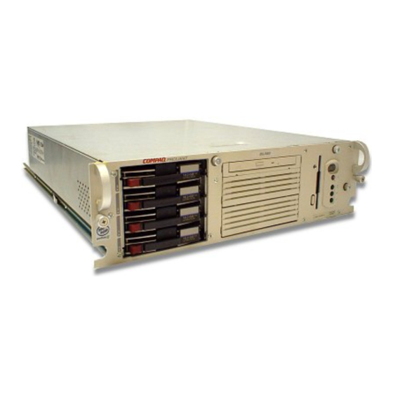
ProLiant DL380 The Compaq ProLiant DL380 server provides the latest processor and system architecture technology, including a 133 MHz front-side bus, hot-plug redundant power supply, error checking and correcting memory, Integrated... - Page 17 1-2 Compaq ProLiant DL380 Setup and Installation Guide This revolutionary combination of features, performance, form factor, and Compaq manageability make this platform unbeatable for file and print management, Web, mail, or small database applications. Figure 1-1. Compaq ProLiant DL380 server...
-
Page 18: Front Panel Components
Front Panel Components The following figure and table show the components on the front panel of the ProLiant DL380 server, including four 1-inch hot-plug drives. Figure 1-2. Identifying components on the front panel of the ProLiant DL380 server Table 1-1... -
Page 19: Thumbscrew Identification
Figure 1-3. Identifying thumbscrew locations on the front bezel Table 1-2 Thumbscrew Locations on the Front Bezel of the ProLiant DL380 Server Number Description... -
Page 20: Rear Panel Components
Rear Panel Components The following figure and table show the components on the rear panel of the ProLiant DL380 server. Figure 1-4. Identifying the rear panel components on the ProLiant DL380 server. Table 1-3 Rear Panel Components for the ProLiant DL380 Server... -
Page 21: Internal Components
The following figure and table illustrate the inside view of the main features of the server. Figure 1-5. Identifying the main internal components for the ProLiant DL380 server NOTE: Heat sink and processor mounting hardware may appear different than illustrated. - Page 22 Server Features 1-7 Table 1-4 Internal Components for the ProLiant DL380 Server Number Internal Components Hot-Plug power supply (275 Watt) Hot-Plug redundant power supply bay (optional power supply) DIMM sockets Processor slot 1 (populated) Processor slot 2 Processor Power Module slot 1 (populated)
-
Page 23: System Board Components
1-8 Compaq ProLiant DL380 Setup and Installation Guide System Board Components The following figure and table illustrate the various components of the system board. Figure 1-6. Identifying system board components Table 1-5 System Board Components Number Component Number Component DIMM sockets... -
Page 24: Industry Support
PCI expansion boards, as well as support for SCSI devices. Standard Features The following features are standard on all Compaq ProLiant DL380 models, unless otherwise noted. Processors and Processor Power Modules One processor and integrated Level 2 cache... -
Page 25: System Memory
Expansion Slots The expansion slots on the riser board are configured as shown. Figure 1-7. Locating ProLiant DL380 expansion slots. These expansion slots on the riser board correspond to slots on the rear of the server. -
Page 26: Disk Controller
Server Features 1-11 Figure 1-8. Rear view of expansion slot locations Slot location 1 is a 32-bit PCI expansion slot. Slots 2, 3, and 4 are 64-bit PCI expansion slots. The 32-bit PCI bus provides data transfer rates of up to 133 MB/s while the 64-bit bus transfers at a rate of up to 266 MB/s. -
Page 27: Integrated Network Controller
For more information about the Integrated Network Controller, refer to the Documentation CD. Mass Storage The Compaq ProLiant DL380 server can house up to eight mass storage devices as shown in the following figure and table. Up to four 1-inch height Compaq hot-plug hard drives A low-profile IDE CD-ROM drive A 3.5-inch, 1.44-MB diskette drive, installed in the vertical position... -
Page 28: Standard Interfaces
Server Features 1-13 Figure 1-9. ProLiant DL380 server drive positions Table 1-6 Media Bays for the ProLiant DL380 Server Number SCSI IDs Configuration 0, 1, 2, 3 Hot-Plug drive cage accommodating four 1-inch height Compaq Wide Ultra2 SCSI hot-plug hard drives A, B Two 5.25-inch wide x half-height drive bays... -
Page 29: Video
1-14 Compaq ProLiant DL380 Setup and Installation Guide Compaq NC3163 Fast Ethernet NIC Embedded 10/100 WOL with autosensing capability on the PCI local bus IDE Interface for Low Profile CD-ROM drive Diskette Drive Connector Interface Video Standard video integration in ProLiant DL380 servers includes: Integrated Video Controller with maximum resolution of 1280 x 1024 non-interlaced resolution at 16.7 M... -
Page 30: Pre-Failure Warranty
Compaq authorized resellers. Under the terms of this warranty, supported components are eligible for replacement before they actually fail provided that you use Compaq Insight Manager and that the system determines that the supported components have degraded below predetermined reliability thresholds within the product warranty period. -
Page 31: Default Configuration
Compaq SmartStart SmartStart, which is located on the SmartStart and Support Software CD, is the intelligent way to configure your Compaq server with major operating system software. SmartStart helps you achieve a well-integrated server that ensures maximum manageability and dependability. For additional information about configuration, see Chapter 6, “Server Configuration and... -
Page 32: Disk Management
Server Features 1-17 Integrated Management Log (IML) provides a detailed log of key system events. This log is accessible through Compaq Insight Manager and the Remote Insight Board. Disk Management Disk management allows the server to recover from a hard drive problem without interrupting the server’s performance. -
Page 33: Automatic Server Recovery-2 (Asr-2)
Automatic Server Recovery-2 (ASR-2) Automatic Server Recovery-2 (ASR-2) enables the server to boot automatically from either the operating system or the Compaq Utilities. If there is a critical system failure, ASR-2 automatically restarts the server and pages a designated system administrator. -
Page 34: Compaq Remote Insight Board (Pci Option)
Server Features 1-19 Compaq Remote Insight Board (PCI Option) The Compaq Remote Insight Board PCI option is a PCI-based, single-board computer that is installed to provide remote management of a server, regardless of the state of the host operating system or the host CPU. - Page 35 1-20 Compaq ProLiant DL380 Setup and Installation Guide Table 1-7 Status LEDs on the Front Panel of the ProLiant DL380 Server Number LED Description Status Power ON/STANDBY Status Amber = STANDBY Green = ON Disk drive activity, Green = Drive Activity...
-
Page 36: Security Features
Server Features 1-21 RJ-45 LED Indicators There are two LED indicators on the RJ-45 connector. The LED on the left indicates NIC Activity 1, where On indicates activity and Off indicates no activity by the server. The LED on the right indicates NIC Link Status 2, where On indicates a good link and Off indicates no link. -
Page 37: Diagnostics
DIMMs purchased from a Compaq authorized reseller. Under the terms of this warranty, supported components are eligible for replacement before they actually fail, provided that you use Compaq Insight Manager and that the system determined that supported components have degraded below predetermined reliability thresholds within the product warranty period. -
Page 38: Installing The Proliant Dl380 Server
Managing server cabling Accessing the internal components of the rack-mounted server You can choose the optional installation service from Compaq to install your rack products. Refer to the “Optional Installation Service” at the end of this chapter for additional information. - Page 39 The Rack Builder Pro Configuration Tool and Rack Products Documentation information can be found on the web on the Compaq website http://www.compaq.com The entire Rack Resource CD Kit ships with all Compaq racks. A summary of the content of each CD follows: Rack Builder Pro Configuration Tool This information allows you to simulate potential Compaq rack configurations based on your input.
-
Page 40: Rack Warnings And Precautions
Rack Information Library This information allows you to view, search, and print documentation for Compaq racks and rack options. It also assists in the setup and optimization of your new Compaq rack to best fit the needs of your environment. -
Page 41: Server Warnings And Precautions
CAUTION: The Compaq ProLiant DL380 Server must always be operated with the system unit cover on. Proper cooling will not be achieved if the system unit... -
Page 42: The Optimum Environment
Installing the ProLiant DL380 Server 2-5 The Optimum Environment When installing your Compaq ProLiant DL380 server in a rack, certain standards of temperature and power requirements must be met. Space Requirements The following spatial needs should be considered when deciding where to... -
Page 43: Grounding Requirements
Airflow Requirements Compaq ProLiant DL380 servers draw cool air in through the front door and exhaust warm air out the rear. Therefore, the front door of the rack must be adequately ventilated to allow ambient room air to enter the cabinet, and the rear door must be adequately ventilated to allow the warm air to escape from the cabinet. -
Page 44: Unpacking The Rack Server
System Configuration Utility), and then boot the server from the SmartStart program. 11. Install Compaq Insight Manager to manage the server. For Compaq Management CD initialization procedures, refer to the Server Setup and Management pack shipped with your server. -
Page 45: Locating Materials
2-8 Compaq ProLiant DL380 Setup and Installation Guide Locating Materials All of the rack mounting hardware needed to install the ProLiant DL380 server into the rack is included with the rack or with the server. Figure 2-2. Rack-mounting hardware Contents of the server box include... -
Page 46: Installing The Proliant Dl380 Server
See Chapter 3, “Installing Hardware Options,” for information on installing PCI expansion boards and other major hardware options. The following major hardware options are available for the ProLiant DL380 server and may be obtained from your local Compaq authorized reseller or... -
Page 47: Preparing The Mounting Brackets And Slide Rail Assemblies
2-10 Compaq ProLiant DL380 Setup and Installation Guide PCI expansion boards Tape drives 2 x 1-inch hot-plug hard drive cage Remote Insight Board Hot-plug, redundant power supply This guide covers only the installation of optional drive cage and hard drives, tape drives, memory, expansion boards, hot-plug redundant power supplies, and a second processor unit. - Page 48 Installing the ProLiant DL380 Server 2-11 Slide Rail Assembly Components Each slide rail assembly attaches to the server and to the rack-mounting bracket. The components of the slide rail assembly include the outer bracket rail, which includes the outer bracket rail 1 and the inner slide 2, and the server rail 3, which attaches to the server.
-
Page 49: Attaching The Outer Bracket Rail To The Rack Mounting Bracket
2-12 Compaq ProLiant DL380 Setup and Installation Guide Attaching the Outer Bracket Rail to the Rack Mounting Bracket 1. Place the two slide rail assemblies, the two rack mounting brackets, and the 4 ¼-in fasteners on a flat surface. 2. Extend the server rail from the outer bracket rail until the server rail release latch clicks 1. - Page 50 Installing the ProLiant DL380 Server 2-13 Figure 2-6. Separated outer bracket rail (top) and server rail The outer bracket rail consists of two parts: a fixed outer rail that attaches to the rack mounting bracket and an inner slide on a steel ball-bearing movement.
- Page 51 2-14 Compaq ProLiant DL380 Setup and Installation Guide Also, the front of the rack-mount bracket can be identified by the round threaded holes; the rear of the rack-mount bracket has oval holes. Figure 2-8. Positioning the rack-mounting bracket for installation of the outer...
- Page 52 Installing the ProLiant DL380 Server 2-15 6. Use one more 8-32 x ¼-inch slotted screw to fasten the outer bracket rail to the rack-mounting bracket 4. See Figure 2-9. 7. Refer to Figure 2-9 and repeat Steps 1 through 4 for the second assembly.
- Page 53 2-16 Compaq ProLiant DL380 Setup and Installation Guide Figure 2-9. Steps for attaching the outer bracket rail to the rack-mounting bracket 12. Tighten the three 8-32 x ¼-inch slotted screws used to fasten the outer bracket rail to the rack-mounting bracket.
-
Page 54: Attaching The Rack Mounting Bracket And Slide Assembly To The Rack
Installing the ProLiant DL380 Server 2-17 Attaching the Rack Mounting Bracket and Slide Assembly to the Rack WARNING: To reduce the risk of personal injury or damage to the equipment, be sure that the rack leveling feet are extended to the floor and support the full weight of the rack. -
Page 55: Inserting Cage Nuts In The Rack Frame
2-18 Compaq ProLiant DL380 Setup and Installation Guide Figure 2-10. Measuring with the template 3. After marking the front of the rack, open the rear door of the rack, flip the template over, and mark the back rails of the rack. -
Page 56: Attaching The Rack Mounting Bracket Assembly To The Rack
Installing the ProLiant DL380 Server 2-19 Figure 2-11. Inserting cage nuts 4. Using the fitting tool as a lever, pry the cage nut into position. 5. Repeat Steps 1 through 4 for each cage nut. Attaching the Rack Mounting Bracket Assembly... - Page 57 2-20 Compaq ProLiant DL380 Setup and Installation Guide Figure 2-12. Attaching rack mounting bracket assembly to the front of the rack (left side) IMPORTANT: Insert only one screw in the front of the bracket and position it in the bottom hole.
- Page 58 Installing the ProLiant DL380 Server 2-21 3. Secure the back end of the mounting bracket assembly to the back corner brace of the rack with one M6 x 1.0-12L Phillips screw through the bottom hole of the left side of the bracket and the cage nut and one screw through the bottom hole of the right side of the bracket and cage nut, as shown.
-
Page 59: Attaching Server Rails To The Server
2-22 Compaq ProLiant DL380 Setup and Installation Guide Attaching Server Rails to the Server 1. Place the center tab on the server rail with the open end of the tab toward the front of the server. IMPORTANT: The server rails attach to the server with the flat side of the rail against the server. -
Page 60: Loading The Rack Server
Installing the ProLiant DL380 Server 2-23 Figure 2-17. Attaching the server bracket to the server Loading the Rack Server Before attaching additional mounting bracket assemblies, follow the steps below to load and secure the server to the rack with the front bezel thumbscrews. - Page 61 2-24 Compaq ProLiant DL380 Setup and Installation Guide 1. Pull the slide rails forward until they are fully extended from the mounting brackets. At full extension, the rails lock into place, as shown in the following figure. Figure 2-18. Extending the rack rails until they lock into place...
- Page 62 Installing the ProLiant DL380 Server 2-25 2. Carefully align the server component rails with the rack slide rails, as shown in the following figure. Figure 2-19. Aligning the server component rails with the rack rails 3. Ensure that the server component rails are fully engaged into the plastic guides and bearings on the rack rails on both sides, then slowly slide the server into the rack.
- Page 63 2-26 Compaq ProLiant DL380 Setup and Installation Guide 4. Press the component rail release latches inward 1 on both sides of the server, and continue to slide the server into the rack. Figure 2-20. Loading the rack server IMPORTANT: The first time you slide the server into the rack, you may have to apply...
-
Page 64: Attaching The Cable Management Arm
Installing the ProLiant DL380 Server 2-27 5. Position the server in the rack, as shown in the following figure. Figure 2-21. Using thumbscrews to secure the positioned server in the rack 6. Secure the server faceplate to the front of the rack by fastening the thumbscrews into the cage nuts. - Page 65 2-28 Compaq ProLiant DL380 Setup and Installation Guide Figure 2-22. Attaching the cable management arm to the cable management arm server bracket 2. The cable management arm attaches to the rack via the cable management arm rack bracket. Align the cable management arm rack bracket to the left side on the rack.
-
Page 66: Connecting The Power Cord And Peripheral Devices
Installing the ProLiant DL380 Server 2-29 3. Align the other end of the cable management arm on the outside of the rack bracket attached to the rack. Attach the arm to the rack bracket with two 10-32 x 5/8-inch Phillips washer-face hex-head screws. - Page 67 2-30 Compaq ProLiant DL380 Setup and Installation Guide Figure 2-25. Rear panel of the ProLiant DL380 server Table 2-1 Rear Panel Connectors/LED on the ProLiant DL380 Server Number Connector or LED External SCSI connector Video connector (blue) RJ-45 Fast Ethernet connector with 10/100-Mbit/s operation, with LED...
- Page 68 Installing the ProLiant DL380 Server 2-31 Use the following procedure to connect the power cord and peripheral cables: 1. Plug cables into the server. Figure 2-26. Cabling through the cable management arm and cable support 2. Plug the power cords into the server. Make a small loop in each power supply cable and secure the loop as a strain relief to the location below the power supply.
-
Page 69: Power Cords
2-32 Compaq ProLiant DL380 Setup and Installation Guide Figure 2-28. Securing cables to the cable management arm 4. Extend the bundled cables down the rack’s cable channel. Before loading additional components, be sure the server is secured to the rack using the front bezel thumbscrews. -
Page 70: Powering Up The Server
Installing the ProLiant DL380 Server 2-33 Powering Up the Server After the cables have been connected to the server, you are ready to power on the ProLiant DL380 server. WARNING: To reduce the risk of electric shock or damage to the equipment: Do not disable the power cord grounding plug. -
Page 71: Configuring The Server With Compaq Smartstart
2-34 Compaq ProLiant DL380 Setup and Installation Guide Configuring the Server with Compaq SmartStart Compaq SmartStart is the intelligent way to configure the server and to load the system software, thereby achieving a well-integrated server to ensure maximum dependability and supportability. The Compaq SmartStart and Support Software CD holds the Compaq System Configuration Utility and ROMPaq. -
Page 72: Using The Power Switch
Server Setup and Management pack to configure the system and load the operating system. To manage the system, refer to the Compaq Management CD provided in the Server Setup and Management pack shipped with your server. -
Page 73: Using Diagnostic Tools
2-36 Compaq ProLiant DL380 Setup and Installation Guide Figure 2-31. Using the power switch Using Diagnostic Tools The software and firmware diagnostic tools available for your use are: Power-On Self-Test (POST) Diagnostics (DIAGS) ROMPaq utilities to upgrade flash ROMs Automatic Server Recovery-2 (ASR-2) -
Page 74: Optional Installation Service
Hardware installation service is available in all countries where Compaq has a direct or indirect service presence. It may be ordered from and directly provided by a Compaq authorized service reseller, or in the United States only, Call 1-800-OK-COMPAQ. In the United States, Compaq will make all of the arrangements to have the rack system installed by qualified Guaranteed Service Providers. -
Page 75: Installing Hardware Options
Chapter Installing Hardware Options This chapter is divided into two major parts: Accessing Non-Hot-Plug (Removable Media) Areas Shut down the server to install media options, upgrades, and replacements: Processor sockets Memory sockets System boards Expansion boards Riser boards and riser board braces Removable media devices Accessing the Hot-Plug Areas Install hot-plug options, upgrades, and replacements without shutting... -
Page 76: Accessing Non-Hot-Plug Areas
3-2 Compaq ProLiant DL380 Setup and Installation Guide Accessing Non-Hot-Plug Areas Move the server Power On/Standby switch to the Standby position and remove the power cord(s) before installing options, upgrades, or replacements. Accessing Processors, Memory Sockets, System Board, and Removable Media Area WARNING: To reduce the risk of personal injury from hot surfaces, allow the internal system components to cool before touching. - Page 77 Installing Hardware Options 3-3 Figure 3-1. Locating thumbscrews on front bezel 6. Pull the server out from the rack. IMPORTANT: It is not necessary to remove the server completely from the rack. 7. On the front of the unit, loosen the three thumbscrews that secure the server access panel.
-
Page 78: Installing A Processor And Processor Power Module
3-4 Compaq ProLiant DL380 Setup and Installation Guide Installing a Processor and Processor Power Module To install a processor on the system board, refer to the label inside the server access panel, refer to the processor option kit, or use the following procedure. - Page 79 Installing Hardware Options 3-5 CAUTION: Processor slot 1 must be populated at all times. Failure to follow this process will result in the system failing to boot and halting during the POST test. This error will result in the system not functioning properly. 1.
-
Page 80: Installing A Processor Power Module
3-6 Compaq ProLiant DL380 Setup and Installation Guide Installing a Processor Power Module Every processor supplied by Compaq comes with a Processor Power Module (DC-to-DC converter). Each PPM must be installed in the slot adjacent to its processor to provide power to that processor. If the processor is installed in slot 1, install the PPM in slot 1. - Page 81 Installing Hardware Options 3-7 4. Push the module into the socket until the socket latches snap into place and secure the PPM. 5. Replace the server access panel. 6. Push the server into the rack, secure with thumbscrews, and reconnect cables.
-
Page 82: Adding Memory To The Proliant Dl380 Server
Adding Memory to the ProLiant DL380 Server You can expand server memory by installing Compaq SDRAM. The system supports up to four 133-MHz registered SDRAM Dual Inline Memory Modules (DIMMs) installed in slots on the system board. Identify the DIMM sockets on the system board. -
Page 83: Maximum Memory Configuration
128279-B21 512-MB option kit 128280-B21 1-GB option kit (when available) CAUTION: Use only Compaq DIMMs. DIMMs from other sources are known to adversely affect data integrity. Maximum Memory Configuration The ProLiant DL380 server allows ultimate expansion to 4-GB (when 1-GB DIMMS become available). -
Page 84: Installing Dimms
3-10 Compaq ProLiant DL380 Setup and Installation Guide Installing DIMMs CAUTION: Electrostatic discharge can damage electronic components. Be sure you are properly grounded before beginning any installation procedure. See Appendix B, “Electrostatic Discharge,” for more information. To install a memory module, complete the following steps: 1. -
Page 85: Removing The Riser Board Shipping Bracket
Installing Hardware Options 3-11 Removing the Riser Board Shipping Bracket Some models of the ProLiant DL380 Server include a bracket to keep expansion boards in place during shipping. You must remove this bracket before installing or removing expansion boards; however, reinstalling the bracket is optional. -
Page 86: Installing An Expansion Board
3-12 Compaq ProLiant DL380 Setup and Installation Guide Figure 3-10. ProLiant DL380 riser board slots Installing an Expansion Board Installing the Board To install an expansion board, refer to the following installation procedure. WARNING: To reduce the risk of personal injury, be careful when installing and removing expansion boards. - Page 87 Installing Hardware Options 3-13 4. Press the top 1 of the expansion slot latch and open the latch toward the rear 2 of the expansion slot cage. Figure 3-11. Opening the expansion slot latch 5. Remove the expansion slot cover 3. Figure 3-12.
- Page 88 3-14 Compaq ProLiant DL380 Setup and Installation Guide 6. Insert the expansion board 4. CAUTION: To avoid the risk of damage to your system or expansion boards, remove all AC power cords before installing or removing expansion boards. With the front panel power switch in the Standby position, auxiliary power is still connected to the PCI expansion slot and may damage the card.
-
Page 89: Replacing The Riser Board And Riser Board Brace
NOTE: Replacing the riser board is optional 1. If the server is on, place it in Standby mode and disconnect the power cords. See to Chapter 2, “Installing the ProLiant DL380 Server.” 2. Remove the server access panel. 3. Remove all expansion boards by reversing the steps in the “Installing an Expansion Board”... - Page 90 Figure 3-15. Installing the riser board and riser board brace 8. Replace all expansion boards. 9. Replace the server access panel. 10. Slide the ProLiant DL380 server into the rack and secure it using the thumbscrews. 11. Reconnect all cabling and turn the server on.
-
Page 91: Installing Hardware Options
Ultra2 SCSI drives for a total of six hot-plug drives on a single channel. Other SCSI devices can be installed in removable media bays 4 and 5. These bays are 5.25 inches wide x 1.6 inches high. CAUTION: The ProLiant DL380 server does not support the installation of IDE or EIDE fixed disk drives. -
Page 92: Replacing The 1.44-Mb Diskette Drive
3-18 Compaq ProLiant DL380 Setup and Installation Guide Figure 3-16. Mass storage device placement for ProLiant DL380 with two drives installed in 2 x 1-inch optional drive cage. Replacing the 1.44-MB Diskette Drive Removing the 1.44-MB Diskette Drive 1. If the server is on, place it in Standby mode and disconnect the power cord(s). - Page 93 Installing Hardware Options 3-19 4. Disconnect the cabling to the 1.44-MB diskette drive. Figure 3-17. Disconnecting the 1.44-MB diskette drive cabling 5. Remove the T-15 Torx screw 1 and slide the diskette drive away from front bezel as directed by the bottom guide screws 2. Figure 3-18.
-
Page 94: Installing External Storage Devices
To install the 1.44-MB diskette drive into the server, reverse the steps noted in the preceding procedure. Installing External Storage Devices Optional mass storage devices can be connected to the Compaq ProLiant DL380 server by using the external SCSI port on the back of the unit. -
Page 95: Installing A Half-Height Device
Installing Hardware Options 3-21 Installing a Half-Height Device Install a half-height removable media device into the removable media bay area: 1. To gain access to the screws securing the removable media trays, remove the diskette drive by following the steps in “Removing the 1.44-MB Diskette Drive.”... - Page 96 3-22 Compaq ProLiant DL380 Setup and Installation Guide 3. Insert the half-height device into the removable media bay 3 and secure it to the chassis using a T-15 Torx screw 4. Figure 3-21. Installing a half-height device 4. Connect the two device terminated SCSI cable to the half-height device.
-
Page 97: Installing A Full-Height Device (Dlt Tape Drive)
Installing Hardware Options 3-23 5. Replace the 1.44-MB diskette drive. 6. Replace the server access panel. 7. Push the server into the rack and secure with thumbscrews. 8. Reconnect the power cord and power on the server. 9. Reconfigure the server. See Chapter 6, “Server Configuration and Utilities,”... - Page 98 3-24 Compaq ProLiant DL380 Setup and Installation Guide Insert the Digital Linear Tape (DLT) tape drive into the removable media bay area 1, and secure it to the bottom of the unit with four T-15 Torx screws 2. Figure 3-24. Installing a DLT tape drive into the removable media cage 3.
- Page 99 Cage Option Installing the optional Wide Ultra2 SCSI drive cage allows you use up to two additional 1-inch hot-plug Wide Ultra2 drives in your ProLiant DL380 server. The standard Integrated Smart Array Controller in your server supports the drive cage and additional hot-plug drives.
- Page 100 3-26 Compaq ProLiant DL380 Setup and Installation Guide 5. Install the drive cage 1 and secure the cage to the chassis with the access screws 2. Figure 3-27. Securing the 2 x 1-inch Ultra2 SCSI drive cage 6. Attach the power cable to the power connector 3 on the new drive cage.
- Page 101 Installing Hardware Options 3-27 8. Install the point-to-point SCSI cable, provided in the option kit, between the 2 x 1-inch drive cage 5 and the 4 x 1-inch drive cage 6. Figure 3-29. Installing the point-to-point SCSI cable (provided in the 2 x 1-inch drive cage option kit) 9.
-
Page 102: Enabling The Power Switch Security Feature
3-28 Compaq ProLiant DL380 Setup and Installation Guide NOTE: Because the ProLiant DL380 server features an Integrated Smart Array Controller, you do not need to connect or configure additional SCSI controllers. The Wide Ultra2 SCSI drive cage option is now installed in your server. Install Wide Ultra2 SCSI hard drives in the drive cage 1, 2 and restore data from your data backup onto the new drives, as needed. - Page 103 Installing Hardware Options 3-29 2. Remove the server access panel. 3. Remove the 1.44-MB diskette drive. See “Replacing the 1.44-MB Diskette Drive” for details. 4. Use a narrow instrument to release each clip from the bezel 1 and 2 by pushing inward slightly, as shown in the following figure.
-
Page 104: Replacing The Cd-Rom Drive
1. If the server is on, place it in Standby mode and disconnect the power cord(s). See Chapter 2, “Installing the ProLiant DL380 Server.” 2. Pull the server forward in the rack for access to the inside of the server. - Page 105 Installing Hardware Options 3-31 6. Remove the screw that secures the CD-ROM tray assembly to the chassis 2. 7. Slide the CD-ROM tray forward out of the server 3. Figure 3-34. Removing the CD-ROM drive from the chassis Installing the CD-ROM Drive To install the CD-ROM drive, reverse the steps in the preceding procedure.
- Page 106 Bays 4 and 5 can accommodate two half-height or one full-height devices. Devices that can be installed include an additional CD-ROM drive, 2 x 1-inch Wide Ultra2 SCSI drive cage, or SLR, DAT, AIT or DLT tape drives. A detailed list of supported options is available at the Compaq website http://www.compaq.com...
-
Page 107: Accessing Hot-Plug Areas
Installing Hardware Options 3-33 Accessing Hot-Plug Areas This section describes accessing the following areas: Hot-plug Wide Ultra2 SCSI drives Hot-plug power supplies Installing Hot-Plug Wide Ultra2 SCSI Drives 1. Remove the blank from the hot-plug hard drive cage. 2. Insert the hot-plug drive 1. 3. -
Page 108: Scsi Id Numbers For Wide Ultra2 Scsi Models
3-34 Compaq ProLiant DL380 Setup and Installation Guide SCSI ID Numbers for Wide Ultra2 SCSI Models The ProLiant DL380 configuration consists of four 1-inch hot-plug drives 1 numbered SCSI ID 0, 1, 2, and 3. The trays in the removable media area 2 can be removed and the optional 2 x 1-inch drive cage installed to accommodate two additional Wide Ultra2 SCSI hard drives. -
Page 109: Installing A Hot-Plug Redundant Power Supply
Installing Hardware Options 3-35 Installing a Hot-Plug Redundant Power Supply CAUTION: This server only supports 275-watt hot-plug power supplies. You can differentiate the power supply by the key on the bottom of the power supply. Figure 3-38. 275-watt hot-plug power supply 1. - Page 110 3-36 Compaq ProLiant DL380 Setup and Installation Guide 2. Open the lever on the cable management arm 1 and swing the arm out of the way 2. Figure 3-39. Accessing the hot-plug power supplies 3. Remove the hot-plug power supply blank as shown in the following figure.
- Page 111 Installing Hardware Options 3-37 4. Open the power supply latch on the new supply by pressing the thumb release and opening the latch. Install the new hot-plug power supply in your open area. Push the hot-plug power supply into the slot 1 and swing the arm into the locking position 2.
- Page 112 3-38 Compaq ProLiant DL380 Setup and Installation Guide 6. Secure the power supply cord by fastening it to the clamp on the power supply and attach to the cable management arm. Figure 3-43. Securing the power cord 7. Swing the cable management arm back into place 1 and secure the latch 2.
-
Page 113: Integrated Smart Array Controller
Chapter Integrated Smart Array Controller This chapter provides an overview of the ProLiant DL380 server Integrated Smart Array Controller. Features The ProLiant DL380 Integrated Smart Array Controller is a dual channel Ultra2 SCSI array controller. Both channels support Low Voltage Differential (LVD) SCSI devices. -
Page 114: Scsi Ports
4-2 Compaq ProLiant DL380 Setup and Installation Guide Option ROM Configuration for Arrays Pre-Failure Notification and Pre-Failure Warranty through Compaq Insight Manager Performance monitoring through Compaq Insight Manager SCSI Ports SCSI Port 2 is dedicated to controlling the SCSI drives in the internal drive bay. -
Page 115: Array Configuration
Integrated Smart Array Controller. Back up all data before migrating a drive from a non-intelligent controller to an intelligent array configuration. NOTE: See the Compaq Integrated Smart Array Controller User Guide for further information about the Integrated Smart Array Controller. -
Page 116: Cabling Guidelines
Chapter Cabling Guidelines This chapter is intended to help you set up your server and drive cage options for optimal performance. Use this chapter along with the technical information on the Quick Hardware Installation Poster and the labels found on the inside of the server access panel for complete and comprehensive information. - Page 117 5-2 Compaq ProLiant DL380 Setup and Installation Guide WARNING: To reduce risk of electrical shock, fire, or damage to the equipment, do not plug telephone or telecommunications connectors into the RJ-45 receptacle. WARNING: To reduce the risk of electric shock or damage to the equipment: Do not disable the power cord grounding plug.
-
Page 118: Rear Panel Connectors
Cabling Guidelines 5-3 Rear Panel Connectors The following figure and table show the connectors and switches for the ProLiant DL380 server. Figure 5-1. Location of rear panel connectors Table 5-1 Rear Panel Connectors Number Connector External SCSI connector Video connector (blue) -
Page 119: Internal Connectors
5-4 Compaq ProLiant DL380 Setup and Installation Guide Table 5-1 Rear Panel Connectors continued Number Connector Standard hot-plug power supply, with LED External SCSI access < Expansion slots Internal Connectors The main connectors are the two SCSI Ports (Port 1 and Port 2), the diskette drive connector, and the CD-ROM connector. -
Page 120: Cabling The Server's Rear Panel Cables
Cabling Guidelines 5-5 Table 5-2 Important Connectors Number Connector CD-ROM connector Diskette drive connector Port 2 SCSI connector, connect to the hot-plug drive cage Port 1 SCSI connector, connects to the removable media bay for SCSI NOTE: If you are connecting an external SCSI device through the external SCSI connector on the rear of the server you must disconnect the cable from port 1. - Page 121 5-6 Compaq ProLiant DL380 Setup and Installation Guide 2. Plug in the hot-plug power supply cables as shown. Figure 5-4. Securing the hot-plug power supply cables 3. Bundle all of the cables, including the power cables, and tie them to the cable management arm.
-
Page 122: Additional Mass Storage Devices
Compaq SCSI cables for the ProLiant DL380 server are terminated. Be sure to remove all terminating jumpers from third-party SCSI devices. Supported Compaq SCSI options are not terminated. Completing the Installation Process Use the Compaq SmartStart and Support Software CD and set up your new configuration. -
Page 123: Proliant Dl380 Server Cable Kit Contents
Configuration Utility. Run the System Configuration Utility after you install an option in your ProLiant DL380 server. ProLiant DL380 Server Cable Kit Contents All cabling for ProLiant DL380 models is illustrated in the following figure and table. Before beginning the installation process, verify that you have the four cables shipped with your server. - Page 124 This adapter is included in all Compaq option kits containing narrow devices. To order the 50-68 pin adapter for use with any third-party option, order Option Kit (Part Number 212055-001) through your local Compaq authorized reseller or Compaq authorized service provider.
-
Page 125: Scsi Cable Connectors
5-10 Compaq ProLiant DL380 Setup and Installation Guide SCSI Cable Connectors To help identify the SCSI cables required for ProLiant DL380 server installation, refer to the connectors illustrated in the following figure. SCSI cables have the following characteristics: External SCSI cables have a round wire with securable connectors. -
Page 126: Scsi Cabling Guidelines
Refer to the following tables to determine the parts that are necessary for successful cabling of the ProLiant DL380 server. To customize the cabling needs of your Compaq ProLiant DL380 server to your specific application, use the following procedure: 1. Determine whether the cabling needs are internal or external. -
Page 127: Internal Scsi Cabling Guide For Proliant Dl380 Servers
5-12 Compaq ProLiant DL380 Setup and Installation Guide Internal SCSI Cabling Guide for ProLiant DL380 Servers The ProLiant DL380 server includes the following cabling components: One CD-ROM cable One diskette drive cable One two-device terminated SCSI cable One point-to-point SCSI cable... -
Page 128: Internal Cabling
Cabling Guidelines 5-13 Internal Cabling Table 5-4 Internal Cabling for the Compaq ProLiant DL380 Server Compaq DAT drive, SLR Wide Ultra2 SCSI Wide Ultra2 SCSI ProLiant DL380 drive, DLT drive, hot-plug hard hot-plug hard AIT drive drives drive (in standard... -
Page 129: External Cabling
5-14 Compaq ProLiant DL380 Setup and Installation Guide External Cabling IMPORTANT: SCSI devices can NOT be supported on the external SCSI port and the internal SCSI port 1, concurrently. External Cabling for Primary Storage Only Table 5-5 External Cabling for Primary Storage Only... -
Page 130: External Cabling For Secondary Storage
ProLiant DL380 Cabling Examples The following examples illustrate cabling scenarios associated with a ProLiant DL380 server. They are provided as only an overview for installing and routing some of the cabling scenarios described in the SCSI Cable Usage Table. Refer to the labels attached to the inside of the system unit access panel for additional information. - Page 131 5-16 Compaq ProLiant DL380 Setup and Installation Guide Connecting an Array Controller to the Hot-Plug Drive Cage Backplane Board Disconnect the point-to-point SCSI cable from Port 2 on the system board and attach it to the Array Controller to connect the Controller to the hot-plug drive cage as shown in the following figure.
- Page 132 Cabling Guidelines 5-17 Cabling a DLT drive to SCSI Port 1 The following figure shows an example of cabling a DLT drive to SCSI port 1. Figure 5-9. Cabling a DLT drive to port 1 NOTE: Heat sink and processor mounting hardware may appear different than illustrated. Cabling a Half-Height Tape Drive SCSI Port 1 The following figure shows an example of cabling a DLT drive to SCSI port 1.
-
Page 133: Proliant Dl380 Maximum External Storage Cabling
Connecting Four Array Controllers for Maximum External Storage Capacity The ProLiant DL380 server will support four array controllers for maximum external storage capability. Supported array controllers have external ports on the rear of the controller to allow rear server access to all available controller... -
Page 134: Server Configuration And Utilities
Chapter Server Configuration and Utilities This chapter provides many configuration options including instructions for using the Compaq System Configuration Utility and Compaq SmartStart, and for loading device drivers. System Configuration Utility The Compaq System Configuration Utility performs a wide range of... -
Page 135: Resolving Resource Conflicts
If the SmartStart and Support Software CD is used the first time the server is configured, the SmartStart program automatically creates a system partition and installs the System Configuration Utility and other Compaq utilities in that partition. IMPORTANT: This Compaq system utilities partition should not be confused with the partitions created by your operating system. -
Page 136: Starting The System Configuration Utility
The first time you start the Compaq System Configuration Utility, follow the procedure on the Compaq SmartStart Installation poster. After the Compaq SmartStart and Support Software CD is used for the first time to create and populate the Compaq system partition, you may access the System Configuration Utility as follows: 1. -
Page 137: Verifying The System Partition
1. Insert the Compaq SmartStart and Support Software CD in the CD-ROM drive and turn on the computer. 2. Select Upgrade System Partition. 3. Select the option to upgrade the utilities. Compaq SmartStart copies the new utilities from the CD to the system partition. System Configuration Utility Main Menu This overview of the main menu options explains how to access the main menu and how to set the power-on features. -
Page 138: System Configuration Menu
Server Configuration and Utilities 6-5 Diagnostics and Utilities –Tests and inspects the computer. Exit from this Utility – Restarts the computer. System Configuration Menu The following options are available from the System Configuration Utility menu: Hardware configuration Drive array configuration Power-on defaults System partition Configuration backup... -
Page 139: System Partition
Use this step to save the configuration update after you have made changes. Drive Array Configuration This option runs the Compaq Array Configuration Utility. This utility allows you to view and make changes to your array controller’s configuration. Power-On Defaults You can set and change the Power-On features at any time. -
Page 140: Configuration Backup
Server Configuration and Utilities 6-7 Configuration Backup The Configuration Backup option allows you to create a backup of the system configuration and to restore the system configuration from the backup. The following menu options are available: Backup Restore Configuration Backup and Configuration History Files When you save and exit the System Configuration Utility, the utility retains a history of the configuration. -
Page 141: Configuring Pci Boards Automatically
Installing an Operating System Single Processor Operating Support Compaq ProLiant DL380 servers support the following operating systems: Novell NetWare 3.2, 4.2, and 5. NetWare for Small Business 4.2 and 5.0 Microsoft Windows NT Server 3.51, 4.0 Microsoft NT Enterprise 4.0... -
Page 142: Smp Operating System Support
IBM OS/2 Warp Server for E-Commerce Sun Solaris 2.6 and 7 Intel Platform Edition If you use Compaq SmartStart to install the OS, the drivers are installed automatically. When you select the Operating System Installation feature from the System Configuration Utility main menu, the utility provides prompts to simplify the installation. -
Page 143: Loading Compaq Device Drivers
6-10 Compaq ProLiant DL380 Setup and Installation Guide Loading Compaq Device Drivers Compaq device drivers are located on the Compaq SmartStart and Support Software CD. They are also available for download from the Compaq website http://www.compaq.com IMPORTANT: Always check README files on Compaq SmartStart or any Software Support Diskettes or CDs. -
Page 144: Microsoft Windows Nt Device Drivers From Compaq
For more information on driver installation, run the README.BAT file in the root directory of the SSD for Microsoft Windows NT. This action will load the WinHelp file NTREADME.HLP. Compaq SmartStart Installation If you use Compaq SmartStart to install the OS, the drivers are installed automatically. -
Page 145: Sco Openserver And Sco Unixware Device Drivers From Compaq
Device Drivers from Compaq If you are using the Compaq NC3163 Fast Ethernet NIC Embedded 10/100 WOL on a ProLiant DL380 server and you do not plan to use the SmartStart installation process to set up your server, you must install updated support software for your controller to connect properly to the network. - Page 146 One of the diskettes on the Compaq EFS contains a bootable documentation diskette. Before attempting to install the SCO UNIX software, run this diskette and read the README file for the Compaq EFS. It instructs you on how to use the BTLD or HBA diskettes along with the SCO installation media.
- Page 147 One of the diskettes on the Compaq EFS contains a bootable documentation diskette. Before attempting to install the SCO UNIX software, boot this diskette and read the README file for the Compaq EFS. It will instruct you on how to use the BTLD or HBA diskettes along with the SCO installation media.
-
Page 148: Ibm Os/2 Device Drivers From Compaq
IBM OS/2 Device Drivers from Compaq If you are using the Compaq NC3163 Fast Ethernet NIC Embedded 10/100 WOL in a ProLiant DL380 server and you do not plan to use the SmartStart installation process to setup your server, you must install updated support software for your controller to connect properly to the network. - Page 149 6-16 Compaq ProLiant DL380 Setup and Installation Guide 6. Insert the Compaq SmartStart and Support Software CD into the CD drive of a system running Microsoft Windows 95 or Microsoft Windows NT 4.0. 7. In the diskette builder software selection screen, choose Compaq IBM OS/2 NIC Support Software and Compaq IBM OS/2 Support Software (SSD).
-
Page 150: Sunsolaris Device Drivers From Compaq
Banyan VINES operating system. Compaq provides driver support for Banyan VINES 7.x and later versions. These drivers are located on the Compaq SmartStart and Support Software CD you received with your server. You can use SmartStart to create a Banyan VINES Support Software Diskette (SSD) from Compaq to support a manual installation of Banyan VINES. -
Page 151: Diagnostics And Other Utilities
6-18 Compaq ProLiant DL380 Setup and Installation Guide Manual Installation 1. Insert the Compaq SmartStart and Support Software CD into the drive. 2. Boot your system. 3. Select Manual Installation. 4. Follow the instructions that display on the monitor. Diagnostics and Other Utilities... - Page 152 Server Configuration and Utilities 6-19 Controller Naming Conventions For your convenience, some of the popular operating systems, including Microsoft DOS and Novell NetWare products, and corresponding driver names are listed in the following table. Table 6-2 Controller Driver Naming Conventions Operating System Driver Type Driver File Name...
- Page 153 6-20 Compaq ProLiant DL380 Setup and Installation Guide Table 6-2 Controller Driver Naming Conventions continued Operating System Driver Type Driver File Name SCO OpenServer 5 Cnet/cet SCO UnixWare 7 Cnet/cet, n100, n1000c SCO UnixWare 2.1.x DLPI Cnet/cet, n100, n1000c SCO Open Server 3...
-
Page 154: Integrated Management Log
System-dependent drivers. Refer to the Compaq SmartStart and Support Software CD for instructions on installing the appropriate drivers. Viewing the Log You can view an event in the Compaq Integrated Management Log in several ways, including: From within the Compaq Insight Manager... -
Page 155: Compaq Insight Manager
By being able to view the events that may occur to these components, you can take immediate action. You can view and print the event list from within Compaq Insight Manager by following the instructions below. You can also mark a critical or caution event as repaired after the affected component has been replaced. -
Page 156: List Of Events
Integrated Management Log 7-3 the Compaq website. Refer to the Compaq Management CD for information on installing and running the Survey Utility. After you have run the Survey Utility, you can view the IML by loading the output of the utility (typically called SURVEY.TXT) into a text viewer such as Microsoft Notepad. - Page 157 7-4 Compaq ProLiant DL380 Setup and Installation Guide Table 7-1 Event Messages continued Event Type Event Message Uncorrectable Error Uncorrectable Memory Error (Slot X, Memory Module X) Uncorrectable Memory Error (System Memory) Uncorrectable Memory Error (Module Unknown) Processor Correctable Error Threshold exceeded...
-
Page 158: Regulatory Compliance Notices
Numbers For the purpose of regulatory compliance certifications and identification, your ProLiant DL380 server is assigned a Compaq Series Number. The Compaq series number for this product is Series ES1009. The series number can be found on the product label, along with the required approval markings and information. -
Page 159: Class A Equipment
A-2 Compaq ProLiant DL380 Setup and Installation Guide in both classes to bear a label indicating the interference potential of the device as well as additional operating instructions for the user. The rating label on the device shows which class (A or B) the equipment falls into. -
Page 160: Modifications
Regulatory Compliance Notices A-3 Modifications The FCC requires the user to be notified that any changes or modifications made to this device that are not expressly approved by Compaq Computer Corporation may void the user's authority to operate the equipment. Cables... -
Page 161: Canadian Notice (Avis Canadien
A-4 Compaq ProLiant DL380 Setup and Installation Guide Canadian Notice (Avis Canadien) Class A Equipment This Class A digital apparatus meets all requirements of the Canadian Interference-Causing Equipment Regulations. Cet appareil numérique de la classe A respecte toutes les exigences du Règlement sur le matériel brouilleur du Canada. -
Page 162: Japanese Notice
Regulatory Compliance Notices A-5 Japanese Notice Taiwanese Notice Chinese Notice... -
Page 163: Laser Devices
A-6 Compaq ProLiant DL380 Setup and Installation Guide Laser Devices All Compaq systems equipped with a laser device comply with safety standards, including International Electrotechnical Commission (IEC) 825. With specific regard to the laser, the equipment complies with laser product performance standards set by government agencies as a Class 1 laser product. -
Page 164: Laser Product Label
Regulatory Compliance Notices A-7 Laser Product Label The following label or equivalent is located on the surface of the Compaq supplied laser device. This label indicates that the product is classified as a CLASS 1 LASER PRODUCT. This label appears on a laser device installed in your product. -
Page 165: Battery Replacement Notice
Your computer is provided with an internal lithium battery or battery pack. There is a danger of explosion and risk of personal injury if the battery is incorrectly replaced or mistreated. Replacement is to be done by a Compaq authorized service provider using the Compaq spare designated for this product. -
Page 166: Electrostatic Discharge
Appendix Electrostatic Discharge To prevent damaging the system, be aware of the precautions you need to follow when setting up the system or handling parts. A discharge of static electricity from a finger or other conductor may damage system boards or other static-sensitive devices. -
Page 167: Grounding Methods
B-2 Compaq ProLiant DL380 Setup and Installation Guide Grounding Methods There are several methods for grounding. Use one or more of the following methods when handling or installing electrostatic-sensitive parts: Use a wrist strap connected by a ground cord to a grounded workstation or computer chassis. -
Page 168: Installing A New Battery
When your server no longer automatically displays the correct date and time, you may need to replace the battery that provides power to the real-time clock. Under normal use, battery life is usually about five to ten years. Use a Compaq 540-milliampere lithium, 3-volt replacement battery (P/N 179322-001). -
Page 169: Installing The System Board Battery
To install the new battery, complete the following steps: 1. If the server is on, place it in standby mode and disconnect the power. Refer to Chapter 2, “Installing the ProLiant DL380 Server,” for detailed instructions on preparing the server for installation or upgrade. - Page 170 Installing a New Battery C-3 Figure C-2. Inserting new battery 7. Replace the cover and power cord. WARNING: To reduce the risk of electric shock or damage to the equipment: Do not disable the power cord grounding plug. The grounding plug is an important safety feature.
-
Page 171: Switches And Jumpers
System Configuration Utility. Setting System Board Switches The Compaq ProLiant DL380 server has two switch banks (1 and 2) located on the system board that are used to set the overall configuration of your server. -
Page 172: Processor Configuration Switch Settings (Sw1 Settings
Diskette Drive Override Password Disable Maintenance NIC Operating Mode ProLiant DL380 servers come standard with the NC3163 Fast Ethernet Embedded 10/100 WOL network interface controller (NIC). The controller automatically differentiates between the 10-Mbit and 100-Mbit environments when the RJ-45 connector is used. -
Page 173: Scsi Device Jumper Settings
The SCSI ID is set by jumpers ID 2, ID 1, and ID 0 located on each SCSI device. The table below provides the SCSI ID jumper settings for Compaq SCSI hard drives. Table D-2... - Page 174 Appendix Specifications and Connector Interfaces This appendix provides operating and performance specifications for the Compaq ProLiant DL380 components. For other specifications, refer to the Documentation CD. ProLiant DL380 Specifications Table E-1 ProLiant DL380 Specifications Dimensions Height 5.1 in 12.9 cm Depth 22.1 in...
-
Page 175: Connector Interfaces
E-2 Compaq ProLiant DL380 Setup and Installation Guide Table E-1 ProLiant DL380 Specifications continued Rated Input Current 4.8 A (110V) per power 2.4A (220V) supply Rated Input Power 432 W 432 W BTU/HR 1475 1475 Power Supply Output Power Rated Steady-State Power... - Page 176 Specifications and Connector Interfaces E-3 RJ-45 Network Connector There are two LED indicators on the RJ-45 connector. The LED on the left indicates NIC activity 1 and the LED on the right indicates NIC link status 2. Figure E-1. RJ-45 LED Indicators...
- Page 177 Index illustrated 2-23 server rails to the server 2-22 illustrated 2-22 100TX Ethernet rate 1-12 authorized service providers 2-37 10BaseT rate 1-12 Automatic Server Recovery-2 1-16 accessing backup configuration 6-7 hot-plug areas 3-33 Banyan VINES 6-17 hot-plug power supplies 3-36 batteries 1-8 airflow requirements for racks 2-6 part number C-1...
- Page 178 2 Compaq ProLiant DL380 Setup and Installation Guide cable management arm rack Compaq Management CD 2-35 bracket 2-9 Compaq Survey Utility 7-2 installation illustrated 2-28 Compaq System Configuration cabling Utility 2-34 4 position terminated SCSI Compaq TechNotes 1-9 cable 5-8...
- Page 179 Index 3 device drivers electrostatic discharge (ESD) B-1 Banyan VINES 6-17 obtaining additional IBM OS/2 6-15 information B-2 Microsoft Windows NT 6-10 precautions B-1 Novell NetWare 6-10, 6-12, preventing B-1 6-14 storing products B-1 Sunsoft Solaris 6-17 transporting products B-1 Windows NT 6-11, 6-12 types of damage from B-1 diagnostics 2-36, 6-18...
- Page 180 4 Compaq ProLiant DL380 Setup and Installation Guide full-height tape drive See tape drive IBM OS/2 device drivers 6-15 IDE connector illustrated 5-5 IMD See Integrated Management getting help See also help Display grounding IML See Integrated Management methods B-2...
- Page 181 Insight link status 1-20 Manager 7-2 system power status 1-20 severity levels 7-1 loading viewing from Insight Compaq device drivers 6-10 Manager 7-2 operating system 2-35 viewing the log 7-1 rack server 2-23, 2-26 viewing using Survey locating...
- Page 182 6 Compaq ProLiant DL380 Setup and Installation Guide module sockets, illustrated 1-7 Pre-Failure Warranty 1-23 parallel connector 2-30, 5-3 system DIMMS 1-13 partition system expandability 1-10 upgrading 6-4 Microsoft Windows NT device using system partition drivers 6-11 utility 6-6 mounting bracket...
- Page 183 Index 7 power-on cabling 2-31 password security 1-22 safety 2-23 setting defaults 6-6 site planning 2-2 Pre-Failure Warranty 1-14, 1-23 slide rail assembly 2-10, 2-12 preparing slide rail space requirements 2-5 assemblies 2-10 stabilization 2-3 preparing the rack mounting template for server mounting brackets 2-10 brackets 2-17 processor...
- Page 184 8 Compaq ProLiant DL380 Setup and Installation Guide Remote Insight Board 1-19 SCSI connectors removable illustrated 5-4 media bays 1-3 SCSI devices 5-7 media devices SCSI hard drives (installation) 3-17 installation 3-33 media tray 3-21 SCSI IDs removing overview 3-34...
- Page 185 32-MB DRAM installed 1-13 components, illustrated 2-11 Automatic Server Recovery-2 illustrated 2-10, 2-11 (ASR-2) 1-18 preparing 2-10 cache memory 1-10 rack 2-10 Compaq Insight rack server 2-12 Manager 1-17 slots drive positions 5-7 expansion, locating on riser expansion slots 1-10 board 3-11...
- Page 186 10 Compaq ProLiant DL380 Setup and Installation Guide system board, battery unpacking 2-7 replacement C-1 utilities 6-18 configuration utility 6-1 configuration utilities 2-34 memory 1-10 Diagnostics 6-18 partition 6-6 EISA Configuration upgrading 6-4 Utility 2-7 verifying 6-4 INSPECT Utility 2-34...
Need help?
Do you have a question about the ProLiant DL380 and is the answer not in the manual?
Questions and answers