Digital-Ally DVM-800 Operation Manual
Professional vehicle digital video system
Hide thumbs
Also See for DVM-800:
- Installation manual (27 pages) ,
- Operation and installation manual (27 pages) ,
- Operation manual (56 pages)
Table of Contents
Advertisement
860-00186-00 Rev J
DVM-800
Operation Guide
Professional Vehicle Digital Video System
Copyright © 2013-2016, Digital Ally, Inc. All Rights Reserved. This publication may not be reproduced, stored in a retrieval
system, or transmitted in whole or part in any form or by any means electronic, mechanical, recording, photocopying, or in
any other manner without the prior written approval of Digital Ally, Inc.
Advertisement
Table of Contents
Troubleshooting

Related Manuals for Digital-Ally DVM-800


Summary of Contents for Digital-Ally DVM-800
- Page 1 Professional Vehicle Digital Video System Copyright © 2013-2016, Digital Ally, Inc. All Rights Reserved. This publication may not be reproduced, stored in a retrieval system, or transmitted in whole or part in any form or by any means electronic, mechanical, recording, photocopying, or in...
-
Page 2: Table Of Contents
Section - 2: DVM Configuration Overview ......................2-1 Section - 3: Device Configuration ..........................3-1 3.1 Default Configuration ................................3-1 3.2 Using VuVault to Configure your DVM-800 ........................3-1 3.3 General ......................................3-3 Location ........................................3-3 Display .......................................... 3-4 Power ..........................................3-5 Complete Vehicle Power Loss ................................ - Page 3 10.4 Troubleshooting ..................................10-3 10.5 DVM Error Messages................................10-5 10.6 Performing a Reset ................................10-5 10.7 Product Repair ..................................10-5 10.8 Warranty Information ................................. 10-6 10.9 FCC Notice....................................10-7 Section - 11: Contact Information..........................11-1 Digital Ally Inc.| Introduction to the DVM-800 System...
-
Page 4: Introduction To The Dvm-800 System
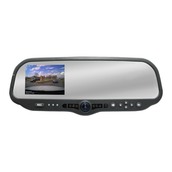
860-00186-00 Rev J Section - 1: Introduction to the DVM-800 System 1.1 Overview of Features DVM-800 Video System Features: Two cameras built into the rear view mirror (One forward road facing, and one passenger facing with IR illumination) ... -
Page 5: Dvm Features Diagram
Used to perform a hard reset of the system Integrated road facing camera: Records the view in front of the vehicle External Audio Input: The DWM Wireless Microphone audio cable is connected here Digital Ally Inc.| Introduction to the DVM-800 System... -
Page 6: Section - 2: Dvm Configuration Overview
860-00186-00 Rev J Section - 2: DVM Configuration Overview Many customizable features are available for the DVM-800. The file that is used to update the DVM configuration is named “deviceconfig”. This file contains all of the necessary wireless settings, operational settings, and user logins. -
Page 7: Section - 3: Device Configuration
However, many parameters can be configured and saved as an activation file. The activation file is saved to a local hard drive or external SD card. The DVM-800 is activated and configured using Digital Ally’s VuVault™ back-office software. Use the VuVault Installation Guide to install the VuVault software. Once installed, follow the instructions in this section to configure and activate your DVM. - Page 8 This will not have any effect on the WTM Settings for wireless connectivity located in the Data Transfer screen. Digital Ally Inc.| Device Configuration...
-
Page 9: General
Local Time Zone. If this is disabled, time will not be adjusted for Daylight Saving. Settings: No, Yes [default] Time Format This time format allows the DVM-800 to be configured in a 12-hour format or a 24-hour format. Settings: 24 Hour, 12 Hour [default] Digital Ally Inc.| Device Configuration... -
Page 10: Display
This LCD behavior can be overridden for external sensors such as the light bar or reverse gear. LCD overrides for connected external sensors are configured separately in the IF box input sensors section. Digital Ally Inc.| Device Configuration... -
Page 11: Power
5 days without discharging the battery. The vehicle’s battery current rating, battery age, and other equipment that remains powered on when the vehicle ignition is off will affect the maximum consecutive days the DVM should remain in Low Power Standby. The following table Digital Ally Inc.| Device Configuration... -
Page 12: Complete Vehicle Power Loss
DVM will power down after 60 seconds using the internal backup battery. External cameras on the DVM-800 rely on the vehicle power supply. Thus, during a complete vehicle power loss to the DVM system, no video can be captured from the external cameras. -
Page 13: Profile
Age parameters are predetermined and can be enabled or disabled. Settings: Enabled, Disabled [default] Gender Profile Gender parameters are predetermined and can be enabled or disabled. Settings: Enabled, Disabled [default] Figure 3-7: DVM Device User prompts if Profile setting is “Enable” Digital Ally Inc.| Device Configuration... -
Page 14: Record
This section defines how the DVM will record audio and video events to the storage media. Recording Details Your DVM-800 includes an external 32GB SD card which is normally used as the primary memory storage. Use the following options in this section to configure your record settings. - Page 15 A setting of “0 second” disables the pre-event function and removes the pre-event audio setting from the Event Audio dropdown menu. Settings: 6, 12, 18, 24, 30 seconds [default] Digital Ally Inc.| Device Configuration...
- Page 16 860-00186-00 Rev J Record Mode In addition to the external SD Card, the DVM-800 has 32GB of internal memory which is permanently installed in the unit. Select one of the following three modes to determine how the storage memory is utilized.
-
Page 17: Cameras
If set to AUTO, an ambient light sensor located on the front of the DVM automatically turns on the IR LED’s during low light conditions. Choose OFF to disable the IR LED’s. Settings: Off, Auto [default] Digital Ally Inc.| Device Configuration 3-11... -
Page 18: Radar
860-00186-00 Rev J 3.6 Radar The DVM-800 has the ability to display and record radar information in a video recording. Use the Radar section to configure the settings for the specific type of radar that is used. Radar Type Select the model of the radar being used. -
Page 19: Motion
3.7 Motion Accelerometer The DVM-800 has a built-in accelerometer which can be used to trigger an Event Record when the set G-Force levels are exceeded. The accelerometer can be used to activate an event recording based on the independent G-force levels for acceleration, braking, cornering, collision, and vertical movements. -
Page 20: Vehicle Speed
(VSS), brakes, or other sensors. In addition, the IF Box provides connectivity from the vehicle power system to the mirror, communicates with the mirror using a CAN bus interface, and provides external connection for extending the CAN bus to other Digital Ally devices. -
Page 21: If Box Input Sensors
Sensors 2, 3, and 6 are reserved for the Lights, Brake, and Wireless Microphone. Consult the DVM-800 Installation Guide for wiring instructions. Below are the parameters which must be configured for each attached sensor. Press the Edit button to make your selections. - Page 22 LCD Mode rules as configured on page 3-4. (default) After completion of event recording LCD will become ON for the duration of the configured Entry Timeout for profiling screens (if profiling screens are enabled). Digital Ally Inc.| Device Configuration 3-16...
-
Page 23: Input Sensor Device Detection, Threshold, And Wiring Guide
How to Configure a Backup Camera The DVM-800 can provide a backup camera image on the LCD when the vehicle is shifted into reverse gear. In addition, the DVM-800 can be configured to record the backup event. An optional backup camera or license plate camera kit is required. -
Page 24: Reverse Record Override
Example 1: Reverse Camera Override Active If multiple sensors are active, the Example 1 configuration above page tells us that the Reverse Gear has event priority (LCD, camera switching, and Output Alarm) over all other sensors. The Lights camera Digital Ally Inc.| Device Configuration 3-18... -
Page 25: Output Alarm
2 (Lights), sensor 6 (Wireless Microphone), and the Record Button. Ignore: The microphone/output alarm will not be activated Trigger: Enables the DVM to activate the output alarm when the selected sensor is active. Digital Ally Inc.| Device Configuration 3-19... -
Page 26: Data Transfer
WtmLite™ is needed to decrypt the file set after the wireless transfer. Please refer to the “VuVault Wireless Server Setup Guide” for instructions on how to install and configure WtmLite™. Enabling this function may decrease upload speed. Settings: Enabled, Disabled [default] Digital Ally Inc.| Device Configuration 3-20... -
Page 27: Usb
Once a WtmLite Server Access Point SSID has been configured via the VuVault Admin > VuVault Settings > WtmLite tab (see the “VuVault Wireless Server Setup Guide”), the Wtm Settings field is used to associate your DVM-800 to the WtmLite server. To begin, click the button to add your DVM to the wireless server. -
Page 28: Locations Of Interest
Enter the radius of the unauthorized location in miles. To disable an unauthorized location, the latitude, longitude, and radius parameters must all be zero (0). ONCE THE DESIRED SETTINGS HAVE BEEN ENTERED, CLICK PROCEED TO NEXT PAGE TO ACTIVATE YOUR DVM-800 SD CARD. Digital Ally Inc.| Device Configuration 3-22... -
Page 29: Activating Your Sd Card Within Vuvault
The Media Card Administration function is used to erase, format, and activate a SD card to be ready for use with VuVault and the DVM-800. During activation, the file “deviceconfig” will be written to the SD card. This file contains all VuVault user ID’s, vehicle ID’s, and event ID’s. This file also contains all DVM configuration data. -
Page 30: Section - 4: Dvm Operation
Top left Yellow= Wi-Fi adapter is searching for a WAP Green= Wi-Fi adapter is actively transferring data Top left LCD forced-on mode (see next page) Top left Microphone indicator. Muted when it has a red line. Digital Ally Inc.| DVM Operation... -
Page 31: Lcd Forced On Mode
USB Port The USB port is available for file management or wireless file transfer. External Microphone The External Microphone port is used in conjunction with the Digital Ally DWM Wireless Microphone system and covert rear microphone. Camera 1 Port An external camera can be connected to the DVM with this port. This is typically reserved for: ... -
Page 32: Memory Card Installation & Removal
WARNING: Do not remove the memory card while the unit is recording! Only use Class 10 or higher commercial grade external 8/16/32GB byte memory cards purchased from Digital Ally. 4.6 Powering On and Off Your DVM-800 uses the vehicle’s ignition to automatically power itself on and off. -
Page 33: Viewing Current Configuration
DVM will reboot to apply the changes. The date and time cannot be manually changed if “clock source” is configured for “GPS” in the VuVault Admin > Devices > DVM-800 Settings > General > Location Menu. Digital Ally Inc.| DVM Operation... -
Page 34: Adjusting Lcd Brightness
860-00186-00 Rev J Adjusting LCD Brightness The global default LCD brightness settings are configured using the VuVault > Devices > DVM-800 Settings > Display menu. These settings can also be configured for each user individually by the Administrator using the VuVault software. -
Page 35: External Camera Control Buttons
If the DVM is configured to initially record a single channel, only the upper recording status indicator will be active while recording. During the single channel recording, a second channel recording can be started by pressing the Play/Pause button Digital Ally Inc.| DVM Operation... -
Page 36: Stop A Recording
DVM. Additional marks can be placed at any time during the recording. Audio The DVM-800 contains a microphone built into the front panel, and an external audio input which is reserved for the DWM Wireless Microphone System. When audio recording is enabled, the DVM-800 will record two stereo audio channels. -
Page 37: Slide View
The IR LED’s will continue to function when the DVM is in covert mode. For example when in COVERT mode, the IR LEDs will turn ON if there is insufficient light. If there is sufficient light the IR LEDs will turn OFF. Digital Ally Inc.| DVM Operation... -
Page 38: Uploading Files Into Vuvault
4.13 Event Id Information Entry The default setting on your new DVM-800 is not to prompt the user to input any event ID information screens after a recorded event. You may choose to enable profiling input data using the VuVault back-... -
Page 39: Section - 5: Wireless Microphone Operation
2. To start the recording, press the REC button; the Status indicator will light a constant green and you will hear a short Beep or Vibration (unless in Covert mode). 3. To end a recording, press the REC button on the DVM-800. The Transmitter cannot be used to stop a recording. -
Page 40: Notification Alert Switch
The Lithium-Ion battery built in to the Transmitter will work at full capacity for over 500 charge cycles. If you notice lower than usual battery life over time, it may be time to replace. Please contact our Technical Support team for details. Digital Ally Inc.| Wireless Microphone Operation 5-11... -
Page 41: Status Indicators
Standby mode to use this feature. 5.10 Remote Accessory Control (Optional wiring is required. Consult the DVM-800 Installation Guide for more information) 1. The Remote Accessory can be used to toggle the Remote Accessory Output on and off. 2. Press the Remote Accessory button on the top of the transmitter (next to the Low Batt indicator), a beep will sound and the Remote Accessory output will activate. -
Page 42: Muting The Wireless Microphone Audio
The In-Car Microphone input jack can be muted by using the switch located on the side of the Receiver Cradle as shown to the right. This switch does not affect the wireless microphone audio. ON = In-Car Microphone audio enabled OFF = In-Car Microphone audio muted Digital Ally Inc.| Wireless Microphone Operation 5-13... -
Page 43: Section - 6: Event Recording Management
Section - 6: Event Recording Management 6.1 Video Playback and Management The Digital Ally VuVault back office software is a user friendly software package which allows the organization and playback of DVM-800 video, audio and metadata files. It also offers many advanced features such as GPS mapping, security groups, generating reports, printing or saving snapshots, editing, archiving to local storage or DVD’s, and much more. -
Page 44: Section - 7: Wireless File Transfer
860-00186-00 Rev J Section - 7: Wireless File Transfer The DVM-800 is capable of automatically transmitting video events to your VuVault Server when within range of an authorized wireless access point, and can wirelessly receive firmware & configuration file updates. Any authorized user may then playback and analyze video using the VuVault client software (consult the VuVault Administrator Guide for more information). -
Page 45: Section - 8: Status Indicators
Slow Flash reached of audio recording recording 0 minutes remaining or 10000 events have been Red, Blue, Green status indicators flash in unison and reached (maximum) LCD will remain on Low Power Standby Power ‘OFF’ Digital Ally Inc.| Status Indicators... -
Page 46: Section - 9: Specifications
INTERNAL PASSENGER FACING CAMERA FOV: 96˚(V) X 119˚(H) X 141˚(D) Fixed focus lens IR LED assisted for low light conditions 0.5 Lux with IR LEDs OFF 0.0 Lux with IR LED’s ON INTERNAL ROAD FACING CAMERA FOV: 57.9˚(V) X 79.2˚(H) X 103.4˚(D) Fixed focus lens Digital Ally Inc.| Specifications... - Page 47 OUTPUT ALARM One (1) normally open, active low output trigger, 2A maximum current OPERATING TEMPERATURE -20° to +70° C STORAGE TEMPERATURE -40° to +80° C RADAR SUPPORT 9 Pin Serial Female (additional cables required) *Specifications subject to change without notice* Digital Ally Inc.| Specifications...
-
Page 48: Section - 10: Support & Troubleshooting
The DVM requires a specific filename to perform a firmware update. If the firmware file is not found, the DVM will not perform the update. The firmware is available from the Digital Ally Technical Support web site mentioned above. Place the firmware file in your computer desktop. -
Page 49: Wireless Method
1. Your DVM must be configured for wireless file transfer operation and already be successfully uploading videos to the VuVault back office. Consult the VuVault Wireless Server Setup Guide for more information. 2. Open the WTMLite Configuration software (Start menu>Programs>Digital Ally>WTM Lite). 3. Click Update Devices. 4. Select the Deploy Update Files button. -
Page 50: External Sd Card Maintenance
The DVM supports 8GB, 16GB, 32GB, Minimum Class 10, commercial grade SDHC cards purchased from Digital Ally. Formatting Requirements External SD Cards used in the DVM-800 should be formatted as a FAT32 file system with allocation block size of 64k bytes. 10.4 Troubleshooting... - Page 51 Does problem affect more than one vehicle? If so, check WAP, server, and network connections Call Digital Ally tech support for assistance. LCD display is in Forced On mode. Press the down arrow Wireless Download is slow button for 3 seconds to turn off display.
-
Page 52: Dvm Error Messages
10.7 Product Repair The DVM-800 Digital Video Mirror should be returned to Digital Ally Inc. for service. The warranty may be voided if the device is opened by any unauthorized individual. Please contact Digital Ally to obtain an authorized Return Materials Authorization (RMA). It is helpful and will expedite the process if you have your unit’s serial number available at the time of your call. -
Page 53: Warranty Information
860-00186-00 Rev J 10.8 Warranty Information We warranty that our In-Car Digital Video System, Model DVM-800, will be free from defects in workmanship and material for a period of 24 months from the date of purchase by the original purchaser. An optional 60 Month Extended Warranty is also available for purchase. If any defect is... -
Page 54: Fcc Notice
860-00186-00 Rev J 10.9 FCC Notice Digital Ally Inc.| Support & Troubleshooting 10-7... -
Page 55: Section - 11: Contact Information
860-00186-00 Rev J Section - 11: Contact Information 9705 Loiret Blvd Lenexa, KS 66219 Website: www.digitalallyinc.com Support E-Mail: support@digitalallyinc.com Sales E-Mail: sales@digitalallyinc.com Phone: 913-814-7774 Fax: 913-814-7775 Sales / Support Toll Free: 1-800-440-4947 8am-5pm CST | Contact Information 11-1...
Need help?
Do you have a question about the DVM-800 and is the answer not in the manual?
Questions and answers