Digital-Ally DVM-800 Operation Manual
Hide thumbs
Also See for DVM-800:
- Installation manual (27 pages) ,
- Operation manual (55 pages) ,
- Operation and installation manual (27 pages)
Advertisement
Quick Links
860-00186-00 Rev L
Operation Guide
DVM-800
Copyright © 2017, Digital Ally, Inc. All Rights Reserved. This publication may not be repro-
duced, stored in a retrieval system, or transmitted in whole or part in any form or by any
means electronic, mechanical, recording, photocopying, or in any other manner without
the prior written approval of Digital Ally, Inc.
Advertisement

Related Manuals for Digital-Ally DVM-800


Summary of Contents for Digital-Ally DVM-800
- Page 1 860-00186-00 Rev L Operation Guide DVM-800 Copyright © 2017, Digital Ally, Inc. All Rights Reserved. This publication may not be repro- duced, stored in a retrieval system, or transmitted in whole or part in any form or by any means electronic, mechanical, recording, photocopying, or in any other manner without...
- Page 2 2.1 Manually Updating the DVM Configuration ............2-1 2.2 Wireless Configuration Updates ................2-1 Section 3 Device Configuration ....................3-1 3.1 Default Configuration ....................3-1 3.2 Using VuVault to Configure your DVM-800 ............3-2 3.3 General ........................3-3 Location ............................3-3 Local Time Zone ........................3-3 Date Format..........................3-3 Clock Source ..........................
- Page 3 3.7 Motion........................3-12 Accelerometer ..........................3-12 Vehicle Speed ..........................3-13 Speed Source ........................3-13 Vehicle Speed Limit ......................3-13 VSS Pulses per Mile ....................... 3-13 3.8 Sensor ........................3-14 IF Box Input Sensors ........................3-14 Name ............................3-15 Type ............................3-15 Detection ..........................3-15 Threshold ..........................3-15 Record Ends By ........................
- Page 4 Muting the Audio ..........................4-6 4.9 Video Playback ......................4-7 Playback Control ...........................4-7 4.10 Covert Operation ....................4-7 4.11 Uploading Files into VuVault .................4-8 Option 1: SD Card ........................4-8 Option 2: Wi-Fi ..........................4-8 4.12 Event Id Information Entry ..................4-8 Section 5 Wireless Microphone Operation ................. 5-1 5.1 Syncing a Transmitter to a Receiver Cradle ............5-1 5.2 Basic Operation ......................5-1 5.3 Using the Lapel Microphone ...................5-1...
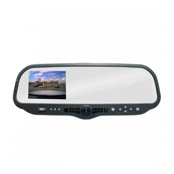
- Page 5 DVM-800 Operation Guide 860-00186-00 Rev L Section 1 Introduction to the DVM-800 System 1.1 Overview of Features • External road facing Camera with 12x variable optical zoom • Two cameras built into the rear view mirror: One forward road facing.
- Page 6 DVM-800 Operation Guide 860-00186-00 Rev L 1.2 DVM Features Diagram 13 14 15 16 LCD Display: Used for viewing video. LCD is behind the mirror and is not visible when off. Internal Microphone: Records audio from the passenger compartment. Manual Record button: This button is used to start/stop a manual event recording.
- Page 7 Section 2 DVM Configuration Overview Many customizable features are available for the DVM-800. The file that is used to update the DVM configuration is named “deviceconfig”. This file contains all of the necessary wireless settings, operational settings, and user logins. Section 3 will guide...
- Page 8 The DVM-800 is shipped with a default configuration so it can be used immediately after installation. However, many parameters can be configured and saved as an activation file. The activation file is saved to a local hard drive or external SD card. The DVM-800 is activated and configured using Digital Ally’s VuVault back-office software.
- Page 9 For more information consult the “VuVault Administrator Guide” Adding Devices section. Go to the Admin > Devices Tab. A separate configuration field for DVM-800 Settings will be available once a valid serial number for the device has been added into the system.
- Page 10 Saving for the configured Local Time Zone. If this is disabled, time will not be adjusted for Daylight Saving. Settings: No, Yes [default] Time Format This time format allows the DVM-800 to be configured in a 12-hour format or a 24-hour format. Settings: 24 Hour, 12 Hour [default] Table of Contents Go Back To Digital Ally, Inc.
- Page 11 DVM-800 Operation Guide 860-00186-00 Rev L Display LCD Brightness The LCD brightness is separately adjustable for day and night modes. To use this setting, choose the desired brightness setting for day and night modes. A light sensor located on the front of the DVM automatically places the system in the correct mode (day or night).
- Page 12 DVM-800 Operation Guide 860-00186-00 Rev L Power The Power operation is configurable and specifies how the DVM will operate when the vehicle ignition is turned to the ON or OFF positions. Two parameters control the power operation in order as follows:...
- Page 13 DVM-800 Operation Guide 860-00186-00 Rev L The following table can be used as a general guideline for determining the Days in LPS setting; actual results may vary: Table 3-6: Number of days a vehicle can remain in Low Power Standby before draining the vehicle battery...
- Page 14 Figure 3-7: DVM Device User prompts if Profile setting is “Enable” 3.5 Record Recording Details Your DVM-800 includes an external 32GB SD card which is used as the primary memory storage. Use the following options in this section to configure your record settings. Record Quality The Record Quality parameter allows the video compression bit rate to be adjusted.
- Page 15 DVM-800 Operation Guide 860-00186-00 Rev L The higher the record quality, the higher the bit rate and the size of the event files. The default setting is Very High for maximum video quality, but can be lowered to Standard or High to increase the compression rate and reduce the required storage space (see Figure 3-8).
- Page 16 860-00186-00 Rev L Record Mode In addition to the external SD Card, the DVM-800 has 32GB of internal memory which is permanently installed in the unit. Select one of the following three modes to determine how the storage memory is utilized.
- Page 17 Cameras The DVM-800 contains two internal cameras, and also supports two external cameras. The DVM can record two video sources simultaneously. You may assign one camera input to each source. The selection you make here will become the default camera selections for all recorded events.
- Page 18 DVM-800 Operation Guide 860-00186-00 Rev L 3.6 Radar The DVM-800 has the ability to display and record radar information in a video recording. Use the Radar section to configure the settings for the specific type of radar that is used.
- Page 19 3.7 Motion Accelerometer The DVM-800 has a built-in accelerometer which can be used to trigger an Event Record when the set G-Force levels are exceeded. The accelerometer can be used to activate an event recording based on the independent G-force levels for acceleration, braking, cornering, collision, and vertical movements.
- Page 20 DVM-800 Operation Guide 860-00186-00 Rev L Vehicle Speed Speed Source The vehicle speed can be used to trigger an event record. Vehicle speed can be calculated through the use of the supplied GPS antenna, or by utilizing the Vehicle Speed Sensor (VSS) signal. The Vehicle Speed Limit can then be adjusted to the speed at which an event record should occur.
- Page 21 DVM-800 Operation Guide 860-00186-00 Rev L 3.8 Sensor The Interface Box (IF Box) is an external module that allows connection to vehicle sensors and triggers. The IF Box provides the DVM system with the capability to add common event record triggers such as emergency lights, reverse, vehicle speed sensor (VSS), brakes, or other sensors.
- Page 22 DVM-800 Operation Guide 860-00186-00 Rev L Name Each input sensor may be given a unique name that will be used to identify the sensor for event recording, playback and metadata reporting. By default, Sensors 1, 2, 3, and 6 are initially reserved for the Reverse Gear, Lights, Brakes, and Wireless Microphone respectively.
- Page 23 DVM-800 Operation Guide 860-00186-00 Rev L Select how the LCD display will operate when a connected IF Box sensor (such as emergency lights, siren, wireless microphone) becomes active. If “No Action” is chosen, the LCD will follow the LCD Mode...
- Page 24 DVM-800 Operation Guide 860-00186-00 Rev L Input Sensor Device Detection, Threshold, and Wiring Guide To configure an input sensor, the signaling of the device must be known. To determine the signaling, measure the voltage for the normal or inactive state of the device and the voltage for the triggered or active state.
- Page 25 860-00186-00 Rev L How to Configure a Backup Camera The DVM-800 can provide a backup camera image on the LCD when the vehicle is shifted into reverse gear. In addition, the DVM-800 can be configured to record the backup event. An optional backup camera or license plate camera kit is required.
- Page 26 DVM-800 Operation Guide 860-00186-00 Rev L The Internal Events box consists of all the configured internal • DVM sensors. These consist of the manual record button, GPS, and accelerometer sensors. These events must be higher in priority than Pre-Event. •...
- Page 27 DVM-800 Operation Guide 860-00186-00 Rev L 3.9 Data Transfer Network The DVM is capable of automatically uploading event files via Wi-Fi to the VuVault ® back office. The DVM must have the Wi-Fi adapter connected and configured for Wi- Fi uploading. The back office network must have at minimum a wireless access point (WAP), and a computer running FTP server software and VuVault software.
- Page 28 > VuVault Settings > WtmLite tab (see the “VuVault Wireless Server Setup Guide”), the Wtm Settings field is used to associate your DVM-800 to the WtmLite server. To begin, click the Add/Remove button to add your DVM to the wireless server. The SSID associated with your configured WtmLite server will then appear in the Wtm Settings box when finished.
- Page 29 Enter the radius of the unauthorized location in miles. To disable an unauthorized location, the latitude, longitude, and radius parameters must all be zero (0). ONCE THE DESIRED SETTINGS HAVE BEEN ENTERED, CLICK SAVE AND PROCEED TO THE NEXT PAGE TO ACTIVATE YOUR DVM-800 MEMORY CARD. Table of Contents 3-22 Go Back To Digital Ally, Inc.
- Page 30 The Status pane will indicate when the process has completed. The SD card can then be placed inside the DVM-800. The DVM will load the configuration files automatically into internal memory (process may take a few minutes). During this process the red, blue, and green LED’s will flash sequentially and the system may reboot.
- Page 31 DVM-800 Operation Guide 860-00186-00 Rev L Section 4 DVM Operation 4.1 Buttons for Operation Function Keys Record Start/Stop Mark Navigation Buttons Play/Pause/REC Ch. 2/ Toggle Display Cursor Up/Down Rewind/Fast Forward Menu/Select/ Audio Mute 4.2 Display and On Screen Information Example...
- Page 32 (Off, On, or Auto) when the DVM is powered on or reset. 4.3 Charging Information The DVM-800 internal battery is charging when ignition power is supplied to the system. 4.4 SD Card Installation & Removal To insert the SD card, position as pictured to the right.
- Page 33 DVM-800 Operation Guide 860-00186-00 Rev L 4.6 DVM Menu Functions The Setup Main menu screen provides access to DVM-800 user configurable settings. Press the Menu/Select button to bring up the menu screen. If a button is not pressed before the configured Entry Timeout expires, the unit will return to Standby mode and the display will turn off.
- Page 34 Adjusting LCD Brightness The global default LCD brightness settings are configured using the VuVault > Devices > DVM-800 Settings > Display menu. These settings can also be configured for each user individually by the Administrator using the VuVault software. To temporarily override the day/night brightness values configured in VuVault, select icon from the Setup Main menu screen.
- Page 35 DVM-800 Operation Guide 860-00186-00 Rev L 4.7 External 12XC Camera Control Buttons The external front facing 12XC Camera is enabled when External 1 is selected as a camera source in the Camera Configuration Menu within VuVault. Focus The NEAR Focus button is used to move the focal point closer to the camera.
- Page 36 Audio The DVM-800 contains a microphone built into the front panel, and an external audio input which is reserved for the DWM Wireless Microphone System. When audio recording is enabled, the DVM-800 will record two stereo audio channels.
- Page 37 Return to the playback list during playback by pressing the button. • Playback list information: The DVM-800 can record two channels simultaneously. In the CH ◦ column, “1” is the front channel and “2” is the rear channel. ◦ DATE = 8-characters in length, representing the date of the event (yyyymmdd).
- Page 38 4.12 Event Id Information Entry The default setting on your new DVM-800 is not to prompt the user to input any event ID information screens after a recorded event. You may choose to enable profiling input data using the VuVault back-office software device configuration.
- Page 39 Beep or Vibration (unless in Covert mode). 3. To end a recording, press the REC button on the DVM-800. The Transmitter cannot be used to stop a recording. 4. At the end of your shift, turn the Transmitter off and place it in the charging Cradle.
- Page 40 DVM-800 Operation Guide 860-00186-00 Rev L 5.4 Notification Alert Switch The switch position determines the notification method provided to the user: • Visible Indicators with audible beep notifications BEEP. • Visible Indicators with vibratory notifications VIB. • Covert operation is achieved by putting the switch in the OFF position.
- Page 41 Transmitter. The entire system must be powered on and in Standby mode to use this feature. 5.10 Remote Accessory Control (Optional wiring is required. Consult the “DVM-800 Installation Guide” for more information) • The Remote Accessory can be used to toggle the Remote Accessory Output on and off.
- Page 42 VuVault back office software is a user friendly software package which ® allows the organization and playback of DVM-800 video, audio and metadata files. It also offers many advanced features such as GPS mapping, security groups, generating reports, printing or saving snapshots, editing, archiving to local storage or DVD’s, and much more.
- Page 43 & configuration file updates. Any authorized user may then playback and analyze video using the VuVault client software (consult the “VuVault Administrator Guide” for more information). There are two ways to set up the DVM-800 wireless transfer: Basic mode and Advanced mode. Decide from the description below which mode works best for your application.
- Page 44 DVM-800 Operation Guide 860-00186-00 Rev L Section 8 Status Indicators The LED status indicators are located next to the Record button, with two more on the front road facing side of the DVM to be viewable from outside of the vehicle.
- Page 45 DVM-800 Operation Guide 860-00186-00 Rev L Section 9 Specifications Power Operating Voltage 13.8VDC 360mA @ 13.8VDC 260uA @ 13.8VDC Low Power Standby 170mA @ 13.8VDC Backup Battery 3.7v, 1150mA, Rechargeable Lithium Ion Polymer Battery Environmental/Mechanical Operating Temperature -20° to +70° C Storage Temperature -40°...
- Page 46 DVM-800 Operation Guide 860-00186-00 Rev L Cameras External 12XC • FOV: 76° (V) x 102° (H) Road Facing Camera • Resolution: 768x494, Color 560TVL, B&W 600TVL • 1/4” Ex-HAD CCD imager • Zoom magnification 12X • Focal Length: f=3.6 ~ 44.3mm, f1.6 (Wide)/ f2.0 (Tele),...
- Page 47 DVM-800 Operation Guide 860-00186-00 Rev L DWM Wireless Microphone System Range 3000 feet typical LOS Communication Bidirectional Microphone Sensitivity -30dB, Maximum Input SPL 110dB Power Consumption External 12VDC, 190mA typical DWM Cradle: 2.75in x 2.99in x 3.15in (70mm x 76mm x 80mm) Size DWM Microphone: 2.5in x 1.8in x 0.94in (64 mm x 46 mm x 24...
- Page 48 860-00186-00 Rev L Section 10 Support & Troubleshooting 10.1 Firmware Updates Firmware updates are periodically necessary to keep your DVM-800 operating at peak performance and to take advantage of all the latest feature enhancements. Log on to http://www.digitalallyinc.com/login.cfm and register for an account to be an authorized user.
- Page 49 DVM-800 Operation Guide 860-00186-00 Rev L Wireless Method 1. Unzip the firmware zip file obtained from the Digital Ally website Customer Portal. 2. Your DVM must be configured for wireless file transfer operation and already be successfully uploading videos to VuVault. Consult the “VuVault Wireless Server Setup Guide”...
- Page 50 The DVM-800 supports 8GB, 16GB, 32GB, Minimum Class 10, commercial grade SDHC cards purchased from Digital Ally ® Formatting Requirements SD Cards used in the DVM-800 should be formatted as a FAT32 file system with allocation block size of 64k bytes. 10.4 Troubleshooting Symptom...
- Page 51 DVM-800 Operation Guide 860-00186-00 Rev L Symptom Resolution Backup Camera is displayed The default operation for the IF Box reverse gear signal is when the vehicle is in Park from Low to High (0VDC to +12VDC). Measure the reverse gear signal voltage at the interface box in the active and non-active state.
- Page 52 DVM-800 Operation Guide 860-00186-00 Rev L Symptom Resolution No wireless download Verify Wi-Fi antenna is plugged into DVM USB port Check DVM configuration and manually place a fresh deviceconfig file from VuVault to the SD card Does problem affect more than one vehicle?
- Page 53 Button 10.7 Product Repair The DVM-800 Digital Video Mirror should be returned to Digital Ally for service. The warranty may be voided if the device is opened by any unauthorized individual. Please contact Digital Ally to obtain an authorized Return Materials Authorization (RMA). It is helpful and will expedite the process if you have your unit’s serial number available at...
- Page 54 860-00186-00 Rev L 10.8 Warranty Information We warranty that our In-Car Digital Video System, Model DVM-800, will be free from defects in workmanship and material for a period of 24 months from the date of purchase by the original purchaser. An optional 60 Month Extended Warranty is also available for purchase.
- Page 55 DVM-800 Operation Guide 860-00186-00 Rev L 10.9 FCC Notice This device complies with Part 15 of the FCC rules. Operation is subject to the following two conditions: (1) This device may not cause harmful interference, and (2) This device must accept any interference received, including interference that may cause undesired operation.
- Page 56 DVM-800 Operation Guide 860-00186-00 Rev L Section 11 Contact 9705 Loiret Blvd Lenexa, KS 66219 www.digitalallyinc.com p: 913.814.7774 f: 913.814.7775 Support E-mail: support@digitalallyinc.com Sales E-mail: sales@digitalallyinc.com Sales / Support Toll Free: 1.800.440.4947 (8am - 5pm CST) Table of Contents 11-1 Go Back To Digital Ally, Inc.
Need help?
Do you have a question about the DVM-800 and is the answer not in the manual?
Questions and answers