Digital-Ally DVM-800 Installation Manual
Hide thumbs
Also See for DVM-800:
- Operation manual (55 pages) ,
- Operation and installation manual (27 pages) ,
- Operation manual (56 pages)
Table of Contents
Advertisement
860-00185-00 Rev L
Installation Guide
DVM-800
Copyright © 2017, Digital Ally, Inc. All Rights Reserved. This publication may not be repro-
duced, stored in a retrieval system, or transmitted in whole or part in any form or by any
means electronic, mechanical, recording, photocopying, or in any other manner without
the prior written approval of Digital Ally, Inc.
Advertisement
Chapters
Table of Contents

Subscribe to Our Youtube Channel
Related Manuals for Digital-Ally DVM-800


Summary of Contents for Digital-Ally DVM-800
-
Page 1: Installation Guide
Installation Guide DVM-800 Copyright © 2017, Digital Ally, Inc. All Rights Reserved. This publication may not be repro- duced, stored in a retrieval system, or transmitted in whole or part in any form or by any means electronic, mechanical, recording, photocopying, or in any other manner without... - Page 2 On behalf of the Digital Ally team, I want to thank you for this order. We appreciate the trust and confidence you have shown us. We will strive to do everything we can to provide you with the best products, support and customer service.
-
Page 3: Table Of Contents
Step 4: Wi-Fi Antenna ....................3-12 Section 4 Testing the Installation ....................4-1 Section 5 Support ........................... 5-1 How to Reset the DVM-800 System ................5-1 Basic Troubleshooting ....................5-1 Interface Box Sensor Worksheet ..................5-3 Section 6 Contact Information ..................... 6-1 Copyright © 2017 Digital Ally, Inc. - Page 4 • Do not connect any Digital Ally wiring in series with a vehicle charge guard or battery saver. All system battery connections must be made to a constant +13.8VDC location within the vehicle.
-
Page 5: Section 2 Parts List And System Diagrams
DVM-800 Installation Guide 860-00185-00 Rev L Section 2 Parts List and System Diagrams DVM-800 Standard Parts Kit 001-00081-00 External Camera Packages are shown on the next page Part # Image and Description 006-08265-31 DVM-800, Main Unit 002-05146-00 DVM Mount Assembly... -
Page 6: External Camera Packages
DVM-800 Installation Guide 860-00185-00 Rev L External Camera Packages Part Number Kit Contents 566-00138-00 Front 12XC Camera • Option 1 566-00134-00 Backseat Camera, • Front 12XC Camera w/Smart IR, Reverse Image Switch, & Backseat Camera Water Resistant (IP69) with 2 Cables •... -
Page 7: Optional Parts
DVM-800 Installation Guide 860-00185-00 Rev L Optional Parts Part Number Image and Description 008-01382-00 Backup Camera 25ft Extension Cable 008-01382-01 Backup Camera 40ft Extension Cable 008-01382-02 Backup Camera 60ft Extension Cable 008-01382-03 Backup Camera 15ft Extension Cable 025-00018-00 DWM-928 External 900MHz Antenna. -
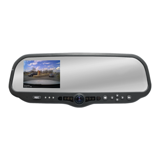
Page 8: Dvm Features Diagram
DVM-800 Installation Guide 860-00185-00 Rev L DVM Features Diagram 13 14 15 16 LCD Display: Used for viewing video. LCD is behind the mirror and is not visible when off. Internal Microphone: Records audio from the passenger compartment. Manual Record button: This button is used to Start/Stop a manual event recording. -
Page 9: System Diagram
DVM-800 Installation Guide 860-00185-00 Rev L System Diagram Table of Contents Go Back To Digital Ally, Inc. Parts List and System Diagrams... -
Page 10: Battery Red
Main Power Cable (page 3-4) +13.8VDC Unswitched Power. Connect directly to the engine compartment battery. DO NOT connect any Battery Digital Ally equipment through a vehicle charge guard or battery saver. +13.8VDC Switched. Powered only when ignition is in Ignition the ACC or On position. -
Page 11: Section 3 Installation Instructions
DVM-800 Installation Guide 860-00185-00 Rev L Section 3 Installation Instructions Step 1: Factory Mirror Removal The current factory rear-view mirror must be removed from the windshield mounting plate. There are several versions of mirror mounting systems. Below are the most common methods of rear-view mirror removal. -
Page 12: Option
DVM-800 Installation Guide 860-00185-00 Rev L Step 2: DVM Installation 1. Install the provided Mirror Mount to the back of the DVM using 3 of the supplied M4 x 6mm black screws. Using the longer 8mm black screw, attach one end the Tether Cable to the Mirror Mount and DVM. -
Page 13: Step 3: Interface Box Installation
DVM-800 Installation Guide 860-00185-00 Rev L Step 3: Interface Box Installation Interface Box The IF Box must be securely mounted on a solid area of the vehicle structure in a moisture free location where it can be easily accessed for reset or replacement. -
Page 14: Ignition
DVM-800 Installation Guide 860-00185-00 Rev L Step 4: Power, Ground, and Input Sensor Power Cable Installation 1. Plug the connector of the Main Power Cable into the IF Box. 2. Route the cable to a suitable location for electrical Main Power Cable connection. -
Page 15: Reverse
DVM-800 Installation Guide 860-00185-00 Rev L IF Input Sensor Cable Installation The IF Box provides multi-purpose sensor inputs that allow external devices to trigger an event record in the mirror. Common external sensors include; emergency lights, siren, brake pedal, vehicle speed sensor, reverse gear, covert foot-switch, or door sensors. -
Page 16: Siren Adapter Interface (Optional)
DVM-800 Installation Guide 860-00185-00 Rev L Siren Adapter Interface (optional) If an acceptable DC output cannot be obtained from the siren controller, the optional Siren Adapter Interface can be used to connect the siren speaker to the interface box. Follow the diagram below to install the siren interface. -
Page 17: Remote Accessory Out
DVM-800 Installation Guide 860-00185-00 Rev L When connecting the 3.5mm Audio Plug to the Ext Mic jack on the back of the DVM, be sure to leave enough slack in the cable to allow for adjustment of the mirror. 3.5mm Audio... -
Page 18: Step 6: External Camera Installation
860-00185-00 Rev L Step 6: External Camera Installation Overview There are 6 External Camera Package options for the DVM-800. Choose the instruction that matches the camera option you have purchased. Option 1: 12XC Camera & Backseat Camera - with 2 Cables 1. -
Page 19: Option 2A And 2B: 12Xc Camera & License Plate Camera
2. Determine a mounting location for the backup camera. Secure the camera using the supplied hardware. 3. Attach the backup camera cable (008-01390-00) to the DVM-800 CAM 2 input. Leave slack in the cable as a service loop and for DVM adjustment;... -
Page 20: Option 3A And 3B: 12Xc Camera, Backseat Camera & License Plate Camera
Y-Cable (008-01443-00) on the CAM 1 port. The License Plate camera uses the CAM 2 port. You must also connect to the vehicle’s reverse gear signal. Please consult the “DVM-800 Operation Guide” for assistance with creating a device configuration file. -
Page 21: Option 4: 12Xc Camera & Backseat Camera - With Y-Cable
1. Attach the visor mount through the visor clip and attach front camera to the mounting plate as shown below. Attach the camera Y-Cable (008-01443-00) to the DVM-800 CAM 1 input. Determine a mounting location for the back seat camera. The example on page 3-8 has the camera mounted in the center of the cage. -
Page 22: Step 3: Gps Module
DVM-800 Installation Guide 860-00185-00 Rev L Step 3: GPS Module Clean the windshield glass with isopropyl alcohol. Plug the GPS Module connector into the port on the back of the DVM and screw the locking ring down. Use full length of cable to locate the GPS module away from the DVM in the upper right or left corner of windshield, outside of the black shaded area. -
Page 23: Section 4 Testing The Installation
DVM-800 Installation Guide 860-00185-00 Rev L Section 4 Testing the Installation Initial Power Up 1. Insert the SD card into the DVM. 2. Turn the vehicle ignition switch to the ON position. The vehicle does not have to be running. -
Page 24: Section 5 Support
Section 5 Support How to Reset the DVM-800 System Using a small blunt object such as a small eye-glass screwdriver or a paper clip, press the reset button on the DVM. The reset button is recessed and on the road facing, driver’s side of the housing as shown here. - Page 25 Backup Camera is visible is connected has 0VDC when in reverse, the DVM will need to when the vehicle is in Park be re-configured. Refer to the “DVM-800 Operation Guide” for additional details for configuring the DVM. • Verify backup camera, cabling, and connectors.
-
Page 26: Interface Box Sensor Worksheet
DVM-800 Installation Guide 860-00185-00 Rev L Interface Box Sensor Worksheet Date: Installer: Vehicle #: Make, Model, Year: License Plate: Vehicle Color: DVM Serial #: VIN Number: To configure an input sensor, the Administrator must know the signaling of the device. -
Page 27: Section 6 Contact Information
DVM-800 Installation Guide 860-00185-00 Rev L Section 6 Contact Information 9705 Loiret Blvd Lenexa, KS 66219 www.digitalallyinc.com info@digitalallyinc.com p: 913.814.7774 f: 913.814.7775 Support E-mail: support@digitalallyinc.com Sales E-mail: sales@digitalallyinc.com Sales / Support Toll Free: 1.800.440.4947 (8am - 5pm CST) Table of Contents Go Back To Digital Ally, Inc.
Need help?
Do you have a question about the DVM-800 and is the answer not in the manual?
Questions and answers