Table of Contents
Advertisement
Quick Links
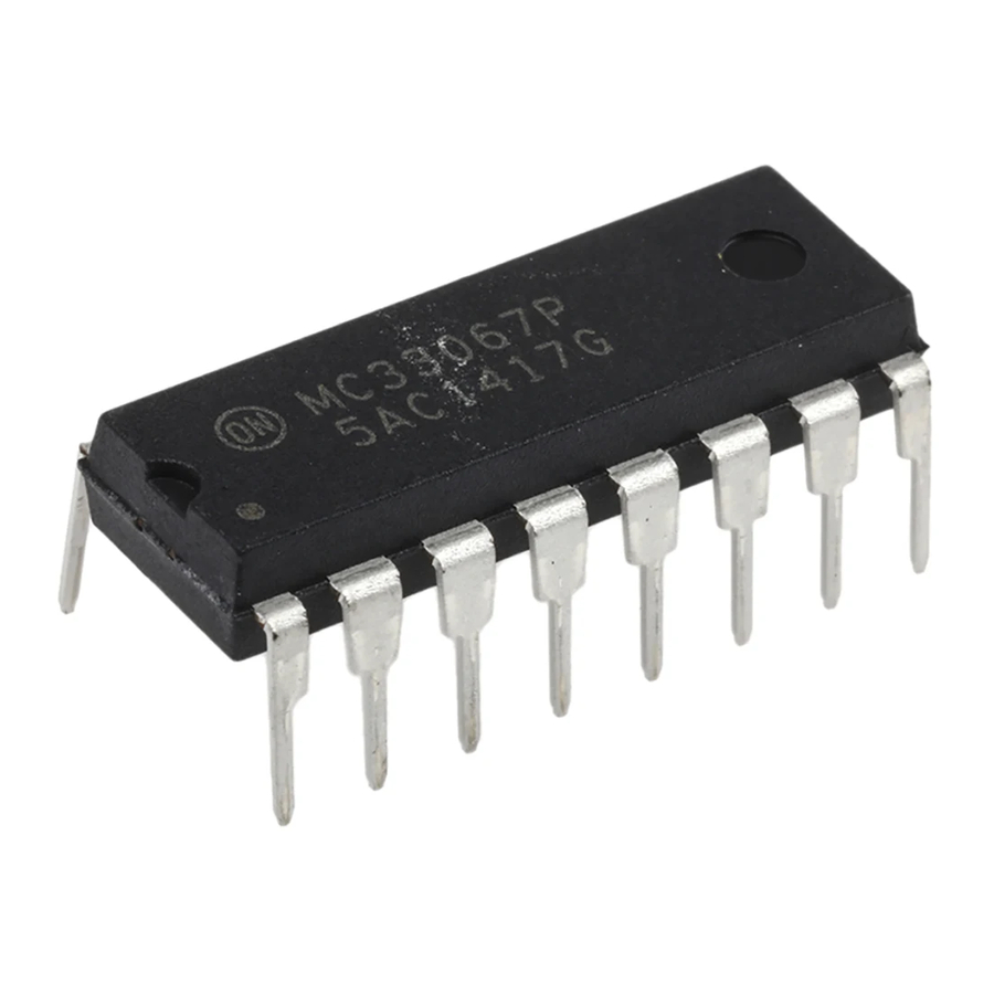
MC34067, MC33067
High Performance
Resonant Mode Controllers
The MC34067/MC33067 are high performance zero voltage switch
resonant mode controllers designed for off−line and dc−to−dc
converter applications that utilize frequency modulated constant
off−time or constant deadtime control. These integrated circuits
feature a variable frequency oscillator, a precise retriggerable
one−shot timer, temperature compensated reference, high gain wide
bandwidth error amplifier, steering flip−flop, and dual high current
totem pole outputs ideally suited for driving power MOSFETs.
Also included are protective features consisting of a high speed fault
comparator and latch, programmable soft−start circuitry, input
undervoltage lockout with selectable thresholds, and reference
undervoltage lockout. These devices are available in dual−in−line and
surface mount packages.
Features
•
Zero Voltage Switch Resonant Mode Operation
•
Variable Frequency Oscillator with a Control Range
Exceeding 1000:1
•
Precision One−Shot Timer for Controlled Off−Time
•
Internally Trimmed Bandgap Reference
•
4.0 MHz Error Amplifier
•
Dual High Current Totem Pole Outputs
•
Selectable Undervoltage Lockout Thresholds with Hysteresis
•
Enable Input
•
Programmable Soft−Start Circuitry
•
Low Startup Current for Off−Line Operation
•
These Devices are Pb−Free, Halogen Free/BFR Free and are RoHS
Compliant
15
V
CC
9
Enable /
UVLO Adjust
1
OSC Charge
2
OSC RC
3
Oscillator
Control Current
16
One-Shot
Error Amp
6
Output
8
Noninverting
Input
Inverting Input
7
11
Soft-Start
*For additional information on our Pb−Free strategy and soldering details, please
download the ON Semiconductor Soldering and Mounting Techniques
Reference Manual, SOLDERRM/D.
© Semiconductor Components Industries, LLC, 2009
December, 2009 − Rev. 13
Downloaded from
Elcodis.com
electronic components distributor
V
UVLO /
5.0 V
CC
Enable
Reference
Variable
Frequency
Oscillator
One-Shot
2.5 V
Clamp
Error
Amp
Soft-Start
4
Ground
Figure 1. Simplified Block Diagram
5
V
ref
V
UVLO
ref
14
Output A
Steering
Flip-Flop
12
Output B
13
Pwr GND
10
Fault Detector/
Fault Input
Latch
1
http://onsemi.com
DIAGRAMS
16
16
AWLYYWWG
1
1
PDIP−16
P SUFFIX
CASE 648
16
16
MC3x067DW
AWLYYWWG
1
SOIC−16W
DW SUFFIX
1
CASE 751G
x
= 3 or 4
A
= Assembly Location
WL = Wafer Lot
YY = Year
WW = Work Week
G
= Pb−Free Package
PIN CONNECTIONS
OSC Charge
1
16
OSC RC
15
2
14
3
OSC Control Current
GND
13
4
V
5
12
ref
Error Amp Out
6
11
Inverting Input
7
10
Noninverting Input
8
(Top View)
ORDERING INFORMATION
See detailed ordering and shipping information in the package
dimensions section on page 2 of this data sheet.
Publication Order Number:
MARKING
MC3x067P
One-Shot RC
V
CC
Drive Output A
Power GND
Drive Output B
C
Soft-Start
Fault Input
Enable/UVLO
9
Adjust
MC34067/D
Advertisement
Table of Contents

Subscribe to Our Youtube Channel
Related Manuals for ON Semiconductor MC33067

Summary of Contents for ON Semiconductor MC33067
- Page 1 MC34067, MC33067 High Performance Resonant Mode Controllers The MC34067/MC33067 are high performance zero voltage switch resonant mode controllers designed for off−line and dc−to−dc converter applications that utilize frequency modulated constant off−time or constant deadtime control. These integrated circuits http://onsemi.com feature a variable frequency oscillator, a precise retriggerable one−shot timer, temperature compensated reference, high gain wide...
-
Page 2: Maximum Ratings
MC34067, MC33067 MAXIMUM RATINGS Rating Symbol Value Unit Power Supply Voltage Drive Output Current, Source or Sink (Note 1) − Continuous − Pulsed (0.5 ms), 25% Duty Cycle Error Amplifier, Fault, One−Shot, Oscillator and Soft−Start Inputs − 1.0 to + 6.0 UVLO Adjust Input −... -
Page 3: Electrical Characteristics
3. Low duty cycle pulse techniques are used during test to maintain junction temperature as close to ambient as possible. 4. T = 0°C for MC34067 = − 40°C for MC33067 = + 70°C for MC34067 high = + 85°C for MC33067 http://onsemi.com... -
Page 4: Soft Start
7. Low duty cycle pulse techniques are used during test to maintain junction temperature as close to ambient as possible. 8. T = 0°C for MC34067 = − 40°C for MC33067 = + 70°C for MC34067 high = + 85°C for MC33067 http://onsemi.com... - Page 5 MC34067, MC33067 3500 = 300 pF = 12 V = 25°C = 200 pF 3000 = 18.2 k 2500 = 500 pF 2000 = 300 pF = 12 V 1500 = ∞ = ∞ 1000 = 500 pF = 25°C Oscillator Discharge Time is Measured at the Drive Outputs.
- Page 6 MC34067, MC33067 Source Saturation = 12 V = - 40°C 80 ms Pulsed Load -1.0 (Load to Ground) 120 Hz Rate = 25°C = - 20°C - 2.0 - 20 = - 40°C - 3.0 = -125°C - 30 = - 40°C = 25°C...
- Page 7 MC34067, MC33067 7.0k 7.0k Enable / 5.1 V UVLO Adjust Reference UVLO 8.0 V UVLO 4.2/4.0 V OSC Charge Output A Steering Oscillator OSC RC Flip-Flop Power Ground 4.9V/3.6 V One-Shot RC One-Shot Oscillator Output B Control Current 4.9 V/3.6 V 3.1V...
-
Page 8: Operating Description
MC34067, MC33067 OPERATING DESCRIPTION Introduction frequencies exceeding 1.0 MHz. The Error Amplifier can As power supply designers have strived to increase power control the oscillator frequency over a 1000:1 frequency conversion efficiency and reduce passive component size, range, and both the minimum and maximum frequencies are... - Page 9 MC34067, MC33067 The minimum frequency is programmed by R using Error Amplifier A fully accessible high performance Error Amplifier is Equation 1: provided for feedback control of the power supply system. − The Error Amplifier is internally compensated and features −...
- Page 10 MC34067, MC33067 The totem−pole output drivers are ideally suited for driving The MC34067 utilizes a unique design that virtually power MOSFETs and are capable of sourcing and sinking eliminates cross conduction, thus controlling the chip power 1.5 A. Rise and fall times are typically 20 ns and 15 ns dissipation at high frequencies.
-
Page 11: Applications Information
MC34067, MC33067 Soft−Start Circuit UVLO Fault The Soft−Start circuit shown in Figure 20 forces the UVLO + Fault variable frequency Oscillator to start at the maximum Fault Fault frequency and ramp downward until regulated by the Comparator Input feedback control loop. The external capacitor at the 9.0 mA... - Page 12 MC34067, MC33067 The maximum duty cycle is controlled by the leakage so that the output switch is activated while the primary inductance, not by the MC34067. The One−Shot in the current is slewing but before the current changes polarity. MC34067 only assures that the power switch is turned on The resonant stage should then be designed to be as long as under a zero voltage condition.
- Page 13 MC34067, MC33067 http://onsemi.com Downloaded from Elcodis.com electronic components distributor...
- Page 14 MC34067, MC33067 (Top View) (Bottom View) 5.0″ 3.875″ Figure 23. Printed Circuit Board and Component Layout http://onsemi.com Downloaded from Elcodis.com electronic components distributor...
-
Page 15: Package Dimensions
MC34067, MC33067 PACKAGE DIMENSIONS PDIP−16 P SUFFIX CASE 648−08 ISSUE T NOTES: −A− 1. DIMENSIONING AND TOLERANCING PER ANSI Y14.5M, 1982. 2. CONTROLLING DIMENSION: INCH. 3. DIMENSION L TO CENTER OF LEADS WHEN FORMED PARALLEL. 4. DIMENSION B DOES NOT INCLUDE MOLD FLASH. - Page 16 PUBLICATION ORDERING INFORMATION LITERATURE FULFILLMENT: N. American Technical Support: 800−282−9855 Toll Free ON Semiconductor Website: www.onsemi.com Literature Distribution Center for ON Semiconductor USA/Canada Order Literature: http://www.onsemi.com/orderlit P.O. Box 5163, Denver, Colorado 80217 USA Europe, Middle East and Africa Technical Support: Phone: 303−675−2175 or 800−344−3860 Toll Free USA/Canada...
Need help?
Do you have a question about the MC33067 and is the answer not in the manual?
Questions and answers