Advertisement
Quick Links
Advertisement

Summary of Contents for Akai 21CTS92FS
-
Page 1: Service Manual
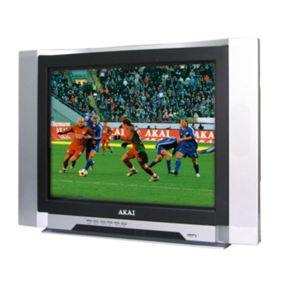
COLOUR TV SET Model: 21CTS92FS SERVICE MANUAL www.akai.ru... -
Page 2: Table Of Contents
21” Colour TV Service Manual Catalogue 1. Technology Specification and Feature…..……………………… Page 1 2. The survey…………………………………………………………… Page 2 3. The main chips instruction…………………………………………. Page 2-4 4. Signal process……………………………………………………… Page 5-6 ……………………………………………………….. Page 6-12 IC illustration ……………………………………………………….Page 13 adjustment method I 2 C bus adjust ...………………………………………………………. -
Page 3: The Survey
2. The survey Table 1, the main IC and functions Number Function Remark Power supply KA5Q0765RT N501 CPU + SIGNAL PROCESSER TDA93x1 N301 Field driver LA78040/STV9302A N401 Sound processor TDA9859 N122 Sound driver AN17821A N161 AV SWITCH TC4052BP N801 (Video) Memory AT24C08 N702... - Page 4 Pin14: +8V power source supply. Pin15: Using a capacitor of 220n in series to GND, This pin decouples the internal digital supply oltage of the video processor and minimizes the disturbance to the sensitive analogue parts. Pin16: PHI-2 control loop, this pin requires a capacitor at 2.2nF (C) in series to GND. Pin17: PHI-1 control loop, the loop filter connected to pin 17 is suitable for various signal conditions ke strong/weak and VCR signal.
- Page 5 Pin39: +8V supply source. Pin40: CVBS input Pin42: Y signal input. Pin43: C signal input. Pin44: Main audio output Pin45: RGB signal input blanking. Pin46, Pin47, Pin48: RGB signal input. Pin49: ABL. It means been current limiter input. The R464 is the control resister. Pin50: Black current input from the CRT board.
-
Page 6: Signal Process
4. Signal process he main chip is N301 TDA93X1 AV control switch HEF4052, sound driver is N101 N17821A。 he TV signal inputs into the tuner (A101) from CABLE or antenna. The pin 10 and pin 11 of the N301 are combined to select the band. The pin 4 of the N301 outputs the PWM tuning signal. The IF video signal comes from the IF pin of the tuner. -
Page 7: Ic Illustration
The outputs (pins 4 and 7) are connected to the series connection of the vertical deflection coil and feedback resistor R404 and R406. The voltage across R404 and R406. is fed via pin 1 to obtain a deflection current which is proportional to the drive voltage. The supply voltage for the TDA8177 is 17V at pin 3. - Page 9 Fig.2 HEF4052BP illustration Fig. 3 TDA8177 illustration Thermal Protection Pump up INVERTING INPUT 5 VER OUTPUT 6 OUTPUT STAGE VCC PUMP UP OUT NON INV.PUT...
- Page 10 Fig. 4 AN17821A illustration...
- Page 11 Fig. 5 KA5Q0765RT illustration...
- Page 12 Fig. 6 TDA9859 illustration...
-
Page 14: Adjustment Method
6 . adjustment method Main power +B setting Receive standard color pattern RF signal,set picture to “ Standard Mode” . Adjust VR501, to get +B (VD631 -) voltage =110 V I 2 C bus control adjustment methed: enter and exit factory mode For remote controller of factory continuous push [test] key on remote controller, the TV mode will change as follow: Normal... - Page 15 1. select RD/BD menu. 2. adjustment RD/BD to get color temperature as x=281, y=311. c) sub-brightness adjustment (use stair case signal) select SB MENU. adjust SB to get the darkest step being on or off. 7.5 MENU6 Set SHIP MODE Select “SHIPMODE”,push [V+][V-]key may be shipped.
- Page 16 Companion sound DK make type choice. ON/OFF Companion sound BG make type choice. ON/OFF Companion sound I make type choice. ON/OFF Companion sound M make type choice. ON/OFF Companion sound make type prior choice. SIF PREFER The automatic companion sound make type identify AUTO SOUND ON/OFF Switch on the power supply appearance choice, know...
- Page 17 16:9 breadths hold a range regulate. WIDE 0~63 Enlarge a range of appearance regulate. ZOOM 0~63 Hold to show a color of the menu headline to regulate. NENU TITLE Switch on the LOGO size choice switch.. LOGO Greatly switch on constitution switch of LOGO. LOGO SIZE Greatly switch on constitution switch of LOGO.
- Page 18 Green encourage to give or get an electric shock the even adjustment. Blue encourage to give or get an electric shock the even adjustment. The vice- bright degree adjust. Note1: TEXT DEF : TXT_def = 0: Pan_Euro + Cyrillic = 1: Farsi English + French + Turkish = 2: Arabic + English + French + Turkish = 3: UKRAINIAN Attention:...


Need help?
Do you have a question about the 21CTS92FS and is the answer not in the manual?
Questions and answers