Table of Contents
Advertisement
Advertisement
Table of Contents

Subscribe to Our Youtube Channel
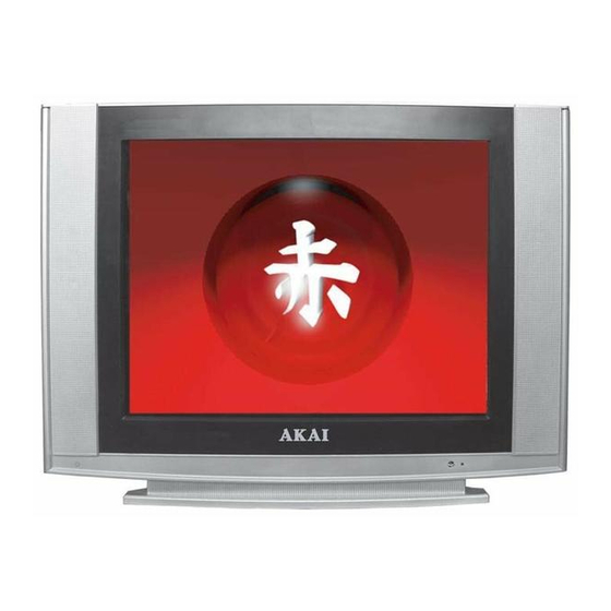
Summary of Contents for Akai 21CTF66BC
- Page 1 Models: 15CTF66BC 21CTF66BC 21CTS65BS...
-
Page 2: Table Of Contents
CONTENTS safety precautions………………………………………………………………………………………2 block diagram…………………………………………………………………………………………….3 3. Replacement of memory IC……………………………………………………………………………4 4. Service adjustment……………………………………………………………………………………...5 5. IC’s functional description………………………………………………………………….…………7 6. Test point waveform…………………………………………………………..…………………….…10 7. IC’s voltages………………………………………………………………………………..….……….11 8. Circuit diagram ……………………………………………………………………………………….. 12... -
Page 3: Safety Precautions
1. SAFETY RECAUTIONS The design of this product contains special hardware, many 10. manufacturer’s replacement components. circuits and components specially for safety purposes. For 11. Isolation Check continued protection, no changes should be made to the (Safety for Electrical Shock Hazard) original design unless authorized in writing by the After re-assembling the product, always perform an isolation manufacturer. -
Page 4: Block Diagram
2 Block Diagram V1 IN V1 IN TUNER IF1 IN TDA111XX IF2 IN V2 IN TDA121XX AL1 IN RF AGC AR1 IN Y IN Y IN U IN U IN V IN V IN V OUT SELECT V OUT AL IN AL OUT AR IN AR OUT... -
Page 5: Replacement Of Memory Ic
3. REPLACEMENT OF MEMORY IC 1. MEMORY IC. This TV uses memory IC. In the memory IC are memorized data for correctly operating the video and deflection circuits. When replacing memory IC, be sure to use IC written with the initial value of data. 2. -
Page 6: Service Adjustment
4. SERVICE ADJUSTMENT 4.1 Enter the factory menu PUSH 【 MENU 】 KEY → DISPLAY PICTURE MANUAL → PUSH DIGITAL KEY “6483” → DISPLAY “B/W BANLANCE” . PUSH 【 STANDBY 】 KEY WILL BE EXIT FACTORY MODE PRESS 【 TEST 】 KEY OR 【 POWER 】 WILL BE EXIT FACTORY MODE IN 【... -
Page 7: Select The Signal In Test.s Menu
Adjust V.size value to get 90% of vertical picture contents would be displayed on CRT Adjust VSC value to vertical S-correction is ok Adjust H.PHASE value to get the picture horizontal center correspond to CRT horizontal center MENU1 PRESET DESCRIPTION TEST.S 0=external signal,1=black... -
Page 8: Ic's Functional Description
WHEN THE WHITE BANLENCE IS OK,AJUST G2 VOLTAGE TO THE SCREEN JUST DISPLAY THE LINE PRESS V+ KEY WILL BE EXIT THE SC LINE MODE MENU2 PRESET DESCRIPTION RF.AGC (VARIABLE 0 63) RF AGC OSD.V.POS 21 16 Vertical position of OSD(0~63) OSD.H.POS 43 18 Horizital position of OSD(0~15)... - Page 9 Vertical sawtooth capacitor IF IN2 Video SAW filter input 2 IF IN1 Video SAW filter input 2 VDRA Vertical drive output A VDRB Vertical drive output B AVL/EW Capacitor for automatic volume leveling or E/W drive output DECBG Bandgap decoupling SECPLL SECAM-PLL oscillator GND1...
- Page 10 BOUT Blue output GOUT green output ROUT Red output BLKIN Feedback input continuous cathode calibration loop and vertical guard input BCLIN Average beamcurrent limiter input Pb input Y3/CVBS3 Y CVBS or Y(C)input PR/C3 Cr input YOUT Y output YSYNC Input sync separator Supply VSP(5V)...
-
Page 11: Test Point Waveform
VCC1 Power VCC2 Output power supply PUMP UP Pump up power NON INV IN Negative feedback Ground 6. Test point Waveforms 2.0Vpp 1.2Vpp 1.2Vpp 1.3Vpp 1.2Vpp TDA111XX PIN1 TDA111XX PIN44 TDA111XX PIN45 TDA111XX PIN46 TDA111XX PIN24 0.9Vpp 5Vpp 95Vpp 95Vpp 95Vpp TDA111XX PIN56 TDA111XX PIN57 CRT KR... -
Page 12: Ic's Voltages
7. IC’s voltages TDA111XX/TDA121XX 0.6 0.35 2.5 STV9302A/LA78040 15.9 -0.07 AN17821/AN17823...


Need help?
Do you have a question about the 21CTF66BC and is the answer not in the manual?
Questions and answers