
Related Manuals for horiba TPNA-500


Summary of Contents for horiba TPNA-500
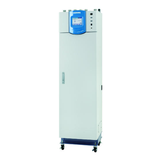
- Page 1 Automatic Total Nitrogen/Phosphorus Monitoring System TPNA-500 Instruction Manual CODE:GZ0000371324D...
- Page 2 HORIBA Advanced Techno, Co., Ltd. warrants that the Product shall be free from defects in material and workmanship and agrees to repair or replace free of charge, at option of HORIBA Advanced Techno, Co., Ltd., any malfunctioned or damaged Product attributable to responsibility of HORIBA Advanced Techno, Co., Ltd.
- Page 3 Regulations Conformable Directive This equipment conforms to the following directives and standards: EMC: EN61326-1 Class A, Industrial electromagnetic environment RoHS: EN50581 9. Industrial monitoring and control instruments Warning: This is a Class A product. In a domestic environment this product may cause radio interference in which case the user may be required to take adequate measures.
- Page 4 FCC rules Any changes or modifications not expressly approved by the party responsible for compliance shall void the user's authority to operate the equipment. Warning This equipment has been tested and found to comply with the limits for a Class A digital device, pursuant to part 15 of the FCC Rules.
- Page 5 China regulation 本标记适用在中华人民共和国销售电器电子产品, 标记中央的数字表示环境保护使用期限的年数。 (不是表 示产品质量保证期间。 ) 只要遵守这个产品有关的安全和使用注意事项, 从制造日开始算起在这个年限内, 不会给环境污染、 人体和财产带来严重的影响。 请不要随意废弃本电器电子产品。 This marking is applied to electric and electronic products sold in the People's Republic of China. The figure at the center of the marking indicates the environmental protection use period in years. (It does not indicate a product guarantee period.) It guarantees that the product will not cause environment pollution nor serious influence on human body and property within the period of the indicated years which is counted from the date of manufacture as far as the safety and usage precautions for the product are...
- Page 6 For Your Safety Hazard classification and warning symbols Warning messages are described in the following manner. Read the messages and follow the instructions carefully. Hazard classification This indicates an imminently hazardous situation which, if not avoided, will result in death or serious injury. This is to be limited to the most extreme situations.
- Page 7 Safety precautions This section provides precautions for using the product safely and correctly and to prevent injury and damage. The terms of DANGER, WARNING, and CAUTION indicate the degree of imminency and hazardous situation. Read the precautions carefully as it contains important safety messages.
- Page 8 Attachment location and type of warning labels Attachment location of warning labels (For automatic hydrochloric acid cleaning specification)
- Page 9 Type (5) 2 type labels (6) For automatic hydrochloric acid cleaning specification...
- Page 10 Product Handling Information Operational precautions Use of the product in a manner not specified by the manufacturer may impair the protection provided by the product. And it may also reduce product performance. Exercise the following precautions: Only use the product including accessories for their intended purpose. ...
- Page 11 Manual Information Description in this manual Note This interprets the necessary points for correct operation and notifies the important points for handling the product. Reference This indicates the part where to refer for information. This indicates reference information.
-
Page 13: Table Of Contents
Contents Before Using the Product ....... . Preface ........... Names of each part . - Page 14 Operation stop ..........When stopping the equipment for over three days .
- Page 15 MEASURE VALUE ..........TREND GRAPH (MEASURE VALUE).
- Page 16 Others (writing of setting) ......... Maintenance .
-
Page 17: Before Using The Product
“Manual of measurement methods for water quality pollutant load using nitrogen/phosphorus automatic measurement instrument (published by Japan's Ministry of the Environment)” can be used. The TPNA-500 uses the ultraviolet oxidative dissolution method. Ultraviolet oxidative dissolution method ... -
Page 18: Names Of Each Part
Before Using the Product Names of each part Analyzer [When open] Refer to page 3. [Models equipped with a pure water tank] Name Description Operation section Refer to “ Operation section” (page 5). Electrical wiring service A service entrance for electrical wiring. entrance Input/output terminal Power supply cable and signal lines are brought into the equipment here. - Page 19 Before Using the Product [Pure water supply from customer] [For the built in pure water cartridge] Name Description3 Measures sample solution and diluted sample solution. Dilution tube The sample solution is diluted with pure water according to the sample concentration. Pure water Measures pure water.
- Page 20 Before Using the Product Name Description3 Solenoid valve(pure It is an solenoid valve for control of pure water supply. water supply) In the case of specifications with built in pure water cartridge, it is attached. Pure water cartridge Pure water necessary for the measurement is purified when you supplies tap water. Can use it between six months from one year.
-
Page 21: Operation Section
Before Using the Product Operation section Name Description The printer and its paper, and an automatic printer-paper spooling unit are housed Printer door behind this door. Displays measurement results, including measurement values, time, and measurement point, condition settings, operating guidance for maintenance/ Touch panel adjustment, alarm description, and function key guidance. -
Page 22: Display
Before Using the Product Display A typical screen example will be used to explain the content displayed on the screen. Note The display is a touch panel device. Do not operate the touch panel using the tip of your finger nail or a tool with a sharp edge, or with wet hands. - Page 23 Before Using the Product Display details of the selected item Screen will show details of each item. Description Details Screen title ALARM HISTORY, etc. Description of Shows the currently displayed item. table contents Details of Shows details of display items. display item Operation Switches displays, etc.
- Page 24 Before Using the Product Description of icons A: Description of the display item icons Item Icon Description Pre-processing Preparation prior to start of measurement. The sample, pure water, and reagents are measured and injected into the Sampling dissolution sections. Solutions are exposed to ultraviolet light and heated to cause dissolution of the Dissolution compounds in the sample.
- Page 25 Before Using the Product B: Description of equipment status icons Item Icon Description Critical (red) Alarm An alarm is activated. For details on how to check past alarm, refer to activated “ [DATA] - [ALARM HISTORY]” (page 147). Minor (yellow) No alarm No display No alarm is activated.
-
Page 26: How To Change Authority
Before Using the Product How to change authority 1. Press the icon. 2. Press the relevant authority button. 3. Enter your password and press [ENTER]. -
Page 27: Connection
Connection Connection Signal wiring External input/output The input/output terminal connection diagram for this equipment is shown below. The screw connection terminals inside the operation panel are used for the input/output terminals. Connect the signal lines according to the signal table. ... - Page 28 Connection Perform terminal processing for the signal lines as illustrated below. For analog input/output and For RS communication contact input/output 0.75 mm to 2.5 mm (AWG18 to 14) 7 mm Signal line terminal processing 0.14 mm to 2.5 mm (AWG26 to 14) 7 mm 5.2 mm (max.) 4 mm (max.)
-
Page 29: Analog Output
Connection Analog output In this equipment, the measurement values are output via the analog current/voltage output terminals. There are four analog output lines as standard. For output, select the desired four components from the following five. The values are output in accordance with the specified full-scale value. Measurement item ... - Page 30 Connection Measurement item and analog output range Example of 4 mA to 20 mA output Measurement Range 4 mA output 20 mA output item TP Conc. L1 10 mg/L 0 mg/L 10 mg/L Example of 0 mA to 16 mA output Measurement Range 0 mA output...
- Page 31 Connection Initial allocation of analog output The allocation of terminals for the measurement value analog output is listed below. Standard specification Terminal No. Output No. Initial allocation AO 00 () TP Conc. L1 AO 00 () AO 01 () TN Conc.
- Page 32 Connection Analog output standard The analog current output standard is shown below. Input/output Signal type Standard circuit Current signal output 0 mA to 16 mA DC/4 mA to 20 mA Analog signal Isolated output (shared common) output Load resistance: 500 ...
-
Page 33: Analog Input
Connection Analog input In this equipment, the measurement values are externally input via the analog current/voltage input terminal. There is one analog input line as standard, and flow meter L1 is selected. Note The analog input selection is configured at the factory according to the customer's specifications. Item ... - Page 34 Connection Initial allocation of analog input The allocation of terminals for the flow rate analog input is listed below. Standard specification Terminal No. Output No. Initial allocation AI00 () Flow Meter L1 AI00 () 3-component specification Terminal No. Output No. Initial allocation AI01 () UV/COD L1...
-
Page 35: Contact Output
Connection Contact output This equipment is equipped with the contact outputs described below. Each output item is enabled when the relevant contact is set, and the following operation also becomes available. Output item Standard specification Item Description SYNCHRONOUS IDLE 1 Specified synchronous signal 1 is output. - Page 36 Connection Item Description TP H.Hi Conc. L1 The TP concentration for the L1 line has exceeded the final upper limit value. The accumulated value of the TP load (TP concentration x flow meter) for the TP Hi Load L1 L1 line has exceeded the specified upper limit value. TN Hi Conc.
- Page 37 Connection Item Description Flow Mainte L2 The flow meter of the L2 is under maintenance. Flow Err. L2 The flow meter of L2 has an error. Flow Power L2 The power for the flow meter of L2 is down. Flow No Drain L2 No drainage through L2 flow meter.
- Page 38 Connection 3-component specification Terminal Output No. Initial allocation PO 16 COD Hi Conc. L1 PO 16 PO 17 COD H.Hi Conc. L1 PO 17 PO 18 COD Hi Load L1 PO 18 PO 19 No allocation PO 19 PO 20 No allocation PO 20 PO 21...
- Page 39 Connection Contact output standard The contact output standard is shown below. Signal type Input/output circuit Standard Contact rating 250 V AC 3 A 30 V DC 3 A Contact (Note: However, only 30 V DC 3 A is available for the “Maintenance” contact.) output signal Contact output ...
-
Page 40: Contact Input
Connection Contact input This equipment has the following built-in contact input items. Each input item is enabled when the relevant contact is set, and the following operation also becomes available. Note The contact input selection is configured at the factory according to the customer's specifications. Input item ... - Page 41 Connection Only available for 2-point meter specification Start signal type Item Description Input condition For pulse For level setting setting The contact is ON (short-circuited) Accepts Samp. Lack Samp. Lack L2 for at least 10 seconds after the OFF Level reading Level reading (release) status.
- Page 42 Connection Initial allocation of contact input The allocation of terminals for the contact input is listed below. Standard specification Terminal Output No. Initial allocation PI 00 Line Select L1 PI 00 (G) PI 01 Flow Mainte L1 PI 01 (G) PI 02 Flow Err.
- Page 43 Connection Terminal Output No. Initial allocation PI 17 No allocation PI 17 (G) 2-point meter specification Terminal Output No. Initial allocation PI 09 Line Select L2 PI 09 (G) PI 10 Flow Mainte L2 PI 10 (G) PI 11 Flow Err. L2 PI 11 (G) PI 12 Flow Power L2...
- Page 44 Connection Contact input standard The contact input standard is shown below. Signal type Input/output circuit Standard Contact rating ON resistance: 100 (max.) +24 V Release voltage: 26 V DC (max.) Contact input Short-circuit current: 13 mA (max.) 2.2 k...
-
Page 45: Serial Input/Output (Rs-485/Rs-232C)
Connection Serial input/output (RS-485/RS-232C) This equipment is provided with RS-485 (standard) or RS-232C (option) input/output terminals. Specifications are as described below. For details on the commands, refer to “ Modbus” (page 161). Configured at the factory Interface RS-485 (standard) RS-232C (option) ... -
Page 46: Preparation For Operation
If the printer runs out of paper, printing cannot be performed. The printer paper for the TPNA-500 is a highly sensitive thermal paper for high-speed printers. For purchase of the printer paper, specify the parts code listed in “ Accessories and consumables”... -
Page 47: Installation Of Reagent Bottle
While the reagent tray is pulled out, do not place anything other than the reagent bottle specified by HORIBA Advanced Techno. When setting or replacing the reagent, match the color of the tube connected to the nozzle unit ... - Page 48 Preparation for Operation 1. Loosen the knurled screw (one location) and remove it. 2. Pull out the reagent tray. Reagent F Reagent A Reagent E Reagent unit Span solution Reagent D Reagent tray Reagent C Reagent B Knurled screw 3. Remove the cap of a new reagent bottle, check that the color of the tube matches that of the label of the reagent bottle, and attach the nozzle unit.
- Page 49 Preparation for Operation 4. Set the reagent bottle in the reagent tray as illustrated below. Reagent F Reagent A Reagent E Span solution Reagent D Reagent tray Reagent C Reagent B Knurled screw 5. Return the reagent tray to its original position and tighten the knurled screw.
-
Page 50: Preparation Of Reagent
Preparation for Operation Preparation of reagent Note For preparation, be sure to use pure water (ion-exchange water) with conductivity of 0.05 mS/m or less. For measurement of a reagent, be sure to use a calibrated balance with reciprocal sensitivity of ... -
Page 51: Preparing Potassium Peroxodisulfate Aqueous Solution [Reagent A]
Preparation for Operation Preparing potassium peroxodisulfate aqueous solution [Reagent A] Note For potassium peroxodisulfate used here, be sure to use one for nitrogen and phosphorous measurement. Use of special grade is not permitted. When dissolving the reagent, do not heat it (or else the reagent will self-decompose). ... -
Page 52: Preparing L-Ascorbic Acid Aqueous Solution [Reagent D]
Preparation for Operation Preparing L-ascorbic acid aqueous solution [Reagent D] 1. Measure 6 g of L()-ascorbic acid (special grade). 2. Pour approximately 200 mL of pure water into a container. 3. Dissolve the above measured reagent completely in this container. 4. -
Page 53: Preparation Procedure Of Span Solution
Preparation for Operation Preparation procedure of span solution Preparation of undiluted solution for nitrogen calibration 1. Dry potassium nitrate (99 GR) at 105C to 110C for three hours. After drying, slowly cool the potassium nitrate to room temperature in a desiccator. 2. - Page 54 Preparation for Operation List of calibration solution measurement values (total nitrogen) Amount of Undiluted Total amount Equipment Preparation Potassium undiluted solution of undiluted Total amount range concentration nitrate solution to be concentration solution collected mg N/L mg N/L mg N/L 1000 7.218 1000...
-
Page 55: Preparation For Pure Water Supply
Preparation for Operation Preparation for pure water supply For models equipped with a pure water tank 1. Disconnect the tube and connector for float sensor from the pure water tank. Connector for float sensor Pure water tank (option) 2. Remove the pure water tank. 3. - Page 56 Preparation for Operation Pure water criterion (JIS K0557: 1998 “Water used for industrial water and wastewater analysis”) Item Electrical conductivity mS/m 0.5 or less 0.1 or less 0.1 or less 0.1 or less (25C) Organic carbon (TOC) mg C/L 1 or less 0.5 or less 0.2 or less 0.05 or less...
- Page 57 Preparation for Operation Attachment of the pure water cartridge (For the built in pure water cartridge) 1. Take out the two caps attached on the in/out ports of the pure water cartridge. The in/out ports of the pure water cartridge Two caps 2.
- Page 58 Preparation for Operation 3. Check that the pipings outside are complete, then close the V-1 valve and open the V-3 valve for leading tap water to purge inside of the pipings. Basic purge time ; about 5 minutes (Depending on the workmanship of the pipe construction) V-3 valve V-1 valve...
- Page 59 Preparation for Operation 6. When the purging for the cartridge is complete, push 【Pure water purge】 to finish purging. Note The hose between the tap water supply and the inlet of the instrument must be low extraction property. Recommended hose; Kakudai 597-515 (ID 15 mm OD 20 mm) The water to the pure water cartridge should be the same level of quality for the tap water.
- Page 60 Preparation for Operation In the case of pure water supply from a customer 1. Confirm that plumbing is carried out definitely.Open V-1 valve and supply pure water to purge the plumbing next. (Basic purge time: about 5 minutes) V-1 valve 2.
-
Page 61: Installation Of Chemical Tank (For Automatic Hydrochloric Acid Cleaning Specification)
Preparation for Operation Installation of chemical tank (for automatic hydrochloric acid cleaning specification) WARNING Chemical hazard Dissolving the reagent generates hydrochloric vapor and heat. When mixing the cleaning solution, be sure to wear protective goggles and gloves. • Dissolve the reagent in a well-ventilated area such as a draft chamber. •... -
Page 62: Line Cleaning Solution
Preparation for Operation Line cleaning solution For the cleaning solution, 5% diluted hydrochloric acid is recommended. When dissolving the reagent, cool the container with water or ice as necessary. How to prepare the cleaning solution 1. Prepare 600 mL of hydrochloric acid (special grade: 35% to 37% hydrochloric acid). 2. -
Page 63: Operation
Operation Operation Operation method There are the following types of operation method. (1) Internal control The operation is controlled according to the internal time settings specified in the meter. (2) Schedule (interval measurement) In this mode, the operation is performed according to the specified schedule. Other than measurement, the stopping and cleaning operations can also interrupt the operation. -
Page 64: For Initial Operation
45 and 46 for JIS K0102 (measurement value obtained by the specified measurement method), and the TPNA-500, the following conversion formula should be used. The conversion formula is expressed as follows:... -
Page 65: Operation Start
Operation Operation start 1. Turn ON the main power switch located behind the operation section door at the front of the equipment, and then turn ON the power switch at the front of the equipment. After Now Loading... is displayed, wait for a while until the main screen is displayed. Note While Now Loading... -
Page 66: Operation Stop
Operation Operation stop When stopping the equipment for over three days 1. Stop the equipment (refer to “ STOP RESERVE” (page 158)). 2. Turn ON the maintenance switch. 3. Perform the following operation. [MENU] [SETTING] MENU Main MAINTENANCE Refer to “ To display the [MENU] item screen” (page 62). 4. - Page 67 Operation 7. Remove the nozzle unit for reagent B, and then replace it with a reagent bottle filled with pure water. Label: Blue Reagent B bottle Bottle filled with pure water 8. After the bottle replacement, perform the following operation. [MENU] [SETTING] Main...
-
Page 68: Operation Restart
Operation Operation restart Note When the power starts up, the latest value before the power was previously turned OFF is displayed. The latest value is taken from the history data read from the CF card. If there are no history data, no data is output on the display. -
Page 69: Calibration
Calibration Calibration Perform calibration in order to pre-determine the zero point and full-scale point for total nitrogen and total phosphorus. Calibration pattern It is necessary to perform calibration periodically. For calibration, always perform zero calibration, and then span calibration, in this order. Description of each calibration Calibration Description... - Page 70 Calibration There are three methods of calibration as follows. (1) When the operation mode is set to local To perform automatic calibration (refer to “ AUTO CAL. SET” (page 70)) Perform settings in the AUTO CAL. SET screen and start the operation. Calibration will interrupt the operation at the specified interval.
-
Page 71: Calibration Procedure
Calibration Calibration procedure Points to check before calibration Check the following. Sufficient reagent and pure water remain The calibration cycle and count are set (refer to “ AUTO CAL. SET” (page 70)) Operation procedure 1. Press [START] in the main screen. [START] [CALIBRATION] 2. -
Page 72: Function
Function Function The TPNA-500 features various functions. In order to use them, it is necessary to set the conditions in advance. This chapter describes the details of each function and its setting procedure. Description The operation procedure is explained in the following manner. -
Page 73: List Of Functions
Function List of functions Fully understand the functions and set them as desired at the customer’s site. Function Details Reference Allows you to specify the settings concerning the receipt and allocation SETTING of external signals, as well as the input/output of those signals during Page 63 operation. -
Page 74: Hierarchy Of Functions
Function Hierarchy of functions MENU (page 62) SETTING (page 63) “ OPERATION SET” (page 63) “ OPERATION MODE SET” (page 64) Control Mode, Start Signal, Measure Mode, Meas. Element “ AUTO MEAS. (SCHE) SET” (page 65) Meas. Start Time, Meas. Schedule, Weekly Pattern “... - Page 75 Function “ MAINTE OUTPUT SET” (page 95) Output Mode, Preset “ WARMUP OUTPUT SET” (page 96) Output Mode, Preset “ DATA DISP. SET” (page 97) Minus Data, Full-scale Over “ PAYLOAD SET” (page 98) Function, Date (Hourly), Date (Daily), Unit, Flow F.S. L1, L2 “...
- Page 76 Function Pre-Wash Preprocess Discharge all Pure water purge Check Press CHECK (page 122) “ MACHINE INFORMATION” (page 122) MAIN BOARD INFO./SUB BOARD INFO. “ EXT. POINT INPUT” (page 123) EXT. POINT INPUT ON/OFF “ EXT. POINT OUTPUT” (page 124) EXT. POINT OUTPUT ON/OFF “...
- Page 77 Function Measure Line, Start Time, Vertical Top, Vertical Under, Meas. Element, Pulse Type “ TREND GRAPH (OPTICAL SIGNAL)” (page 144) Vertical Top, Vertical Under, Meas. Element, Pulse Type, Measure Line CALIBRATION HISTORY (page 146) Measurement element PRINT ALARM HISTORY (page 147) PRINT SAVE TO USB (page 148) DATA CLEAR (page 156)
-
Page 78: To Display The [Menu] Item Screen
Function To display the [MENU] item screen 1. Press [MENU] in the main screen. The MENU screen will be displayed. 2. Select the relevant item using button displayed on the MENU screen. The screen for the selected menu item will be displayed. Reference “... -
Page 79: [Menu] - [Setting]
Function [MENU] - [SETTING] Specifies the following settings. Item Description Reference OPERATION Specifies the operation mode, automatic operation schedule, automatic Page 63 cleaning, and automatic calibration schedule. Specifies whether the line is to be operated/stopped, conversion MEAS. LINE SET Page 75 coefficient of the line, and concentration alarm. - Page 80 Function OPERATION MODE SET Specifies the operation mode. Default Item Setting range Description value Local No external control Control Mode Remote (contact) Local Controls measurement by the contact input. Remote (communication) Controls measurement by the communication commands. Pulse Starts measurement by the pulse input. Start Signal Pulse Performs measurement according to the measurement mode...
- Page 81 Function AUTO MEAS. (SCHE) SET Specifies the automatic measurement (when scheduled measurement is performed). Default Item Setting range Description value Specifies the time (minute) to start the Meas. Start Time 0 to 59 0 min measurement. Measure Allows you to select from Measure L1, Stop, Meas.
- Page 82 Function [AUTO MEAS. (SCHE) SET] AUTO MEAS. (SCHE) SET OPERATION SET 1/2 Meas. Start Time Meas. Start Time Meas. Schedule [ → ] [ ← ] MEAS. SCHEDULE 1/2 MEAS. SCHEDULE 2/2 [Pattern 1] <Specify various Schedule 1 settings> [ →...
- Page 83 Function AUTO MEAS. (REP) SET Specifies the automatic measurement (when repeat measurement is performed). Default Item Setting range Description value 0 hour 1 hour 2 hours 3 hours Operation Cycle 1 hours Performs measurement at the specified interval. 4 hours ...
- Page 84 Function AUTO HCl WASH SET Specifies the automatic hydrochloric acid cleaning. The automatic hydrochloric acid cleaning specification is available as an option. During the automatic hydrochloric acid cleaning process, the sample lines are cleaned. Cleaning is performed within the 1-hour measurement period. If dirt is excessively accumulated in a sample line due to the long-term use, it could affect the reading.
- Page 85 Function [AUTO HCl WASH Function SET] Function L1 AUTO HCl WASH SET 1/3 OPERATION SET 1/2 [ → ] [ ← ] Cycle Cycle [ → ] [ ← ] Start Date OPERATION SET 2/2 Start Date Function Function L2 AUTO HCl WASH SET 2/3 Cycle Cycle...
- Page 86 Function AUTO CAL. SET Specifies the automatic calibration. Item Setting range Default value Description Function Select whether or not to use the setting. Cycle 1 to 31 1 day Determines the automatic calibration cycle. 2009/01/01 00 Start Date 2009/01/01 00 Specify the initial automatic calibration date. to 2099/12/31 23 Determines the number of times to perform calibration per zero calibration.
- Page 87 Function [AUTO CAL. SET] Function Function AUTO CAL. SET 1/3 OPERATION SET 1/2 Cycle Cycle <Input a value> [ → ] [ ← ] Start Date Start Date ZERO Cal. Count SPAN Cal. Count ZERO Cal. Count Pre-Wash Count SPAN Cal. Count AUTO CAL.
- Page 88 Function AUTO WASH SET (Not supported) Specifies the cycle and start time of the automatic reagent line cleaning. For the automatic reagent line cleaning process, the reagent E line is cleaned. Reagent E has a tendency to crystallize. Specifying periodic automatic cleaning will enable stable measurement to be performed continuously.
- Page 89 Function [AUTO Function WASH SET] Function AUTO WASH SET OPERATION SET 1/2 Cycle <Input a value> Cycle Start Date Start Date...
- Page 90 Function OFF-LINE SET Specifies the off-line measurement. Item Setting range Default value Description Specifies whether or not to perform the off-line OFF-LINE MODE measurement. In the off-line measurement mode, a bottled sample is measured. When the off-line mode is set to ON, the sample is not discharged from the sampling tube but discharged from the drain tube of the overflow tank.
-
Page 91: Meas. Line Set
Function MEAS. LINE SET Specifies whether the line is to be operated/stopped, conversion coefficient of the line, and concentration alarm. Item Description Reference LINE CHANGE SET Specifies the allocation of the measurement line. Page 76 CONV. COEF. SET Specifies the conversion coefficient. Page 77 CONC. - Page 92 Function LINE CHANGE SET Specifies the allocation of the measurement line. Default Item Setting range Description value Line No. L1 to L2 1 to 99 Specifies the sample line to be used. Line Select L1 to L2 Stop Working Working Select either “Stop”...
- Page 93 Note: L2 can be selected only for the two-point meter specification. Note Specify the conversion coefficient only in the special case when there is no correlation between the measurement value from manual analysis and that of the TPNA-500. Operation procedure [MENU] [SETTING] [MEAS.
- Page 94 Function 2. Specify the conversion coefficient. [CONV. Revision COEF. a L1 SET] Revision a L1 <Input a value> CONV. COEF. SET (TP) MEAS. LINE SET [Element] Revision b L1 <Input a value> Revision b L1 Revision a L1 Revision a L1 <Input a value>...
- Page 95 Function CONC. ALARM SET Specifies the TP/TN concentration alarm value. Item Setting range Default value Description Specifies the upper limit alarm value for the Hi Limit L1 to L2 0.0000 mg/L to 2000 mg/L 0.0000 mg/L TP/TN concentration. Specifies the final upper limit alarm value for H.Hi Limit L1 to L2 0.0000 mg/L to 2000 mg/L 0.0000 mg/L...
- Page 96 Function 2. Specify the TP/TN concentration alarm value. [CONC. ALARM Hi Limit SET] Hi Limit L1 <Input a value> CONC. ALARM SET (TP) MEAS. LINE SET [Element] H.Hi Limit H.Hi Limit L1 <Input a value> Hi Limit L1 Hi Limit L1 <Input a value>...
- Page 97 Function LOAD ALARM SET Specifies the TP/TN load alarm value. Item Setting range Default value Description 0.00 kg/d to Specify the load (= each element concentration x flow Hi Limit L1 to L2 0.00 kg/d 9999999 kg/d rate) alarm value. Note 1: L2 can be selected only for the two-point meter specification.
- Page 98 Function FLOW ALARM SET Specifies the flow rate alarm value. Item Setting range Default value Description Hi Limit L1 to L2 Specify the flow rate alarm value. 0.00 m /d to 9999999 m 0.00 m Note 1: L2 can be selected only for the two-point meter specification. Note 2: When these parameters are set to 0.0000, no alarm will be activated.
-
Page 99: Output Set
Function OUTPUT SET Specifies the following settings. Item Description Reference EXT. POINT OUTPUT SET Specifies the external contact output. Page 83 EXT. ANALOG OUTPUT SET Specifies the analog output. Page 90 DATA OUTPUT SET Specifies the data output. Page 92 DATA DISP. - Page 100 Function [EXT. PO ASSIGN] [EXT. POINT OUTPUT SET] EXT. PO SET OUTPUT SET [ → ] [ → ] [ → ] [ ← ] [ ← ] [ ← ] EXT. PO ASSIGN 2/4 EXT. PO ASSIGN 4/4 EXT. PO ASSIGN 1/4 EXT.
- Page 101 Function SYNCHRONOUS IDLE Specifies the synchronous signal. Setting Default Operation mode Description range value The time period for which the signal is turned ON in 0 sec synchronization with the measurement sequence. SYNCHRONOUS -3,600 sec IDLE 1 to 3600 sec The time period for which the signal is turned OFF in 3600 sec synchronization with the measurement sequence.
- Page 102 Function TOTAL ALARM ASSIGNMENT Specifies the allocation of total alarm. Setting item No allocation Maintenance Maintenance UV WarmUp WarmUp-UV Int.memory Err. Clock Err. Int. Power Int.comm. Err. CAN Comm. UV Heat High Temp Lamp Err. Lamp UV Cell Motor Temp. Sensor Err. Lack Blank Full Drain Tank Lo Temp Machine...
- Page 103 Function <Select> <Select> TOTAL ALARM 1/2 to 2/2 TOTAL ALARM 1/10 to 10/10 Default settings Default value TOTAL ALARM 1 TOTAL ALARM 2 TOTAL ALARM3 TOTAL ALARM 4 TOTAL ALARM 5 TOTAL ALARM 6 01 Int.memory Err. 02 Clock Err. 03 Int.
- Page 104 Function Default value TOTAL ALARM 1 TOTAL ALARM 2 TOTAL ALARM3 TOTAL ALARM 4 TOTAL ALARM 5 TOTAL ALARM 6 No allocation...
- Page 105 Function MAINTE OUTPUT SET Specifies the maintenance output. Item Setting range Default value Description Specifies ON/OFF of the contact output when Point Output the maintenance switch is turned ON. Reference For details on the default settings, refer to page 87. Operation procedure [MENU] [SETTING]...
- Page 106 Function EXT. ANALOG OUTPUT SET Specifies the analog output. Item Setting range Default value Description Outputs a signal within the range from 0 0 mA to 16 mA mA to 16 mA for the full scale of the measurement range. Output Level 4 mA to 20 mA Outputs a signal within the range from 4...
- Page 107 Function [EXT. ANALOG OUTPUT SET] <Select various settings> EXT. ANALOG OUTPUT OUTPUT SET Output Level Output Level Output Limit Output Limit Output <Select> Assign EXT. DA ASSIGN <Select> Output F.S. <Input a value> EXT. DA F.S.
- Page 108 Function DATA OUTPUT SET Specifies the data output. Item Description Reference CAL. OUTPUT SET Specifies the TP/TN concentration analog output during calibration. Page 92 Specifies the TP/TN concentration analog output during alarm ALARM OUTPUT SET Page 94 activation. Specifies the TP/TN concentration analog output during MAINTE OUTPUT SET Page 95 maintenance.
- Page 109 Function [DATA [CAL. OUTPUT OUTPUT SET] SET] DATA OUTPUT OUTPUT SET Output Mode CAL. OUTPUT Output Mode Preset Preset <Input a value>...
- Page 110 Function ALARM OUTPUT SET Specifies the alarm output. Item Setting range Default value Description Locks TP/TN concentration analog output during alarm Hold activation to the previous value. Locks TP/TN concentration analog output during alarm Output Mode Preset Hold activation to a preset value. Outputs the measurement value to the TP/TN Direct concentration analog output during alarm activation.
- Page 111 Function MAINTE OUTPUT SET Specifies the maintenance output. Item Setting range Default value Description Locks the TP/TN concentration analog output during Hold maintenance to the previous value. Locks the TP/TN concentration analog output during Output Mode Preset Hold maintenance to the preset value. Outputs the measurement value to the TP/TN Direct concentration analog output during maintenance.
- Page 112 Function WARMUP OUTPUT SET Specifies the warm-up output. Default Item Setting range Description value Locks the TP/TN concentration analog output during warm-up to the Hold previous value. Locks the TP/TN concentration analog output during warm-up to the Output Mode Preset Hold preset value.
- Page 113 Function DATA DISP. SET DATA DISP. SET Specifies the data display. This allows you to specify whether or not to display the measurement value outside the measurement range, if the measurement value exceeds the measurement range. Operation procedure [MENU] [SETTING] [OUTPUT SET] Main...
-
Page 114: Payload Set
Function Measurement value output and setting Minus Data Setting Full-scale Over Output Limit 100 100 100 100 110 110 110 110 Analog output 0% to 100 0% to 110 0 to 0 to Actual Actual actual Actual actual Actual measure- measure- measure- measure-... - Page 115 Function [PAYLOAD SET] <Select> SETTING PAYLOAD SET Function Function Date (Hourly) Date (Hourly) <Input a value> Date (Daily) Date (Daily) <Input a value> Unit Unit Flow F.S. L1 <Input a value> Flow F.S. L1...
-
Page 116: System Set
Function SYSTEM SET Specifies the clock, authority, LCD, printing, communication, and language. Item Description Reference CLOCK ADJUST Specifies the clock settings. Page 101 AUTHORITY SET Specifies the password for power user authority. Page 103 LCD ADJUST Specifies the LCD screen settings. Page 104 PRINT OUT SET Specifies the printing settings on the printer. - Page 117 Function CLOCK ADJUST Specifies the clock settings. Select whether to enable (ON) or disable (OFF) the function that allows the clock time to be changed using an arbitrary time value. Item Setting range Default value Description 2001/01/01 00:00 to The time entered here is set as the current CLOCK ADJUST Current time...
- Page 118 Function [SYSTEM [CLOCK SET] ADJUST] SETTING SYSTEM SET 1/2 Date CLOCK ADJUST Date Modify function Modify function Modify input Modify input Modify date <Input a value> Modify date...
- Page 119 Function AUTHORITY SET Specifies the password for power user (P user) authority. Item Setting range Default value Description P.USER PASSWORD SET 0000 to 9999 1234 Specifies the password for the power user. Operation procedure [MENU] [SETTING] Main MENU SETTING Refer to “...
- Page 120 Function LCD ADJUST Specifies the LCD screen settings. Default Item Setting range Description value Specifies the time to automatically turn LCD OFF time 10 min 20 min 30 min 60 min 10 min OFF the LCD. Allows you to adjust the contrast of the LCD.
- Page 121 Function PRINT OUT SET Specifies the printing settings on the printer. Item Setting range Default value Description Allows you to select whether or not to use the Print (Hourly) automatic printing function (hourly). Allows you to select whether or not to use the Print (Daily) automatic printing function (daily).
- Page 122 Function Example of printing on the printer An example of printing on the printer is shown below. The following items are automatically printed. The items to be printed automatically Power ON time Alarm information Hourly Report (measurement values) (real time) ...
- Page 123 Function The following items can be printed by setting from the screen. Items to be printed by setting from the screen Calibration history [DATA] -> [CAL. HISTORY] screen -> [PRINT] Alarm information [DATA] -> [ALARM HISTORY] screen -> [PRINT] Measurement history ...
- Page 124 Function COMMUNICATION SET Specifies the communication settings. Item Setting range Default value Description Machine ID 1 to 247 Specifies the ID number of the meter. Allows you to select the communication Baudrate 9600 bps 19200 bps 38400 bps 19200 bps speed.
- Page 125 Function LANGUAGE SET Specifies the language settings. Item Setting range Default value Description Japanese English Language English Specifies the language to be displayed. Chinese Korean Operation procedure [MENU] [SETTING] Main MENU SETTING Refer to “ To display the [MENU] item screen” (page 62). 1.
- Page 126 Function TOUCH PANEL ADJUSTMENT Adjust the touch panel. Item Description TOUCH PANEL ADJUSTMENT Adjust the position aberration of the touch panel. Operation procedure [MENU] [SETTING] MENU Main SETTING Refer to “ To display the [MENU] item screen” (page 62). 1.
-
Page 127: [Menu] - [Maintenance]
Function [MENU] - [MAINTENANCE] Performs the following maintenance/adjustment operation. Item Description Reference Allows you to check the reagent volume and replace the REAG. Page 111 reagent. PERIODIC CHECK Specifies the date of periodic inspection. Page 115 EXT. ANALOG OUTPUT Specifies the external analog output adjustment. Page 116 ADJUST STEP ACTION... - Page 128 Function REAG VOLUME CHECK Operation procedure [MENU] [SETTING] MENU 1/2 Main MAINTENANCE Refer to “ To display the [MENU] item screen” (page 62). 1. Press [REAG.] in the MAINTENANCE screen. The REAG. screen will be displayed. 2. Check the reagent volume. [REAG [REAG.] VOLUME...
- Page 129 Function CHANGE REAG. Operation procedure [MENU] [SETTING] MENU 1/2 Main MAINTENANCE Refer to “ To display the [MENU] item screen” (page 62). 1. Replace all the reagent bottles at the same time (“ Replacing the reagent bottle” (page 193)). [CHANGE [REAG.] REAG.]...
- Page 130 Function REAG VOLUME INPUT Operation procedure [MENU] [SET] MENU 1/2 Main MAINTENANCE Refer to “ To display the [MENU] item screen” (page 62). 1. Press [REAG.] in the MAINTENANCE screen. The REAG. screen will be displayed. 2. Enter the remaining amount of reagent. [REAG [REAG.] VOLUME...
-
Page 131: Periodic Check
Function PERIODIC CHECK Operation procedure [MENU] [SETTING] MENU Main MAINTENANCE Refer to “ To display the [MENU] item screen” (page 62). 1. Press [PERIODIC CHECK] in the MAINTENANCE screen. The PERIODIC CHECK screen will be displayed. 2. Check the periodic inspection date. [PERIODIC [PERIODIC CHECK]... -
Page 132: Ext. Analog Output Adjust
Function EXT. ANALOG OUTPUT ADJUST Specifies the external analog output adjustment. Item (zero) Setting range Default value Description ch00 0001 to 0FFE 03D0 ch00 Adjusts the TP concentration analog zero output. ch00 0001 to 0FFE 03D0 ch01 Adjusts the TN concentration analog zero output. ch02 0001 to 0FFE 03D0... -
Page 133: Step Action
Function STEP ACTION Allows you to perform each of the specified sequence operations individually within the desired range. Item Setting range Default value Description Measure L1 Measure L2 Meas.L1-HCl Meas.L2-HCl ZERO Cal. Measure Line Measure L1 Selects the target. SPAN Cal. - Page 134 Function [STEP ACTION] <Select various settings> STEP ACTION SET MAINTENANCE [DECIDE] [START]...
-
Page 135: Separate Action
Function SEPARATE ACTION Allows you to perform each action individually. Screen Operation name Description N Gage Reag. A Measures the reagent A line (TN). P Gage Reag. A Measures the reagent A line (TP). SEPARATE Gage Reag. B Measures the reagent B line. ACTION 1/5 Gage Reag. - Page 136 Function Operation procedure [MENU] [SETTING] MENU 1/2 Main MAINTENANCE Refer to “ To display the [MENU] item screen” (page 62). 1. Press [SEPARATE ACTION] in the MAINTENANCE screen. The SEPARATE ACTION screen will be displayed.
- Page 137 Function 2. Press the operation to be performed, and then press [YES]. The specified operation will be started. [SEPARATE ACTION] [ → ] MAINTENANCE SEPARATE ACTION 1/5 [ ← ] [ → ] SEPARATE ACTION 2/5 [ ← ] <Select using various buttons>...
-
Page 138: [Menu] - [Check]
Function [MENU] - [CHECK] Allows you to check the following items. Item Description Reference MACHINE Allows you to check the machine information. Page 122 INFORMATION Allows you to check the external contact input item and its EXT. POINT INPUT Page 123 ON/OFF status. -
Page 139: Ext. Point Input
Function EXT. POINT INPUT Allows you to check the external contact input item and its ON/OFF status. Operation procedure [MENU] [CHECK] MENU Main CHECK 1/2 Refer to “ To display the [MENU] item screen” (page 62). 1. Press [EXT. POINT INPUT] in the CHECK 1/2 screen. The EXT. -
Page 140: Ext. Point Output
Function EXT. POINT OUTPUT Allows you to check the external contact output item and its ON/OFF status. The ON/OFF status can be switched. Operation procedure [MENU] [CHECK] MENU Main CHECK 1/2 Refer to “ To display the [MENU] item screen” (page 62). 1. -
Page 141: Ext. Analog Input
Function EXT. ANALOG INPUT Allows you to check the external analog input item and its input value. Operation procedure [MENU] [CHECK] MENU Main CHECK 1/2 Refer to “ To display the [MENU] item screen” (page 62). 1. Press [EXT. ANALOG INPUT] in the CHECK 1/2 screen. The EXT. -
Page 142: Ext. Analog Output
Function EXT. ANALOG OUTPUT Allows you to check the external analog output item and its setting value. The setting value can be changed. Item Setting range Default value Description 0.0 mA ch00 Setting of the ch00 analog output 4.0 mA ... -
Page 143: Int. Analog Input
Function INT. ANALOG INPUT Allows you to check the internal analog input item and its input value. Operation procedure [MENU] [CHECK] [ → ] MENU Main CHECK 1/2 CHECK 2/2 Refer to “ To display the [MENU] item screen” (page 62). [ ←... -
Page 144: To Display The [Data] Item Screen
Function To display the [DATA] item screen 1. Press [DATA] in the main screen. The DATA screen will be displayed. 2. Select an item with the relevant button displayed in the DATA screen. The screen for the selected data item will be displayed. Main screen [DATA] [MEASURE... - Page 145 Function <Refer to the previous page> [LOG DATA] DATA 1/2 [GRAPH] [MEASURE VALUE] MEASURE VALUE GRAPH [TREND GRAPH GRAPH (MEASURE VALUE)] TREND GRAPH [HOUR REPORT HISTORY] HOUR REPORT [OPTICAL SIGNAL] OPTICAL SIGNAL [TREND GRAPH (OPTICAL SIGNAL)] TREND GRAPH (OPTICAL SIGNAL) <Continued on the next page>...
- Page 146 Function <Refer to the previous page> [GRAPH] DATA 1/2 [CALIBRATION HISTORY] CAL. HISTORY [ALARM HISTORY] [ → ] [ ← ] ALARM HISTORY [SAVE TO USB] SAVE TO USB [ → ] [ ← ] [DATA CLEAR] <Select various DATA CLEAR 2/2 DATA 2/2 DATA CLEAR 1/2 settings>...
-
Page 147: [Data] - [Log Data]
Function [DATA] - [LOG DATA] Calls up the past measurement data. Item Description Reference Displays the past measurement data in the order they MEASURE VALUE Page 131 were updated. Displays the past hourly report data obtained every hour HOUR REPORT Page 133 in chronological order. - Page 148 Function [LOG DATA] [MEASURE VALUE] DATA 1/2 LOG DATA Measurement Line to be element displayed Date [Measurement element] <Select an element> Element selection MEASURE VALUE [Line to be displayed] <Select a line> <Scroll the display> [ ↑ ][ ↓ ] Line Select [Date] <Change the date>...
-
Page 149: Hour Report
Function HOUR REPORT Calls up the past hourly report data. Data obtained every hour on the hour is listed in chronological order. Operation procedure [DATA] DATA 1/2 Main Refer to “ To display the [DATA] item screen” (page 128). 1. - Page 150 Function [LOG DATA] [HOUR REPORT HISTORY] DATA 1/2 LOG DATA [Measurement element] <Select an element> Measurement Line to be element displayed Date Element selection [Line to be displayed] <Select a line> HOUR REPORT Line Select <Scroll the display> [ ↑ ][ ↓ ] [Date] <Change the date>...
-
Page 151: [Data] - [Graph]
Function [DATA] - [GRAPH] Displays the graph of the following data. The display setting of each graph can also be specified. Item Description Reference Displays the graph of the past measurement data. The MEASURE VALUE Page 135 display settings of the graph can be specified. TREND GRAPH Displays the trend graph of the latest measurement data. - Page 152 Function [SET] [GRAPH] [MEASURE VALUE] DATA 1/2 MEASURE VALUE GRAPH [ → ] [ ← ] GRAPH SET 2/2 GRAPH SET 1/2 Vertical Measure Under Line Measure Vertical Under Line Meas. Scale Element Scale <Input a value> Meas. Element Start Time Start Time Period Period...
-
Page 153: Trend Graph (Measure Value)
Function TREND GRAPH (MEASURE VALUE) Displays the trend graph of the latest measurement data. The display settings of the graph can be specified. Item Setting range Setting Measure Specifies the line to be displayed in a graphical Line form. Specifies the graph display scale (concentration Scale 0.01 to 1000... - Page 154 Function [TREND GRAPH (MEASURE VALUE)] [GRAPH] DATA 1/2 GRAPH [SET] Measure Line Measure Line GRAPH SET TREND GRAPH Scale Scale <Input a value> Vertical Vertical Top Vertical Under Vertical Under Meas. Element Meas. Element...
-
Page 155: Hour Report
Function HOUR REPORT Displays the graph of the past hourly report data obtained every hour on the hour. The display settings of the graph can be specified. Item Setting range Setting Specifies the line to be displayed in a graphical Measure Line L1 form. - Page 156 Function [SET] [HOUR [GRAPH] REPORT HISTORY] DATA 1/2 GRAPH HOUR REPORT [ → ] [ ← ] GRAPH SET 1/2 GRAPH SET 2/2 MEASURE Vertical Line Measure Line Vertical Top Component Vertical Component Under Vertical Under Scale Scale <Input a value> Meas.
-
Page 157: Optical Signal
Function OPTICAL SIGNAL Displays the graph of the past optical signal output per measurement. The display settings of the graph can be specified. Item Setting range Setting Specifies the line to be displayed in a graphical Measure Line L1 ZERO SPAN form. - Page 158 Function [GRAPH] [OPTICAL [SET] SIGNAL] OPTICAL SIGNAL DATA 1/2 GRAPH [ → ] [ ← ] GRAPH SET 1/2 GRAPH SET 2/2 Measure Pulse Type Line Measure Line Start Time Start Time Vertical Vertical Top Vertical Under Vertical Under Meas. Element Meas.
- Page 159 Function In the optical signal graph, the hourly data (3600 sec) can be checked. Pressing [←]/[→] moves the red line for each second, allowing you to check the data. (To check the data after the previous one) 1. Touch the graphic area on the screen once. 2.
-
Page 160: Trend Graph (Optical Signal)
Function TREND GRAPH (OPTICAL SIGNAL) Displays the real-time optical signal output. The display settings of the graph can be specified. Item Setting range Setting Specifies the upper limit on the vertical axis of Vertical Top 100% the graph for the full scale of the measurement range. - Page 161 Function [TREND [SET] [GRAPH] GRAPH (OPTICAL SIGNAL)] GRAPH DATA 1/2 TREND GRAPH Vertical GRAPH SET Vertical Top Vertical Under Vertical Under Meas. Element Meas. Element Pulse Type Pulse Type Measure Line Measure Line...
-
Page 162: [Data] - [Calibration History]
Function [DATA] - [CALIBRATION HISTORY] Displays the calibration history data. Operation procedure [DATA] DATA 1/2 Main Refer to “ To display the [DATA] item screen” (page 128). 1. Press [CALIBRATION HISTORY] in the DATA 1/2 screen. The CAL. HISTORY screen will be displayed. 2. -
Page 163: [Data] - [Alarm History]
Function [DATA] - [ALARM HISTORY] Displays the alarm history data. Operation procedure [DATA] DATA 1/2 Main Refer to “ To display the [DATA] item screen” (page 128). 1. Press [ALARM HISTORY] in the DATA 1/2 screen. The ALARM HISTORY screen will be displayed. Pressing [←]/[→] in the history display screen moves to the previous/next history, allowing you to check the data. -
Page 164: [Data] - [Save To Usb]
Function [DATA] - [SAVE TO USB] Transfers data stored in the TPNA-500 to an USB memory device. Data transferred to a USB memory device can be checked on a PC, etc. For details on the applicable data to be transferred, refer to “ Available data to be transferred to a USB”... -
Page 165: About The Data To Be Stored
About the data to be stored Any data stored in the TPNA-500 can be transferred to a USB memory device so that you can check it on a PC, etc. In order to check the data at a later time, it can also be printed out on the printer. - Page 166 Function For UV Header Description YY/MM/DD/HH:MM:SS Measurement time LINE Measurement line ELEMENT Measurement element CONC Concentration REAL CONC Concentration (before revision) REVISON A Revision parameter A REVISON B Revision parameter B CONC ALARM Concentration alarm ABS.1 UV absorbance (Abs.) ABS.2 VIS absorbance (Abs.) ABS.3 UV-VIS absorbance (Abs.)
- Page 167 Function Daily report (DAY.CSV) Header Description YY/MM/DD/HH:MM:SS Time LINE Line ELEMENT Element UNIT Unit (kg•m , g•m , g•L) TOTAL FLOW Total flow rate EFFECTIVE FLOW Effective flow rate CONC Water quality MIN.CONC Minimum water quality MAX.CONC Maximum water quality AVE.CONC Average water quality LOAD...
- Page 168 Function Calibration history (CAL.CSV) For TP/TN Header Description YY/MM/DD/HH:MM:SS Calibration date and time ELEMENT Calibration element ZERO Absorbance during zero calibration SPAN Absorbance during span calibration STANDARD CONC Standard solution concentration FACTOR Factor PARA_a Calculation parameter A PARA_b Calculation parameter B PARA_c Calculation parameter C PARA_k...
- Page 169 Function For UV meter Header Description YY/MM/DD/HH:MM:SS Calibration date and time ELEMENT Calibration element ZERO SPAN STANDARD CONC Standard solution concentration FACTOR Factor PARA_a PARA_b PARA_c PARA_k PARA_a1 PARA_b1 PARA_c1 ZERO RESULT Zero calibration result (OK/NG/HOLD) SPAN RESULT Span calibration result (OK/NG/HOLD) UV_ZERO UV zero calibration value VIS_ZERO...
- Page 170 Function 1-minute value (MIN.CSV) For UV meter Header Description YY/MM/DD/HH:MM:SS Measurement time LINE Measurement line ELEMENT Measurement element CONC Concentration REAL CONC Concentration (before revision) REVISON A Revision parameter A REVISON B Revision parameter B CONC ALARM Concentration alarm ABS.1 UV absorbance (Abs.) ABS.2 VIS absorbance (Abs.)
- Page 171 Function Printer output The TPNA-500 is unattended equipment that normally operates automatically. In order to check the data at a later time, it can be printed out on the printer. Item Output timing Reference Power ON time When the power is turned ON When printing is requested “...
-
Page 172: [Data] - [Data Clear]
Function [DATA] - [DATA CLEAR] Clears the data. The following data can be cleared. Setting Alarm History Calibration History Measure History Hour Report History Day Report History Optical Signal 1-min.Data History All Items ... -
Page 173: [Start]
Function [START] Starts various operations. Only the following operation items can be started. MEAS. CALIBRATION WASH E-LINE (Not supported) Operation procedure 1. Press [START] in the main screen. The START screen will be displayed. 2. Select an item in the START screen, and then press [YES]. The operation of the selected item will be started. -
Page 174: [Stop]
Function [STOP] Stops the currently performed operation. The STOP RESERVE, STOP, and STOP CANCEL operations can be performed. Item Description STOP Stops the currently performed operation after the RESERVE completion of the sequence. STOP Immediately stops the operation. STOP CANCEL Cancels the reservation for stopping the operation. The following operation items can be stopped. - Page 175 Function Operation procedure (STOP CANCEL) 1. Press [STOP] in the stop reservation screen. 2. Press [STOP CANCEL] in the STOP screen. Cancels the reservation for stopping the operation. (Continued from the previous page) [STOP [STOP] CANCEL] ...
-
Page 176: [Power]
Function [POWER] Turns OFF the power. Item Description SHUTDOWN Turns OFF the power to the equipment. Operation procedure 1. Press [POWER] in the main screen. The POWER screen will be displayed. 2. Press [SHUTDOWN] in the POWER screen. Main screen [POWER] <Select>... -
Page 177: Modbus
Modbus Modbus Overview This analyzer adopts the Modbus serial communication protocol developed by Modicon Inc., which is widely used as a type of fieldbus. This chapter describes the Modbus address inside the analyzer and its function. For the following items, refer to the relevant site/section. Detailed specification of Modbus protocol ... -
Page 178: Exception Code
Modbus Exception code Code number Explanation Remarks Illeglal Function Refer to “ Function code” (page 161) Includes the case in which data is accessed by the non-standard size. Example: Two-byte access to four-byte data Illeglal Data Address Note: When an access is made to an unused address, 0 is basically returned on the ground that several items are set simultaneously. -
Page 179: Address Mapping
Modbus Address mapping Register Data Modbus Length Read Write Item name Read/write content Classification address format “ Data definition sheet” short Line being measured (page 177) Main sequence number being “ Data definition sheet” short measured (page 177) Elapsed time of main sequence being long measured Total time of main sequence being... - Page 180 Modbus Register Data Modbus Length Read Write Item name Read/write content Classification address format short Measurement line “ Data definition sheet” short Measurement element (page 177) Reading: Constantly 0 MEAS. short Unused area Writing: Ignored (HOUR REPORT) Reading: Constantly 0 short Unused area Writing: Ignored...
- Page 181 Modbus Register Data Modbus Length Read Write Item name Read/write content Classification address format 1314 float External analog input current value 09 ↑ 1316 float External analog input current value 10 ↑ MEAS. 1318 float External analog input current value 11 ↑...
- Page 182 Modbus Register Data Modbus Length Read Write Item name Read/write content Classification address format 0: Output check 6144 short Output request 1: Output check completion Reading: Constantly 0 6145 short Unused area Writing: Ignored 6146 short External analog output value 00 0 to 20: Output in mA 6147 short...
- Page 183 Modbus Register Data Modbus Length Read Write Item name Read/write content Classification address format 6181 short External analog output value 35 ↑ CONTROL 6182 short External analog output value 36 ↑ (EXT. 6183 short External analog output value 37 ↑ ANALOG OUTPUT 6184...
- Page 184 Modbus Register Data Modbus Length Read Write Item name Read/write content Classification address format “ Data format 16384 Request start time example” (page 174) “ Data format 16388 Request completion time example” (page 174) “ Data definition sheet” 16392 short Request element (page 177) Reading: Constantly 0...
- Page 185 Modbus Register Data Modbus Length Read Write Item name Read/write content Classification address format “ Data format 17408 Request start time example” (page 174) “ Data format 17412 Request completion time example” (page 174) 17416 short Request line Line number “...
- Page 186 Modbus Register Data Modbus Length Read Write Item name Read/write content Classification address format “ Data format 18944 Request start time example” (page 174) “ Data format 18948 Request completion time example” (page 174) 18952 short Request data number Reading: Constantly 0 18953 short Unused area...
- Page 187 Modbus Register Data Modbus Length Read Write Item name Read/write content Classification address format Optical signal history 01: Request data 18977 short number + 13 Optical signal history 01: Request data 18978 short number + 14 Optical signal history 01: Request data 18979 short number + 15...
- Page 188 Modbus Register Data Modbus Length Read Write Item name Read/write content Classification address format Optical signal history 01: Request data 19001 short number + 37 Optical signal history 01: Request data 19002 short number + 38 Optical signal history 01: Request data 19003 short number + 39...
- Page 189 Modbus Register Data Modbus Length Read Write Item name Read/write content Classification address format Other Reading: Constantly 0 than Unused area Writing: Ignored above...
-
Page 190: Data Format Example
Modbus Data format example Data format example Data format example Data Data Length Remarks Length Remarks format format [0]: Upper 8 bits = Year (lower 2 [0-3]: Date/time (clk) digits) Lower 8 bits = Month [4]: Line (byte) [1]: Upper 8 bits = Day [5]: Element (byte) Lower 8 bits = Week [0=SUN, [6-7]: Water quality (hval_t) - Page 191 Modbus Data format example Data format example Data Data Length Remarks Length Remarks format format [0-3]: Date/time (clk) [0-3]: Date/time (clk) [4]: Line (byte) [4]: Element (byte) [5]: Element (byte) [5]: Zero result (byte) [6]: Unit system (byte) [6]: Span result (byte) [7]: Constantly 0 [7]: Constantly 0 [8-10]: Flow rate 1 (wval_t)
- Page 192 Modbus Data format example Data Length Remarks format [0]: Upper 8 bits = First character for number P (ASCII) Lower 8 bits = Second character for number P (ASCII) [1]: Upper 8 bits = Third character for number P (ASCII) Lower 8 bits = Fourth character for number P (ASCII) [2]: Upper 8 bits = Fifth character for...
-
Page 193: Data Definition Sheet
Modbus Data definition sheet Data definition Data Value Definition No allocation UV-Ext (Abs.) Element code UV-Ext (mg/L) UV-Int ZERO Line SPAN BLANK WASH Pre-Wash Post-Wash WASH E-LINE 65535 No Line Standby MEAS. ZERO CAL. SPAN CAL. WASH HCl WASH MEAS. Main sequence No. - Page 194 Modbus Data definition Data Value Definition Sample Measure-L2-Check Gauge Samp-L2 Gauge Blank-4 Gauge Blank-12 Gauge Dilute.Tube-Check Gauge Dilute.-L1 Gauge Dilute.-L2 Gauge Meas.Tube-1 Gauge Meas.Tube-1W Gauge Meas.Tube-2 Pour Meas.Tube Suck Span Water Suck Samp-L1 Suck Samp-L2 Suck HCl Standby Inject Reag. B Inject Reag.
- Page 195 Modbus Data definition Data Value Definition Drain Sample-L2B Drain Sample-HCl Drain Blank Stir P-cell Stir N-cell Drain water P-cell Drain water N-cell Wastewater P-cell Wastewater N-cell Cooling N Degassing Measure Dark P Measure Zero N Measure Samp. P Measure Samp. Waiting reaction Line Blow-L1 Line Blow-L2...
- Page 196 Modbus Data definition Data Value Definition Press Cell Measurement Tube Pull Cell Measurement Tube No allocation Display skip Sub sequence No. Waiting reaction (With Check Press) No display Sampling Process No. Decomposition MEAS. WASH...
- Page 197 Modbus Data definition Data Definition No allocation Meas. Start Cal. Start Cleaning Start Modify Date Full Drain Tank Samp. Lack (L1) Line Select (L1) Flow Mainte (L1) Flow Err. (L1) Flow Power (L1) Flow No Drain (L1) Maintenance UV (L1) UV Err.
- Page 198 Modbus Data definition Data Definition UV Err. (L4) UV Power (L4) Samp. Lack (L5) Line Select (L5) Flow Mainte (L5) Flow Err. (L5) Flow Power (L5) Flow No Drain (L5) Maintenance UV (L5) UV Err. (L5) EXT. POINT INPUT UV Power (L5) Samp.
- Page 199 Modbus Data definition Data Definition CAN Comm-5 CAN Comm-6 CAN Comm-7 CAN Comm-8 CAN Comm-9 CAN Comm. UV Hi Temp Bench Hi Temp P-cell Lamp P Lamp N Lamp UV Cell Motor Temp. Sensor Err.-Bench Temp. Sensor Err.-P cell Temp. Sensor Err.-Pump Lack Blank Full Drain Tank Lo Temp Machine...
- Page 200 Modbus Data definition Data Definition FROM Write EEPROM Write Printer Usb Detect Usb Full 1 Year Check Day 3 Year Check Day 5 Year Check Day Water Filter (Not supported) Common alarm Water Supply (Not supported) Adc Read-8 Adc Read-9 Press Error-1 Press Error-2 Press Error-3...
- Page 201 Modbus Data definition Data Definition Missing data Maintenance Failure Power Less than 4 mA More than 20 mA No Drain Water quality alarm Calculation Disabled Flow alarm Load alarm Full-scale Over Absorbance alarm No data Alarm Hold Previous Value Hi Limit Err. H.Hi Limit Err.
-
Page 202: How To Use Data
Modbus How to use data MEAS. (STATUS) 1. Reading MEAS. (CURRENT ALARM) 1. Reading MEAS. (MEASURE VALUE) 1. Setting of measurement element 2. Reading MEAS. (Hour Report History) 1. Setting of measurement line 2. Setting of measurement element 3. -
Page 203: Control (Ext. Analog Output Check)
Modbus CONTROL (EXT. ANALOG OUTPUT CHECK) 1. Setting of output value (values can be read) 2. Output request: Output check (0) is set and then output. 3. Output request: Output check completion (1) is set and then the output check status is canceled. -
Page 204: History (Hour Report History)
Modbus History (Hour Report History) 1. Setting of request start time 2. Setting of request completion time 3. Setting of request line 4. Setting of request element 5. Request status: Initialization (1) is set and then the data preparation is executed. 6. -
Page 205: History (Calibration)
Modbus History (Calibration) 1. Setting of request start time 2. Setting of request completion time 3. Setting of request element 4. Request status: Initialization (1) is set and then the data preparation is executed. 5. Request status: The same data (3) are set and then the first data are read. 6. -
Page 206: Maintenance
Maintenance Maintenance In order to ensure correct operation of the equipment and to maintain the performance, it is necessary to perform the periodic maintenance procedure. Note When you perform maintenance, be sure to stop the measurement, and then turn the maintenance switch ON. -
Page 207: Waste Liquid Processing
Maintenance Waste liquid processing It is necessary to perform the waste liquid processing before the waste liquid tank becomes full of waste liquid. Check the liquid level periodically and perform waste liquid processing. Target Waste liquid tank Procedure Waste liquid processing Cycle/timing (guide) Once a month or before the tank becomes full of waste liquid Waste liquid processing... - Page 208 Maintenance 1. Remove the waste liquid nozzle unit from the tank. 2. Remove the waste liquid tank. Connector for float sensor Waste liquid tank 3. In a location where this operation can be performed safely, remove the tightening cap of the waste liquid tank, and then remove the float sensor and waste liquid nozzle unit.
-
Page 209: Replacing The Reagent Bottle
While the reagent tray is pulled out, do not place anything other than the reagent bottle specified by HORIBA Advanced Techno. When setting or replacing the reagent, match the color of the tube connected to the nozzle unit ... - Page 210 Maintenance Collective replacement This is the procedure to replace all the reagents at the same time. Operation procedure [MENU] [SET] MENU 1/2 Main MAINTENANCE Refer to “ To display the [MENU] item screen” (page 62). 1. Press [REAG.] in the MAINTENANCE screen and then [CHANGE REAG.] - [Total] (refer to “...
- Page 211 Maintenance 2. As instructed on the screen, remove the reagent E bottle, and then replace it with the reagent F bottle. Loosen the tightening cap of the reagent E bottle and remove it together with the nozzle unit. Tube: Orange Tightening cap Nozzle unit Label: Orange...
- Page 212 Maintenance 5. Once the operation is completed, remove the reagent F bottle, and then attach the temporarily stored reagent E bottle, as instructed on the screen. After the replacement, press [YES]. Tube: Orange Line E (Replace the reagent F bottle with the temporarily stored E bottle) Label: Orange Label: Red...
- Page 213 Maintenance 6. Once the operation is completed, replace the reagent bottles with new ones for all the reagent lines, and set the bottles in the reagent tray as instructed on the screen. Return the reagent tray to its original position and tighten the knurled screw (one location).
- Page 214 Maintenance Note The excess reagent contains acids and alkalis. Therefore, it must be disposed of according to the related laws and/or regulations on the treatment of waste. Perform the waste liquid processing according to the related laws and local regulations. Individual replacement This is the procedure to replace each reagent individually.
- Page 215 Maintenance 4. After the operation has been completed, loosen the tightening cap of the old bottle and remove it together with the nozzle unit. 5. Attach the nozzle unit to a new reagent bottle. Tightening cap Remove Nozzle unit Replace the old reagent bottle with a new reagent bottle 6.
- Page 216 Maintenance 7. Enter the remaining amount of reagent. The remaining amount of each reagent in a new bottle is listed below. Note When the customer replenishes it by adjusting the span solution, input the replenishment amount of the solution. [REAG [REAG.] VOLUME INPUT]...
-
Page 217: Replacement Of The Pure Water Cartridge (For The Built In Pure Water Cartridge)
Maintenance Replacement of the pure water cartridge (For the built in pure water cartridge) The water not purified well will make the measurement erroneous. If the pure water cartridge is degraded, replace it. Subject Pure water cartridge Pure water cartridge Check/replace Period (Standard) 6 months - 12 months... - Page 218 Maintenance 4. When the purging for the cartridge is complete, push 【Pure water purge】 to finish purging.Confirm that the “Pure water cartridge” alarm is cleared. If the alarm is not cleared, the pure water cartridge is degraded and should be replaced. Replacement ...
- Page 219 Maintenance 6. Pull down the safety lever and push in the pure water cartridge with the in/out ports heading forward, then pull up the safety lever. Note If the safety lever can not be pulled up, the pure water cartridge may be inserted incompletely, push it again.
-
Page 220: Supplying Pure Water Into The Pure Water Tank (For Models Equipped With A Pure Water Tank)
Maintenance Supplying pure water into the pure water tank (for models equipped with a pure water tank) If only insufficient pure water remains in the pure water tank, measurement cannot be performed correctly. Periodically check the remaining amount and supply pure water as necessary. - Page 221 Maintenance Pure water supply procedure Note When the customer supplies pure water, use the water of class A2 or above, as specified in “ Pure water criterion (JIS K0557: 1998 “Water used for industrial water and wastewater analysis”)” (page 205). In addition, be sure that the pure water does not contain measurement components, such as nitrogen compounds and phosphorus compounds.
- Page 222 Maintenance 3. Remove the tightening cap of the pure water tank, and then remove the pure water nozzle unit. Tightening cap Pure water nozzle unit 4. Dispose of the entire amount of pure water in the pure water tank, and then supply fresh pure water.
-
Page 223: Checking And Cleaning The Overflow Tank (Option)
Maintenance Checking and cleaning the overflow tank (option) Periodically check the overflow tank and clean it if it is dirty. Target Overflow tank Procedure Inspection/cleaning Cycle/timing (guide) Depends on usage conditions Note If there is an excessive amount of suspended solids (SS) in the sample water, periodically clean ... - Page 224 Maintenance Cleaning 1. Pull the nylon latches (2 pcs.) up and remove the lid. Take care not to bend the connected piping. Nylon latches Cap nut Liquid level sensor Gasket Sampling port (Refer to the structural Overflow tube drawing of sampling port) Gasket Cap nut Sample outlet...
-
Page 225: Checking And Cleaning The Dilution Tube And Cell Measurement Tube
Maintenance Checking and cleaning the dilution tube and cell measurement tube Periodically check the dilution tube and cell measurement tube, and clean them if they are dirty. Target Measurement section Procedure Inspection/cleaning Cycle/timing (guide) Depends on usage conditions Note If there is an excessive amount of suspended solids (SS) in the sample water, periodically clean ... - Page 226 Maintenance 3. Remove the front cover of the measurement section. Front cover [Measurement section] Screws 4. Loosen the two screws securing the pinch valve at the bottom of the dilution tube. Then, slide it to the left while holding the PharMed tube below the pinch valve. Cell measurement tube Dilution tube Pinch valve...
- Page 227 Maintenance 6. Remove the knurled screws (3 locations) fastening the dilution tube retaining plate at the top of the dilution tube. Knurled screw Dilution tube retaining plate 7. While holding the dilution tube with one hand and pulling it to the front, remove the dilution tube retaining plate upward.
- Page 228 When the measurement tube is bent, do not replace it with a commercially available FEP tube. Instead, use the measurement tube designated by HORIBA Advanced Techno and cut it into the same length as the existing tube. For purchase of the measurement tube, contact HORIBA...
- Page 229 Maintenance 12. Fasten the knurled screws (3 locations) for the dilution tube retaining plate firmly. 13. Connect the PharMed tube to the FEP tube. Dilution tube Pinch valve Cell measurement tube Screws (2 locations) PharMed tube FEP tube 14. Return the pinch valve to its original position, and then tighten the screws (2 locations).
-
Page 230: Troubleshooting
Troubleshooting Troubleshooting When measurement cannot be started If measurements cannot be started, the following are the possible causes. Take corrective action as instructed below. Symptom Possible cause Corrective action Reference Turn both the main power switch and “ Main power ... -
Page 231: Measurement Not Working Right
HORIBA Advanced Techno. 207) Cell measurement, blank water measurement, or Perform each operation and report the reagent measurement error condition to HORIBA Advanced cannot be performed Techno. appropriately Replace the reagent with a new one “ Replacing the The reagent has designated by HORIBA Advanced reagent bottle”... - Page 232 207) Cell measurement, blank water measurement, or Perform each operation and report the TP reading is inconsistent reagent measurement error condition to HORIBA Advanced TP reading is abnormal cannot be performed Techno. appropriately Replace the reagent with a new one “...
-
Page 233: Alarm List And Operation Outline
This alarm is an alert only. The alarm display is activated to indicate that Alarm 5 continuance operation has continued. Alarm for hardware Alarm 6 This alarm occurs if there is a problem with the CPU. output Note: No alarm corresponding to alarm 3 is available for TPNA-500. -
Page 234: Cause And Corrective Action For Alarms
ON again. If the problem cannot be Alarm 1 Factory Setting data for default setting resolved, contact HORIBA Advanced values stored on the F- Techno. ROM has been corrupted The user setting value Turn OFF the power, and then turn it has been initialized or ON again. - Page 235 The sample dirty. If it is dirty, clean it. If the problem Alarm 2 Press Error-3 measurement line is cannot be resolved, contact HORIBA clogged Advanced Techno. Check if dirt is accumulated inside the dilution tube. If it is dirty, clean the inside of the glass tube.
- Page 236 Replace the waste liquid tank. tank capacity The CAN communication cable is disconnected Alarm 5 CAN Comm. Contact HORIBA Advanced Techno. The CPU for the sub- board is abnormal The serial communication cable is disconnected The CAN ...
- Page 237 Replace the span solution bottle. solution is used Replace the reagent bottle. The measurement cell Contact HORIBA Advanced Techno. - Alarm 5 P SPAN Cal. is dirty The analyzer components are faulty Incompatible span Replace the span solution bottle.
- Page 238 (page 5) displayed meter to normal operation. The CF memory is Alarm 5 CF Write insufficient or the CF Contact HORIBA Advanced Techno. memory is faulty Alarm 5 FROM Write FROM writing has failed Contact HORIBA Advanced Techno. EEPROM writing has...
- Page 239 Corrective action Reference description Reading of the external Alarm 5 Adc Read analog input signal has Contact HORIBA Advanced Techno. failed The TP concentration has Alarm 5 TP Hi Conc. exceeded the specified It is not a meter error. upper limit value...
-
Page 240: Material
Material Material Measurement principle Total nitrogen: Ultraviolet oxidative dissolution method The drained total nitrogen compounds contain organic nitrogen compounds, nitrate, nitrite salt, and ammonium salt, when largely divided. Principle Add potassium persulfate and sodium hydroxide to a sample and apply ultraviolet irradiation. The nitrogen compounds in the sample are dissolved to nitrite ions (NO ). -
Page 241: Total Phosphorus: Ultraviolet Oxidative Dissolution - Molybdenum Blue Spectrophotomet
Material Total phosphorus: Ultraviolet oxidative dissolution - Molybdenum blue spectrophotometric method The total phosphorus compounds to be drained contain organic phosphorus compounds, condensed phosphates, and other inorganic phosphates, when largely divided. The concentration of total phosphorus compounds in the drained sample can be obtained by dissolving the organics within the sample by potassium persulfate and determining the quantity of phosphoric ions in the solution. -
Page 242: Specifications
Material Specifications Equipment name Automatic total nitrogen/phosphorus monitoring system Model TPNA-500 460 (W) mm 385 (D) mm 1600 (H) mm Dimensions General Mass Approx. 87 kg specifications 100 V to 240 V AC 10, 50 Hz/60 Hz Power supply Power 100 V to 240 V AC: Approx. - Page 243 Material Standard: 4 points Number of Option (3-component specification/2-point meter specification): 8 points points Standard: 4 mA to 20 mA DC, 0 mA to 16 mA DC (Set to 4 mA to 20 mA DC at the factory. It can be switched to 0 mA Type to 16 mA DC from the screen.) Option: 0 V to 1 V DC, 1 V to 5 V DC...
- Page 244 Material Display Touch panel type liquid crystal (color) Standard: TP/TN load calculation function is provided Load calculation function Option: COD and 2-point meter load calculation function are provided Turbidity compensation function is provided (TN) Option (Turbidity compensation wavelength: 275 nm) Measurement value: Memory for over 1 year (including the daily and hourly reports) Equipment...
-
Page 245: Accessories And Consumables
Material Accessories and consumables Accessories Parts Qty. Printer paper 10 rolls/pack Instruction manual (this document) Installation Work Procedure Tube insertion jig... -
Page 246: Consumables
Material Consumables Parts Parts code Qty. Printer paper 3200378127 10 rolls/pack Pure water cartridge 3200555290 Line cleaning solution 3200017824... -
Page 247: List Of Reagent Consumptions
Material List of reagent consumptions The following is a list of consumptions and supply cycles of various reagents. Span solution consumption (per month) For measurement range TN:2 mg/L TP:0.5 mg/L (page 38) Calibration count Calibration cycle Once a 1000 week Once every two weeks... - Page 248 Material Hydrochloric acid consumption (page 46) Cleaning cycle 1 hour 2 hours 3 hours 4 hours 6 hours hours hours Monthly consumption (L) 18.6 4 L tank replacement cycle (number of days) Sample water consumption (page 74) TP measurement TN measurement range (mg/L) range 1000...
-
Page 249: Time Chart
Material Time chart The following is a time chart of this equipment. Process time Sequence Details [m:s] Preprocess 10:50 “ Sequence: Preprocess, Pre-Wash, Post-Wash” (page 234) Pre-Wash/Post-Wash 6:15 ZERO Cal. 58:50 “ Sequence: Zero calibration” (page 235) “ Sequence: Measurement/span calibration” (page Meas./SPAN Cal. -
Page 250: Sequence: Preprocess, Pre-Wash, Post-Wash
Material Sequence: Preprocess, Pre-Wash, Post-Wash When sequence operation is performed for line 2, the process name indicates “L2”, instead of “L1”. A part of the display of “Drain Sample” in serial no. 1 varies depending on the setting conditions. ... -
Page 251: Sequence: Zero Calibration
Material Sequence: Zero calibration A part of the display of “Drain Sample” in serial No. 1 varies depending on the setting conditions. For details, refer to “ Drain Sample” (page 241). Accumulated Accumulated Serial Process Accumulated Serial Process Accumulated ZERO Cal. -
Page 252: Sequence: Measurement/Span Calibration
Material Sequence: Measurement/span calibration The following sequence process table applies to the case in which the TP measurement range is 10 mg/L and TN measurement range is 50 mg/L. Only the processes of serial nos. 6 to 17 vary according to the TP measurement range. Only the ... - Page 253 Material Accumulated Serial TP measurement range: 10 mg/L Process Accumulated time TN measurement range: 50 mg/L time (sec) time (sec) (min:sec) Drain water N-cell 09:02 Inject to N-cell 09:22 Drain water N-cell 09:32 Gauge Samp. L1 09:58 (Gauge Span Water) *1 Gauge Blank Water-12 10:48 Pour Dilute.Tube12...
- Page 254 Material Accumulated Serial TP measurement range: 10 mg/L Process Accumulated time TN measurement range: 50 mg/L time (sec) time (sec) (min:sec) Pour Dilute.Tube12 2606 43:26 Gauge Blank Water-12 2656 44:16 N Inject Reag. F 26.5 2683 44:42 Stir N-cell 2688 44:47 P Inject Reag.
- Page 255 Material Corresponding process to each TP/TN measurement range Accumulated Accumulated Serial TP measurement Process Accumulated Serial TN measurement range: Process Accumulated time time range: 0.5/1 mg/L time (sec) time (sec) 2/5 mg/L time (sec) time (sec) (min:sec) (min:sec) Suck Samp. L1 Suck Samp.
- Page 256 Material Accumulated Accumulated Serial TP measurement Process Accumulated Serial TN measurement range: Process Accumulated time time range: 50 mg/L time (sec) time (sec) 200 mg/L time (sec) time (sec) (min:sec) (min:sec) Gauge Samp. L1 Gauge Samp. L1 01:46 09:58 (Gauge Span Water) *1 (Gauge Span Water) *1 Gauge Blank-4 02:11...
- Page 257 Material Drain Sample For “Drain Sample”, any of the following processes are displayed depending on either the sample measurement or calibration is currently being performed, as well as the setting conditions described below. Operation Sample measurement OFF-LINE MODE OFF HCl WASH Previously ON Previously ON...
-
Page 258: Turb. Coefficient Set (Option)
Material TURB. COEFFICIENT SET (Option) This section is the supplementary explanation for the turbidity compensation of the TPNA-500 when TN is measured. MEAS. LINE SET One line is added to the original table for the turbidity compensation. Item Description LINE CHANGE SET Specifies the allocation of the measurement line. - Page 259 Material Operation procedure [MENU] [SETTING] [MEAS. LINE SET] Main MEAS. LINE SET2/2 MENU1/2 SETTING Refer to “ To display the [MENU] item screen” . 1. Press [TURB. COEFFICIENT SET] in the MEAS. LINE SET2/2 screen. The TURB. COEFFICIENT SET screen will be displayed. 2.
- Page 261 Headquarters 31, Miyanonishi-cho, Kisshoin Minami-ku, Kyoto, 601-8306 TEL:+81-75-321-7184 FAX:+81-75-321-7291...
Need help?
Do you have a question about the TPNA-500 and is the answer not in the manual?
Questions and answers