Advertisement
Quick Links
Instruction Manual
Form 2256
March 1992
168, 168H, and 68 Series Three-Way Switching
Valves
Introduction
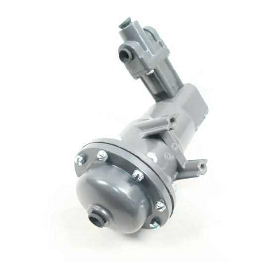
The 168 and 168H Series pneumatically operated
three-way snap-acting switching valves (figure 1) are
used to switch pressures on and off in response to a
predetermined change in an input signal pressure.
In operation, increasing pressure applied to the top of
the diaphragm through port D (see figure 2) moves the
stem and upper range adjusting nut toward the trip
lever. When the diaphragm pressure reaches the pre-
determined upper tripping pressure, the upper adjust-
ing nut pivots the trip lever to move the rocker assem-
bly to its alternate position, closing port C and opening
port B. When decreasing pressure to the diaphragm at
D reaches the lower tripping pressure, the spring
moves the stem and lower range adjusting nut to re-
turn the rocker to its original position, closing port B
and opening port C.
The 68 Series (figure 4) three-way snap-acting body
assemblies can be used alone, or to form the valve
body portions of 168 or 168H Series switching valves.
With the addition of the lever knob (key 11, figure 4) to
a Type 68-1 body assembly, a Type 68-2 manual
switching valve body assembly is formed.
Only personnel qualified through training or experience
should install, operate, and maintain these valves. If
there are any questions concerning these instructions,
contact your Fisher sales office or sales representative
before proceeding.
Installation
Maximum allowable pressures for the diaphragm and
body are given in tables 1 and 2 respectively. If pres-
sure to the unit is capable of exceeding these values,
install relief valves or other overpressure protection
devices in the pressure lines.
168, 168H, and 68 Series
W1932/IL
Figure 1. Exterior of 168 Series Switching Valve
DIAPHRAGM
DIAPHRAGM
SPRING
ROCKER
ASSEMBLY
B
A
C
BODY
BODY SPRING
TRIP LEVER
W0110-2/IL
Figure 2. Construction Details of 168 Series Switching Valve
D
UPPER RANGE
ADJUSTMENT
NUT
STEM
LOWER RANGE
ADJUSTMENT
NUT
Advertisement

Related Manuals for Fisher 168-1


Summary of Contents for Fisher 168-1
- Page 1 DIAPHRAGM SPRING Only personnel qualified through training or experience should install, operate, and maintain these valves. If there are any questions concerning these instructions, ROCKER contact your Fisher sales office or sales representative ASSEMBLY before proceeding. UPPER RANGE ADJUSTMENT STEM...
- Page 2 – – – – – – – – – – – – – – – – – – 10.3 1U878037022, metallic 68-2 168-1 2 to 60 0.1 to 4.1 1U877127142, green 10.3 1U878037022, metallic 68-1 168-2 2 to 40 0.1 to 2.8 1U879727142, yellow 10.3...
-
Page 3: With Manual Reset Switch
168 and 168H Series Manual Reset Because of the care Fisher takes in meeting all Operation manufacturing requirements (heat treating, dimension- al tolerances, etc.), use only replacement parts manufactured or furnished by Fisher. -
Page 4: Parts Ordering
168, 168H, and 68 Series Replacing 68 Series Body Assembly 2. Remove lever (key 20) and pin (key 22) from the stem protector. Inspect parts and replace as neces- Parts sary. 3. Insert pin in lever and replace lever in stem protec- Note tor, making sure the lever is in the proper position for the trip mode (see 168 or 168H Series Manual Reset... - Page 5 168, 168H, and 68 Series 43A8117-B B1199-1 / IL DU8774-D/DOC DU8796-D/DOC Figure 3. Switching Valve Constructions...
- Page 6 Figure 4. 68 Series Switching Valve Body Assemblies *Recommended spare part. Fisher, Fisher-Rosemount, and Managing The Process Better are marks owned by Fisher Controls International, Inc. or Fisher-Rosemount Systems, Inc. All other marks are the property of their respective owners.