Table of Contents
Advertisement
Advertisement
Table of Contents

Related Manuals for Dvorak ILD02 SG


Summary of Contents for Dvorak ILD02 SG
-
Page 1: Service Manual
SERVICE MANUAL SPIDER ILD02 SG SM-SG-2 Ev3/25062014... -
Page 2: Table Of Contents
SPIDER ILD02 SG TECHNICAL DESCRIPTION ................4 TECHNICAL SPECIFICATIONS ................. 4 1 Special service tools .................... 5 2 Troubleshooting ....................8 2 Basic technical specifications ................10 4 Regular maintenance SPIDER ................11 4.1 Daily ............................11 4.2 After first 8 hours ........................12 4.3 After 25 hours ........................ - Page 3 7.8 Carburetor solenoid ....................... 70 7.9 Fuses ............................. 71 7.10 Control panel ........................72 7.11 Battery ..........................72 7.12 Steering servomotor PAL827 ....................73 7.13 Servomotor of the drive control ..................73 7.14 Control unit NBB ........................ 74 7.15 Starter – starter relay ......................79 7.16 Clutch ..........................
-
Page 4: Technical Description
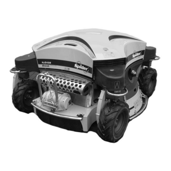
TECHNICAL DESCRIPTION The mower is a self-propelled machine with four-wheel drive, controlled by the transmitter (remote radio controller) signal. Its unique wheel-steering technology ensures a high manoeuvrability both on level ground and on slopes. The basic part of the machine is formed by a square solid frame, which is connected with a sliding frame. The middle part of the sliding frame carries all transmission parts such as the engine, the hydraulic pump, the hydraulic motor and the control unit. -
Page 5: Special Service Tools
1 SPECIAL SERVICE TOOLS Wooden block for lifted mower (400 x 200 x 200) – 2 pieces Straight lath for adjustment of wheel geometry (length 1300 mm) Engine oil filter release jig 5 / 84 SM-SG-2 Ev3/25062014... - Page 6 Hydraulic oil filter release spanner P/N PR001 P/N PR001 Wheel hub puller P/N PR002 Laser geometry adjustment tool P/N PR006 6 / 84 SM-SG-2 Ev3/25062014...
- Page 7 Ampere meter: CEM DT - 9701 Voltmeter: Ben electronic DT - 830 D+ 7 / 84 SM-SG-2 Ev3/25062014...
-
Page 8: Troubleshooting
2 TROUBLESHOOTING Problem Possible cause Correction Nothing appears on Replace the battery with a charged one the display when the RC battery is flat Charge the battery RC is turned on Insufficiently connected switch Switch on RC properly Charge the battery Check the Engine does not start Accumulator is discharged... -
Page 9: Replace Spark Plugs
Mower does not drive Ensure all tires are inflated to the same Check tyre pressure straight rate Geometry of the mower is out Adjust stabilizer length and wheel geometry One of the hydraulic motor is worn out Check or replace hydraulic motor Mow only grass which is maximum 3x taller Grass is overgrown, too high that the pre-set stubble height. -
Page 10: Basic Technical Specifications
2 BASIC TECHNICAL SPECIFICATIONS Wheel RPM/min Wheel RPM/min - wheels off the ground, blades off SPIDER turtle rabbit engine RPM hydr.oil temperature 70°C/158°F ILD02 56/min 110/min 3000 /min 10 / 84 SM-SG-2 Ev3/25062014... -
Page 11: Regular Maintenance Spider
4 REGULAR MAINTENANCE SPIDER 4.1 DAILY a) Check and add engine oil level dipstick Fig. 1 b) Check and clear engine and pump air intake screen Fig. 2 Fig. 3 c) Check blades mounting, sharpening and balancing Test of screw retightening Test of blade cutting edge Fig. -
Page 12: After First 8 Hours
d) Lubricate toothed segment and guide bushing of the cross - Interflon FIN LUBE Fig. 5 4.2 AFTER FIRST 8 HOURS a) Change engine oil - see 6.2 Replacement of the engine oil filter 4.3 AFTER 25 HOURS a) Clean rough air filter Rough air filter Fig. -
Page 13: After 50 Hours
4.4 AFTER 50 HOURS a) Clean paper air filter paper air filter Fig. 8 b) Lubricate steering chain - spray Interflon FIN LUBE TF CHAIN SPRAY Interflon FIN LUBE TF Fig. 9 c) Tighten steering chain Slackness ± 20 mm Chain slackness adjuster screws Fig. -
Page 14: After 100 Hours
d) Check hydraulic oil level Oil dipstick Fig. 13 Fig. 12 4.5 AFTER 100 HOURS a) Change engine oil b) Clean spark plugs c) Clean dust and dirt from cylinder and cylinder head fins d) Check tension of wheel driving chain - see 6.18 Adjustment and replacement of the wheel driving chain 4.6 AFTER 200 HOURS... - Page 15 b) Change paper air filter Paper air filter Fig. 15 c) Lubricate wheel arms and wheel bearings MOBILGREASE XHP 222 Greasers Fig. 16 d) Check and adjust valve clearance Valve Clearance (when cold) Inlet, Exhaust 0.10 - 0.15 mm (0.004 - 0.006 in.) Adjustment: Loosen the locknut [A] and adjusting bolt [B].
-
Page 16: Seasonal Period
g) Check or refill oil of angular gears – MOBILUX EP004 6.16 Replacement of the angle gear UNI M8 h) Lubricate wheel housing and steering chains – Interflon FIN LUBE TF 6.18 Adjustment and replacement of the wheel driving chain 4.7 SEASONAL PERIOD a) Change spark plugs NGK BPR4ES Spark plugs should be serviced every 100 hours or at least once per season. -
Page 17: Engine Maintenance Chart
5 ENGINE MAINTENANCE CHART ENGINE MAINTENANCE CHART: KAWASAKI FS691V 24 HP : Service more frequently under dusty conditions. 17 / 84 SM-SG-2 Ev3/25062014... -
Page 18: Instruction Manual Spider
6 INSTRUCTION MANUAL SPIDER 6.1 TILTING OF THE MOWER FOR MAINTENANCE Always disconnect battery and remove spark plug caps to prevent any injury Turn the wheel transmission housing in the direction which you will be tilting the mower to. Always tilt the mower control unit up in order to prevent the oil from leaking to the air filter and carburettor. Only tilt the mower for the time necessary for maintenance. -
Page 19: Replacement Of The Engine Oil Filter
6.2 REPLACEMENT OF THE ENGINE OIL FILTER Clean thoroughly the area around oil filter and filling neck Suck out the oil from the crankcase through the filling neck (or discharge the oil with a discharge screw when the mower is tilted) ATTENTION! The oil must not get under the engine in the clutch space – the belts might slip. -
Page 20: Replacement Of The Hydraulic Oil Filter
6.3 REPLACEMENT OF THE HYDRAULIC OIL FILTER Suck out the oil through the filling neck from the hydraulic tank Tilt the mower on side of the fuel tank Clean thoroughly lower part of the mower. (ATTENTION, dirt must not get in the hydraulic tank!) Undo the hydraulic filter lid (Spanner 63mm) Oil filter lid Fig. -
Page 21: Replacement Of The Hydraulic Pump
6.4 REPLACEMENT OF THE HYDRAULIC PUMP Suck out oil from the hydraulic tank Dismounting: Remove stabilizer on the left side for better access to the pump Remove the cooling fan guard Remove the cooling fan Remove fan cowling (3 screws of the pump head) 1 –... - Page 22 Bottom of the mower: Remove belt tensioning nuts and pulley front disk (ATTENTION! There is a screw lock in the pulley side!) Remove the belts from the pump pulley Remove the rest of the pump pulley by releasing of bolt no.2 and securing screw no.1 (Fig. 34) Remove the hydraulic pump by releasing of two bolts no.3 (Fig.
- Page 23 70Nm 60Nm Fig. 35 23 / 84 SM-SG-2 Ev3/25062014...
-
Page 24: Replacement Of The Auxiliary Drive Brake From S/N151
6.5 REPLACEMENT OF THE AUXILIARY DRIVE BRAKE Technical description: The auxiliary drive brake works on the principle of a band brake, where the braking band brakes the pulley of the hydraulic motor and consequently also the wheels. The brake is controlled by a brake cylinder, which is connected to the filling circuit of the hydraulic pump. - Page 25 Release the brake and secure it by means of securing pin Fig. 41 Release the tightening bolt of the hydromotor and both securing nuts M10 Fig. 42 Dismount the driving belts XPB1450LW from the hydromotor pulley and hydromotor pulley Fig. 43 Dismount the securing nuts M10 of the hydromotor (Fig.
- Page 26 Mounting: Put the brake bracket – complete to the cross – see Fig. Mount the brake strap through the brake bracket – complete, cross, hydromotor and tight them by means of two nuts M10 – don´t tight (Fig.42) Fig. 45 Tight two springs TR1660 of the brake lever and fix them by means of the securing pin Fig.
- Page 27 Mount the belts to the hydromotor pulley. By means of tightening bolt M8x55 tight belts XPB1450LW and secure the hydromotor by two nuts M10 (Torque – 45 Nm) Fig. 48 Mount the house 1SC06x0,7 to the throat XAL 12-1 / 14-1,5 of the brake cylinder (Torque – 45Nm) Fig.
- Page 28 Start the engine. After the engine is started the brake lever must tight the spring and release the hydromotor pulley. For correctly adjusted brake the holes of the brake bracket and brake lever must be in one line (Fig. 52). Adjust the correct position of the brake by screwing or unscrewing of the fork rod inside the brake cylinder and secure it with the securing nut on the fork rod (Fig.
- Page 29 undo self securing nuts M6 and remove both springs from the rear bracket undo both bolts M10x45 and pull cylinder out from the fork rod and from the bracket remove spring bracket by driving out a key Mounting: Install the spring bracket and secure it by the key Screw up a new cylinder to the bracket M10x45 29 / 84 SM-SG-2 Ev3/25062014...
- Page 30 Install both springs by using pliers and secure them by two self-securing nuts M6 Connect hydraulic hose Deaerate system by breather, see above Adjust braking function by the fork rod, see above b) Replacement of the brake lining Dismounting: Remove driving belts on the brake side, see 6.15 Replacement of the driving belts Undo both lock nuts of the hydraulic motor Pull out brake strap Fig.
- Page 31 Mounting: (Take the above steps in reverse order) Use a new split pins Fig. 22 and 6 31 / 84 SM-SG-2 Ev3/25062014...
-
Page 32: Replacement Of The Hydraulic Motor
6.6 REPLACEMENT OF THE HYDRAULIC MOTOR Dismounting: Hydromotor hoses (ATTENTION! The oil must not get on the V-belts!) Release tensioning screw (Fig. 56) Release nuts of the bolts of the hydraulic motor seating (Fig. 56, 58) Dismount the belts XPB 1450 Remove the pulley and hydraulic motor from the cross (Fig.s 56, 57) Hydraulic hoses Tensioning screw... - Page 33 Loctite the pulley bolt Fig. 59 Fig. 60 50Nm Fig. 61 33 / 84 SM-SG-2 Ev3/25062014...
-
Page 34: Replacement Of The Clutch Driving Belt B 1160
6.7 REPLACEMENT OF THE CLUTCH DRIVING BELT B 1160 Lift the mower up to the max. height of cut and tilt it to the side of the fuel tank! The belt B1160 is tensioned with the driven box pulley. To tension the belt, disasemble the box pulley and remove the required number of spacers Pulley spacers Dismounting:... - Page 35 Self-securing nuts ±10 mm Driving belt B 1160 Driving belt B 1160 Driving bearing box pulley Fig. 65 Fig. 66 35 / 84 SM-SG-2 Ev3/25062014...
-
Page 36: Replacement Of The Blade Driving Belt Spb 2410
6.8 REPLACEMENT OF THE BLADE DRIVING BELT SPB 2410 Lift the mower up to the max. height of cut and tilt it to the side of the fuel tank! Dismounting: Remove mowing blades, carrier cartridges, nylon bearing covers, clutch cover and belt covers (Fig.s 62, 63, Release a tensioning bearing box screws (Fig. -
Page 37: Replacement Of The Pump Driving Belt Good Year Bx 17X960
6.9 REPLACEMENT OF THE PUMP DRIVING BELT GOOD YEAR BX 17X960 Lift the mower up to the max. height of cut and tilt it to the side of the fuel tank! The belt BX 17x960 is tensioned with the pump pulley. To tension the belt, disasemble the pump pulley and remove the required number of spacers Dismounting: Remove left mowing blade, carrier cartridge and clutch cover (Fig. - Page 38 Mounting: Install the belt Good Year BX 17x960 Put the bolt 3 through spring 4 and screw through lock nut 2 a short way and then into nut 5. Tight the nut 2 then. Insert the feeler gauge through the adjustment hole between the clutch disc and the brake and check the clearance –...
- Page 39 Put on the clutch belt see 6.7 Replacement of the clutch driving belt B 1160 Put the mower back to operating position Start the engine and test the activation of the mowing mechanism (DON’T MOUNT THE BLADE) Activated clutch must not activate the brake ...
-
Page 40: Replacement Of The Bearing Boxes-Driven, Driving, Tightening
6.10 REPLACEMENT OF THE BEARING BOXES-DRIVEN, DRIVING, TIGHTENING Lift the mower up to the max. height of cut and tilt it to the side of the fuel tank! Dismounting: Remove belt SPB 2410 see 6.8 Replacement of the blade driving belt SPB 2410 Remove belt B 1160 see 6.7 Replacement of the clutch driving belt B 1160 Remove the bolts of the bearing box... -
Page 41: Replacement Of The Clutch
6.11 REPLACEMENT OF THE CLUTCH Dismounting: Remove left mowing blade, carrier cartridge and clutch cover, belts B 1160, BX 17x960 6.9 Replacement of the pump driving belt Good Year BX 17x960 6.7 Replacement of the clutch driving belt B 1160 Disconnect the battery Disconnect clutch cables and the FASTON plug (Fig. -
Page 42: Sharpening And Replacement Of The Blade
6.12 SHARPENING AND REPLACEMENT OF THE BLADE Dismounting: Disconnect the battery Lift the mower and tilt it to the side of the fuel tank! Use gloves when changing the blades Remove the blade bolt, blade washer and finally the blade Be careful when removing the bolt, the blade may fall to the ground Check the blade geometry: The blade mustn´t be twisted, bent or deformed... -
Page 43: Replacement Of The Steering Chain
6.13 REPLACEMENT OF THE STEERING CHAIN The exchange is necessary when the chain extension is too big and it cannot be adjusted any more (the first occurrence of this can be fixed by removing one chain-link) Exchange steps: Lift the mower so that the wheels must be off the ground and can turn freely Turn the wheels until the connecting link is between the electric motor and left wheel Fig. -
Page 44: Replacement Of The Steering Motor
After the aplication let´s it penetrate for 25 minutes then blow the rest out with pressurized air Check the wheel geometry see 6.23 Adjustment of the wheel geometry 6.14 REPLACEMENT OF THE STEERING MOTOR Dismounting: Lift the mower so that the wheels must be off the ground and can turn freely Disconnect the battery Disconnect the supply cables of the electric servomotor (Fig. -
Page 45: Replacement Of The Driving Belts
6.15 REPLACEMENT OF THE DRIVING BELTS Dismounting: Adjust the mower to the lowest mowing height Lift and support the mower (wheels off the ground) Release the by-pass valve on the pump 1 – 2 turns (Fig. 88) Secure the auxiliary brake in the manual override position see 6.5 Replacement of the auxiliary drive brake from S/N151 Release tensioning screw of the hydraulic motor (Fig. -
Page 46: Replacement Of The Angle Gear Uni M8
6.16 REPLACEMENT OF THE ANGLE GEAR UNI M8 Every 200 operating hours check the gear lubricant capacity and condition of the gear wheels Lift the Spider into a vertical position – over the fuel tank and with the angular gearboxes facing upwards Remove the lid of the angle gear (Fig. -
Page 47: Replacement Of The Wheel Suspension Arm
6.17 REPLACEMENT OF THE WHEEL SUSPENSION ARM Dismounting: Lift the mower (the wheels must be at least 150 mm off the ground) Remove the wheel suspensions Remove the belts and corner brackets see 6.15 Replacement of the driving belts Remove the stabilizer Release the chain tension adjuster Remove the steering clamp bushings-taper locks see 6.23 Adjustment of the wheel geometry... -
Page 48: Adjustment And Replacement Of The Wheel Driving Chain
6.18 ADJUSTMENT AND REPLACEMENT OF THE WHEEL DRIVING CHAIN Every 200 operating hours check the chain tension and lubrication to ensure smooth running Dismounting: Remove the wheel suspension cover – 8 capscrews M6 Remove the chain tensioner Remove the sprocket from the transmission shaft (Fig. 97) – MIND the key!!! Mounting: Install the chain onto the wheel sprocket (Roller chain 084-1 * MOFA 1/2“... -
Page 49: Replacement Of The Wheel Shaft
6.19 REPLACEMENT OF THE WHEEL SHAFT Dismounting: Remove the wheel (3 bolts holding the wheel) Undy the main wheel nut (Fig. 99) Remove the wheel hub (use wheel hub puller, if necessary heat up the hub for easier dismounting ), spacing ring and key Clean the wheel shaft (it must be able to slide through the bearings) Remove the wheel suspension housing cover, tensioning segment and the chain see... -
Page 50: Replacement Of The Wheel Housing
6.20 REPLACEMENT OF THE WHEEL HOUSING Dismounting: Remove the housing cover Remove the wheel shaft see 6.19 Replacement of the wheel Remove the small chain sprocket ( Fig. 103) Remove 2 countersunk screws no.1 (Fig. 103) , 3 capscrews no.3 (Fig. 104) Remove the wheel housing Mounting: (take the above steps in reverse order) Clean wheel housing contact surface... -
Page 51: Adjustment Of The Stabilizer Length
6.21 ADJUSTMENT OF THE STABILIZER LENGTH Adjust and fasten the left side to the minimum length (Fig. 105) Release the right side so that the arm can move freely (Fig. 106) Adjust the axes of the pulley, sliding bar and girder in one line using the laser geometry adjustment tool (Fig. -
Page 52: Replacement Of The Stabilizer - Pressed In
6.22 REPLACEMENT OF THE STABILIZER - PRESSED IN Dismounting: Lift the mower (the wheels must be off the ground) Undo both capscrews no.7 holding stabilizer eye – bracket no.5 Remove retaining ring 30 no.4 and pull off the stabilizer bracket from the stabilizer nylon bushing no.6 Remove stabilizer nylon bushing no.6 from the arm joint Mounting: Take the above steps in reverse order... -
Page 53: Adjustment Of The Wheel Geometry
6.23 ADJUSTMENT OF THE WHEEL GEOMETRY Lift the mower (the wheels must be off the ground) Adjust the wheels in a straight forward direction Release the clamp bushing-taper lock of the steering chain sprocket Release one of the grubscrew no.1(two turns) and remove second one (Fig. 109) ... -
Page 54: Replacement Of The Elevation Servomotor
6.24 REPLACEMENT OF THE ELEVATION SERVOMOTOR Dismounting: Adjust the mower to the minimum height-of-cut Disconnect the battery Disconnect the electric connector of the servo Release self locking nut and remove the pinion 14M Remove three countersunk screws (Fig. 115) Remove the servomotor Mounting: Take the above steps in reverse order Pinion... -
Page 55: Adjustment Of The Lift Pull Rods
6.25 ADJUSTMENT OF THE LIFT PULL RODS ATTENTION! The lock nuts have left and right hand threads!!! Right Left Fig. 117 6.26 REPLACEMENT OF THE GIRDER AND CROSS Dismount: Adjust the mower to the minimum height-of-cut Disconnect the battery Remove the following: controller bracket, choke button, elevation module-disconnect sensors, driving belts and hydraulic motors see 6.6 Replacement of the hydraulic motor, expansion tank, valve EDH, breather... - Page 56 Mounting: Pull the girder and cross onto the guide bars and place the toothed segment into the teeth of the sliding bar tooth in the 1 groove) (Fig. 119) Assemble the girder bolts, bolt sets, stabilizer stiffener, lift levers, valve EDH, expansion tank, controller bracket, choke button, elevation module, hydraulic motors and driving belts see 6.6 Replacement of the hydraulic motor...
-
Page 57: Replacement Of The Drive Control Servomotor Nbb
6.27 REPLACEMENT OF THE DRIVE CONTROL SERVOMOTOR NBB Lift the mower (the wheels must be off the ground) Dismounting: Disconnect the battery Disconnect the supply cables Remove the lever of the servomotor and the servomotor (Fig. 120) Mounting: Install the servomotor Install the connection bar on the pin of the pump lever and the pin of the servomotor Set the servomotor and hydraulic pump shafts to zero (central) position Install the lever on servomotor and fasten the self securing nut... -
Page 58: Replacement Of The Starter Switch Relay
6.28 REPLACEMENT OF THE STARTER SWITCH RELAY Disconnect the battery Disconnect the relay wiress Connect the earth wire under the relay fixing screw during aasembly Check: When the relay switches on, the voltage must be on both heavy-current relay connectors If not, check the relay control voltage of the supply wire (brown). -
Page 59: Replacement Of The Main Harness
6.29 REPLACEMENT OF THE MAIN HARNESS Disconnect the battery Disconnect the jointing sleeves of all parts: control unit, throttle control, carburettor solenoid, STOP button, horn, elevation module, charger, clutch, driving servomotor NBB, steering motor, starter relay, and control panel Remove the fuse box cover Undo the fuse box Starter relay Charger... -
Page 60: Carburettor Maintenance
6.30 CARBURETTOR MAINTENANCE Adjustment of the idle rpm – screw A (Fig. 123) behind the bracket Engine minimum revolutions – 1450rpm Engine working maximum revolutions – 2900 rpm are pre-set in Kawasaki Co. You can increase them by shortening of the spring (Fig. 124) if necessary Carburettor discharge screw (seasonal maintenance –... - Page 61 CARBURETTOR PARTS DIAGRAM 11061-7009 GASKET,CHAMBER 16014-7010 SCREW-PILOT AIR 11061-7010 GASKET,SCREW 16020-7003 CHAMBER-FLOAT 11061-7087 GASKET,INSULATOR 16025-7017 VALVE-THROTTLE 11061-7088 GASKET,INSULATOR/MANIFOLD 16030-7003 VALVE-FLOAT 11061-7093 GASKET,MANIFOLD 16031-7002 FLOAT 130AA0630 BOLT-FLANGED,6X30 16041-7050 SHAFT-CARBURETOR,CHOKE 13107-7018 SHAFT 16041-7051 SHAFT-CARBURETOR,THROTTLE 15004-7063 CARBURETOR-ASSY 16073-7013 INSULATOR 16186-7006 VALVE-ASSY-CHOKE 92009-2402 SCREW 172BA06115 BOLT-STUD,6X115 92063-7141 JET-MAIN,#122,3280FT 21188-7002 SOLENOID...
-
Page 62: Fuel System
6.31 FUEL SYSTEM CALIFORNIA VERSION ONLY - EVAPORATIVE EMISSION CONTROL SYSTEM The Evaporative Emission Control System is designed to store and dispose evaporative emissions from the gas tank and carburetor. A carbon canister is used to store the fuel vapors. The fuel vapors adhere to the carbon canister, until the engine is started, and engine vacuum can be used to draw the vapors into the engine, so that they can be burned along with the fuel/air mixture. - Page 63 Aluminium fuel tank Roll-over valve Carbon canister Engine purge port 63 / 84 SM-SG-2 Ev3/25062014...
-
Page 64: Hydraulic Diagram
6.32 HYDRAULIC DIAGRAM Hydraulic oil pressure: - nominal 100 bar - maximal 160 bar Activation – deactivation of auxiliary drive brake: - activation 0 bar - deactivation 6-7 bar 64 / 84 SM-SG-2 Ev3/25062014... -
Page 65: Torque
6.33 TORQUE Bolt material 480 – 680 580 – 780 780 – 980 980 – 1180 Material strength [MPa] 1180 - 1380 13,5 16,5 17,5 39,5 M 10 20,5 35,5 47,5 80,5 M 8x1 17,5 32,5 M 10x1,25 20,5 79,5 M 12x1,5 35,5 M 14x1,5... -
Page 66: Electrical System
7 ELECTRICAL SYSTEM 7.1 ELECTRICAL COMPONENT LOCATION Elevation EDH valve limit sensors Control unit NBB Skid steering sensor Starter, starter relay, connectors (clutch, charging and ignition) Elevation and skid steering module Elevation servomotors Main switch Emergency STOP Horn Fuses box Moving servomotor NBB Control... -
Page 67: Main Switch - Emergency Stop
7.2 MAIN SWITCH – EMERGENCY STOP Use like main switch of power supply. Check: If main switch is presed: contacts 1-2 switch off and 3-4 switch on. BLACK - control unit, starter, control panel BLUE - earth WHITE - ignition Main switch 7.3 HORN Characteristics: supply voltage = 12 V (+ red) -
Page 68: Skid Steering System
7.4 SKID STEERING SYSTEM The slope mower Spider ILD02 is equipped with a skid steering function. This function allows machine rotation around its vertical axis by driving two sets of wheels in opposite directions. This function can be activated by the skid steer button on the remote controller, provided the wheels are positioned in the straight driving driving direction. -
Page 69: Elevation Servomotor Connector
7.5 ELEVATION SERVOMOTOR CONNECTOR Servomotor connector Servomotor connector Current measuring 7.6 ELEVATION SYSTEM Servomotor characteristics: power supply = 12 V current drain (one motor) = 1 A (down) - 5 A (up) - by Spider loading Elevation servomotors are controlled by elevation and skid steering module with the help of two elevation limit sensors. -
Page 70: Engine Rpm Servomotor
7.7 ENGINE RPM SERVOMOTOR Used like a engine accelerator Characteristic: Power supply = 6 V control f = 50 Hz Earth-Black Power supply (+6V)-Red Control - Yellow Engine rpm servomotor 7.8 CARBURETOR SOLENOID electromagnetic valve to shut off fuel supply Characteristic: power supply = 12 V, current drain = 0,4A coil resistance... -
Page 71: Fuses
7.9 FUSES 5 A – control panel, skid steering power supply 15 A – alternator 15 A – alternator 20 A – logic, steering servo 20 A – logic, steering servo Fuses box When changing fuses strictly follow the electric current value for which the fuses are designed. Do not replace damaged fuses with fuses with a higher or lower rating. -
Page 72: Control Panel
7.10 CONTROL PANEL signaling + hour meter 1. Power indicator (shines green when power is on) 2. Signal reception (shines green if signal reception is correct) 3. Neutral position (shines green when neutral pos. is correct) 4. Blade (shines red when blade is engaged) Hour meter +12V (red) 1 +12V... -
Page 73: Steering Servomotor Pal827
7.12 STEERING SERVOMOTOR PAL827 Characteristic: Power supply 12V Wheels off the ground-max.steering load = 10A Wheels on the ground- max. steering load = 30 A Steering servomotor Steering servomotor Current measuring 7.13 SERVOMOTOR OF THE DRIVE CONTROL Characteristic: 12 V PAL Power supply: power supply = 12 V Control power: power supply = 12 V... -
Page 74: Control Unit Nbb
7.14 CONTROL UNIT NBB Characteristic: Transmission and reception frequency range 400 – 477 MHz When removing and reconnecting harness connector from/to the control unit be careful not to damage the contact pins in the connector Attention!! FOR SPIDER ILD02 ONLY USE control unit NBB02. Service plug Serial number Control unit NBB... - Page 75 LED 1 LED 2 LED 3 LED 4 !!!Attention!!!: During electro-welding on the machine, disconnect the receiver from the current supply! Otherwise there is a risk of damage to the receiver´s electronic system! 75 / 83 SM-SG-2 Ev3/25062014...
- Page 76 PROGRAMMING OF THE CONTROL UNIT SPIDER PARAMETER PROGRAM Getting Started: Ensure the power on the SPIDER is off Connect the programming cable between the NBB control unit (service plug) and your Computer Set the switch on the cable in the direction OFF or O (depends on the cable version) Switch on the power on the Spider Operating with Spider Parameter Program: Select the tab ”Com-Port settings”...
- Page 77 Default values: Recommended range: Zero position offset -5 +5 90 – 100 Maximum angle Minimum power offset 25-30 Zero range Contra signal Possible adjustments: Zero Position Offset To set an offset to the neutral (middle) position of the hydraulic servomotor. Maximum angle To set the limit (range) angle of the hydraulic servomotor –max.
- Page 78 Finish: After you have changed any parameter in the receiver, you can select the tab “Load/Save parameter“ to read all data from the NBB receiver and save them in a file. You can also load a parameter file and write that to the NBB receiver.
-
Page 79: Starter - Starter Relay
7.15 STARTER – STARTER SOLENOID Characteristic: Relay 12 V Control wire: switch on = 12 V and main wire voltage = 12 V Coil resistant = 4,1 ohm Earth Supply wire Control wire Starter wire (red) Starter solenoid 7.16 CLUTCH Characteristic: Switching voltage = 12 V Coil Resistance. -
Page 80: Charging And Ignition Cables
7.17 CHARGING AND IGNITION CABLES Charging: Voltage = 13,8 V Max. current = 13 A Ignition: Wire brings ignition down to earth via STOP button (If wire is disconnected or broken, is impossible to turn the engine off) Charging wire Current measuring Ignition wire Charging and ignition cables... -
Page 81: Nbb Electric Diagram Ild02
7.19 NBB ELECTRIC DIAGRAM ILD02 SG 81 / 83 SM-SG-2 Ev3/25062014... -
Page 82: Elevation And Skid Steering Module Nbb Ild02
7.20 ELEVATION AND SKID STEERING MODULE NBB ILD02 82 / 83 SM-SG-2 Ev3/25062014... -
Page 83: Enclosures - Service Bulletins
8 ENCLOSURES – SERVICE BULLETINS 8.1 ECOLOGICAL HYDRAULIC OIL Dvořák – svahové sekačky Bulletin: Service Bulletin s.r.o. Date: 1. 9. 2008 Dvorce 62, 58001 Havlíčkův Brod Informative Tel: +420 569 425 767 Ecological hydraulic oil Fax: +420 569 429 239 Info@spider-cz.com Informative Technical change, servicing not necessary...
Need help?
Do you have a question about the ILD02 SG and is the answer not in the manual?
Questions and answers