Table of Contents
Advertisement
Advertisement
Table of Contents

Subscribe to Our Youtube Channel
Summary of Contents for NexxTech 2211813
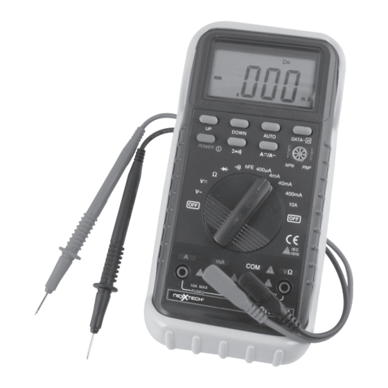
- Page 1 2211813 DUAL DISPLAY 29 AUTO RANGE DIGITAL MULTIMETER OPERATOR’S MANUAL...
-
Page 2: Table Of Contents
CONTENTS PAGE 1. Safety Information ................1.1 Introduction ................1.2 Usage ................1.3 Symbols ................1.4 Maintenance ................2. Description ................5-10 3. Operating Instructions ................3.1 Measuring Voltage ................3.2 Measuring Current ................3.3 Measuring Resistance ................3.4 Continuity Test ................ - Page 3 4. Specifications ................4.1 General Specifications ................4.2 DC Voltage ................4.3 AC Voltage ................4.4 DC Current ................4.5 AC Current ................4.6 Resistance ................4.7 Diode ................4.8 Audible Continuity ................4.9 Transistor ................5. Accessories ................5.1 Supplied with the multimeter ................
-
Page 4: Safety Information
1. SAFETY INFORMATION This multimeter has been designed according to IEC-1010 concerning electronic measuring instruments with an overvoltage category (CAT II) and pollution 2. Follow all safety and operating instructions to ensure that the meter is used safely and is kept in good operating condition. -
Page 5: Usage
1.2 USAGE • Never exceed the protection limit values indicated in specifications for each range of measurement. • When the meter is linked to a measurement circuit, do not touch unused terminals. • When the value scale to be measured is unknown beforehand, set the range selector at the highest position. -
Page 6: Symbols
1.3 SYMBOLS Important safety information, refer to the operating manual. Dangerous voltage may be present. Earth ground. Double insulation (Protection class II). -
Page 7: Maintenance
1.4 MAINTENANCE • Before opening the meter, always disconnect test leads from all sources of electric current. • For continue protection against fire, replace fuse only with the specified voltage and current ratings: F1: F 500mA/250V F2: F 10A/250A • If any faults or abnormalities are observed, the meter cannot be used and it has to be checked out. •... -
Page 8: Description
2. DESCRIPTION This meter is an auto ranging professional measuring instrument with 33/4 digit LCD, capable of performing functions: - DC voltage measurement (Auto Ranging) - AC voltage measurement (Auto Ranging) - DC current measurement - AC current measurement - Resistance measurement (Auto Ranging) - Diode test - Transistor test - Audible continuity test... - Page 9 1-7. Function Buttons 8. Transistor Testing Socket 9. Rotary Switch 10. V/Ω Input Jack 11. COM Input Jack 12. mA Input Jack 13. A Input Jack...
- Page 10 UP (Range Selecting Button) When this button is pushed, voltage ranges will change as: 400V 1000V 400mV Or resistance ranges change as: 400Ω 4kΩ 40kΩ 400kΩ 4MΩ 40MΩ DOWN (Range Selecting Button) When this button is pushed, voltage ranges will change as: 400mV 1000V 400V...
- Page 11 AUTO (Auto Ranging Button) When this button is pushed in manual ranging mode, the meter will return to be in auto ranging mode immediately and “AUTO” symbol will appear on the top of the LCD. DATA-H (Data Hold Button) When this button is pushed, the display will keep the last reading and “D-H” symbol will appear on the LCD until pushing it again.
- Page 12 POWER (Power ON-OFF Button) This button is used to turn the meter ON or OFF. In Order to extend the battery life, an Auto Power OFF function is provided. If no key-inputs happen around 30 minutes, the meter will be turned off automatically.
- Page 13 Function Red Lead Connection Input limits DCV / ACV V / Ω 1000V DC or 750V rms AC Ω V / Ω 250V DC or rms AC V / Ω 250V DC or rms AC V / Ω 250V DC or rms AC A / mA 500mA DC or rms AC µ...
-
Page 14: Operating Instructions
3. OPERATING INSTRUCTIONS 3.1 MEASURING VOLTAGE 1. Connect the black test to the COM jack and the red test lead to the V/Ω jack. 2. Set the function switch at V or V ~ range to be used and connect test leads across the source or load under measurement. -
Page 15: Measuring Resistance
3. Connect test leads in series with the load in which the current is to be measured. 4. Read LCD display. The polarity of red lead connection will be indicated when making a DC measurement. 3.3 MEASURING RESISTANCE 1. Connect the black test lead to the COM jack and the red test lead to the V/Ω jack. (NOTE: The polarity of the red lead connection is positive “+”) 2. -
Page 16: Continuity Test
3. When checking in-circuit resistance, be sure the circuit under test has all power removed and all capacitors fully discharged. 3.4 CONTINUITY TEST 1. Connect the black test lead to the COM jack and the red test lead to the V/Ω jack. (NOTE: The polarity of red lead connection is positive “+”) 2. -
Page 17: Testing Transistors
3. Connect the red lead to the anode of the diode to be tested and the black lead to the cathode. Read LCD display to get the forward voltage drop of the diode under testing. 3.6 TESTING TRANSISTORS 1. Set the function switch at hFE position. 2. -
Page 18: General Specifications
4.1 GENERAL SPECIFICATIONS Max. Voltage Between Terminals and Earth Ground 1000V dc or 750V rms ac (sine) Fuse Protection A, mA: F 500mA/250V A:F 10A/250V µ Power Supply 9V NEDA1604 6F22 006P Display LCD, 3999 counts max., updates 2-3/sec Measurement Method Dual slope integration A/D converter Ranging Method Auto/Manual... -
Page 19: Dc Voltage
4.2 DC VOLTAGE Range Resolution Accuracy 400mV 0.1mV ± 0.8% of rdg ± 2 digits ± 0.5% of rdg ± 2 digits 10mV ± 0.5% of rdg ± 2 digits 400V 0.1V ± 0.5% of rdg ± 2 digits 1000V ±... -
Page 20: Ac Voltage
4.3 AC VOLTAGE Range Resolution Accuracy 400mV 0.1mV ------- ± 0.6% of rdg ± 0.2% of full scale ± 3 digits 10mV ± 0.6% of rdg ± 0.2% of full scale ± 3 digits 400V 0.1V ± 0.6% of rdg ± 0.2% of full scale ± 3 digits 750V ±... -
Page 21: Dc Current
4.4 DC CURRENT Range Resolution Accuracy ± 0.8% of rdg ± 2 digits µ µ ± 0.8% of rdg ± 2 digits µ 40mA ± 0.8% of rdg ± 2 digits µ 400mA 0.1mA ± 1.2% of rdg ± 2 digits ±... -
Page 22: Ac Current
4.5 AC CURRENT Range Resolution Accuracy A (0-200 ± 0.8% of rdg ± 0.4% of full scale ± 3 digits A (201-300 ± 2.5% of rdg ± 0.4% of full scale ± 3 digits A (301-400 ± 8.0% of rdg ± 0.4% of full scale ± 3 digits ±... -
Page 23: Resistance
4.6 RESISTANCE Range Resolution Accuracy ± 0.8% of rdg ± 3 digits Ω Ω 4kΩ ± 0.8% of rdg ± 1 digits Ω 40kΩ ± 0.8% of rdg ± 1 digits Ω 400kΩ 100Ω ± 0.8% of rdg ± 1 digits 4MΩ... -
Page 24: Diode
4.7 DIODE Function Resolution Test Current Open Circuit Voltage 3.0V µ 4.8 AUDIBLE CONTINUITY Function Description Built in buzzer will sound, if resistance is lower than 50Ω. 4.9 TRANSISTOR Function Range Base Current 1 to 1000 3.0V µ -21-... -
Page 25: Accessories
5. ACCESSORIES 5.1 SUPPLIED WITH THE MULTIMETER Test Leads Electric Ratings 1500V, 10A MASTECH HYTL-060 Operating Manual HYS004241 Holster HYHT-60 5.2 HOW TO USE THE HOLSTER The holster can be used to protect the meter as well as providing a stand to improve viewing angle. - Page 26 b. Support the meter with a shallow angle using the small stand. c. Hang the meter on the wall using the small stand. Change the viewing angle by using the large stand and removing small stand. d. Holds test leads. -23-...
-
Page 27: Battery And Fuse Replacement
6. BATTERY AND FUSE REPLACEMENT If the sign “BATT” appears on the LCD display, it indicates that the battery should be replaced. Remove screws on the back cover and open the case. Replace the exhausted battery with a new battery. Fuses rarely need replacement and blow usually as a result of incorrect use. - Page 28 (or other proof of the original • Orbyx Electronics, LLC (”Orbyx”), as the distributor of purchase date) and a description of the defect(s). this Nexxtech product (your “Product”). What Does This Warranty Not Cover? What Does This Warranty Cover? •...
- Page 29 LIMITED WARRANTY ORBYX ELECTRONICS WARRANTY • Defacing the serial number, or using your Product for Distributed exclusively in ORBYX Electronics warrants that this product will be free from commercial or institutional purposes, voids this warranty. the U.S. by defects in materials and workmanship for a period of ninety (90) Are There Other Warranties? Orbyx Electronics, LLC days from the date of purchase.
Need help?
Do you have a question about the 2211813 and is the answer not in the manual?
Questions and answers