Advertisement
Quick Links
Advertisement

Related Manuals for Balt Split-Level-36


Summary of Contents for Balt Split-Level-36
- Page 1 Split-Level-36 Task Table Assembly Instructions...
- Page 2 Split-Level-36 Task Table Part Drawing Description Part Drawing Description Monitor Platform 1 EA CPU Rail 1 EA CPU Foot 2 EA Keyboard Platform 1 EA CPU Platform 1 EA Upper Insert 2 EA Hardware List Left Front & Right Back 9/16”Socket Screw...
-
Page 3: Assembly Diagram
Split-Level-36 Assembly Diagram HROUGH NSTRUCTIONS FROM BEGINNING BEFORE TO END STARTING TO ASSEMBLE UNIT Identify and Separate all the Parts and Hardware. Place the Monitor Platform (P1) with the insert nuts facing up. Attach 1 each Upper Insert (P3) and 1 each Upper Insert (P4) using 4 each (B) screws. - Page 4 Place the Keyboard Platform (P2) with Illustration # 3 the insert nuts facing up. Attach 1 each Upper Insert (P3) and 1 each Upper Insert (P4) using 4 each (B) screws. (Finger tighten only) Attach Crossbrace (P6) to the Upper Inserts (P3 & P4) using 2 Screws (A1) as shown in illustration #3.
- Page 5 11.) Place the CPU Platform (P10) with the insert nuts facing up. Attach 2 each CPU Feet (P9) using 4 each (A2) screws. (Finger tighten only) Attach 1 each CPU Rail (P8) to the CPU 12.) Platform (P10) using 2 each (A1) screws. (Finger tighten only) Attach 2 each Glides (F) to the 2 Feet (P9) 13.)
- Page 6 Sleeve Important The Balt product you have purchased is guaranteed against material and workmanship defects. This guarantee extends 1 year from date of purchase. Should this product fail to function satisfactorily under normal use due to defect or imperfection, the defective part or product will be replaced. Damage caused by common carriers during shipment is not included in this guarantee.
-
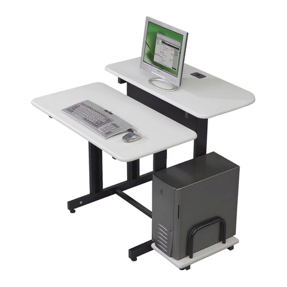
Page 7: Task Table
Split-Level-36 Task Table For more information 1-800-749-2258 Adjustable Height 25 ½ - 31 ½ 8¾ Shipping Information 2.8 Cubic Feet 35 lbs. Carton 1 5½” 36” 24” splitlevel - 12/07/01...
Need help?
Do you have a question about the Split-Level-36 and is the answer not in the manual?
Questions and answers