Table of Contents
Advertisement
Advertisement
Table of Contents

Related Manuals for Coway CHP-06EL


Summary of Contents for Coway CHP-06EL
-
Page 3: Table Of Contents
Table of Contents 1. Precaution 1-1 Precautions on electricity ................1-2 Precautions on installation ................1-3 Precautions on use ..................1-4 Precautions on services ................. 2. Product characteristics and specifications 2-1 Product characteristics ................... 2-1-1 Product characteristics ................ 2-1-2 Characteristics of major parts .............. 2-2 Major specifications .................. - Page 4 5-2-2 Basic specifications ................5-2-3 Major functions ..................6. Exploded view of the system and the list of service parts 6-1 Exploded view and parts list of CHP-06EL ............ 6-2 Service parts list of CHP-06EL ............... 7. Parts location diagrams 7-1 Electrical wiring diagram ................
-
Page 5: Precaution
- Otherwise electric shock or fire may occur as a result. 11. If the electric outlet is wet, carefully unplug the unit and let the electric outlet completely dry before subsequent use. - Otherwise electric shock or fire may occur as a result. Coway co., Ltd... -
Page 6: Precautions On Installation
5. Use tap water as feed water. 6. Proper places to install the unit - Install the unit firmly on a level area. If the unit is installed in an unstable place, the system may not function properly. Coway co., Ltd... -
Page 7: Precautions On Use
6. Do not exert excessive shock on the product. 7. When cleaning the water tank, use the multi cock in front of the product and hot water drain to drain the water from the cold water tank and hot water tank. Coway co., Ltd... -
Page 8: Precautions On Services
- Otherwise, product malfunction, short circuit, or fire may occur as a result. 3. Connect the electricity and check that the unit operates properly before let the consumer use the product. - Make sure to inform the consumer of the malfunction and repair details. Coway co., Ltd... -
Page 9: Product Characteristics And Specifications
Prevention of Fine Dust - By using “Fine Post Carbon Filter”, it diminished the fine dust which can be flowed into the water tank. Coway co., Ltd... -
Page 10: Characteristics Of Major Parts
142W, AC 220V / 50Hz Volts: DC 24V Feed Valve AMPS: 210mA Volts: DC 24V N.O.S Valve AMPS: 210mA Possible manual reset Bi-Metal AC 220V, OFF: 88°C, ON: Manual reset temperature: 84°C or lower Heater 430W, AC 220V Coway co., Ltd... -
Page 11: Major Specifications
7.9 L/hr (25°C,1.4kgf/cm Product dimensions 260 (W) x 448 (D) x 1150 (H) mm Product weight 27kg There may be some discrepancies in the actual water-purifying quantity depending on the water temperature in season (Spring/fall, summer, and winter). Coway co., Ltd... -
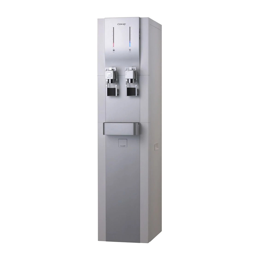
Page 12: Appearance And Dimensions
Product characteristics and specifications 2-3 Appearance and dimensions CHP-06EL [260 (W) x 448 (D) x 1150 (H) mm] Coway co., Ltd... - Page 13 Product characteristics and specifications Coway co., Ltd...
- Page 14 MEMO Coway co., Ltd...
-
Page 15: Product Installation
Product installation 3. Product installation 3-1 Installation materials 3-1-1 Parts Accessories Items Remark Drain hose Cooling Stopper Coway co., Ltd... -
Page 16: Installation Method
Install the system on a firm, level ground. Installation water pressure - CHP-06EL: The water purification system provides specified water quantity in a normal condition with the feed water pressure of 20 psi or higher. Installation distance from tap water supply - Feed water pressure below 20 psi: Install the system in a place within a range of 3M in height and 5M in distance. -
Page 17: Installing The Product
Product installation 3-2-2 Installing the product Main water supply valve 2 cooling stopper Inlet tubing (Orange) Outlet tubing (Blue) Coway co., Ltd... - Page 18 Flush water through each filter at least 5 minutes before Connection. 1) Connect it to voltage rating that matches it on the rating plate. Then, open the feed valve to supply water to the filtration system. PLUG Coway co., Ltd...
-
Page 19: Using The Product After Installation
1) To drink room water. - Turn the cold/room water changeover faucet to the right and press the cup-touch lever of the cock to extract room water. Coway co., Ltd... - Page 20 - Empty the gutter regularly so that it does not overflow. 1) Regular filter replacement and management is needed. - To drink clean water, clean and replace filter regularly. Replace filter at the estimated time of filter replacement. Coway co., Ltd...
-
Page 21: Disassembling And Refitting
Exercise caution not to damage or deform any parts when disassembling the system. Refit the system in the reverse order of disassembling. 4-1-2 Necessary tools Tool Tool name ‘+’ Cross-head screwdriver ‘-’ Flat-bladed screwdriver Nipper Adjustable spanner Coway co., Ltd... -
Page 22: Draining Water Before Disassembling The Product
4-2 Draining water before disassembling the product 4-2-1 Draining water Part name Explanation Reference picture Drain 1) Open the drain door and then connector open the drain connector. Drain hose 1) Connect the drain hose and then drain the hot water. Coway co., Ltd... - Page 23 Disassembling and refitting Part name Explanation Reference picture Drain hose 1) Connect the drain hose to the Cold water/Purified water cock levers. 2) Drain the Cold water/Purified water by pulling up the lever. Coway co., Ltd...
-
Page 25: Separating The Front Upper Part
1) Remove the 2 screws from the assy back of the front upper part. : 2 screw tappings (THT2, 4x10, MSWR, Ni-P) 2) Remove the front upper assy by lifting it upward. 3) Separate the connector to the front upper assy. Coway co., Ltd... - Page 27 Disassembling and refitting Part name Explanation Reference picture Filter 1) Separate the fittings to each filter and remove the filters. Auto daily 1) Separate the auto daily life water life water controller from the Membrane controller filter. Coway co., Ltd...
- Page 30 : 2 screw tapping (THT2, 4x10, MSWR, Ni-P) 2) Separate the 3 fittings connected to each tank and take out the silicon hose. 3 ) Separate the cock bracket assy in the direction of the arrow. 4-10 Coway co., Ltd...
- Page 31 1) Separate the low water level sensor sensor (yellow) and full water level sensor (red) by undoing the two fixing nuts using an adjustable spanner. Overflow 1) Remove the 2 rubber tubes sensor and then separate the overflow sensor. Coway co., Ltd 4-11...
- Page 32 MEMO 4-12 Coway co., Ltd...
-
Page 33: Fault Diagnosis
FND cable Check the FND cable and connection cable open? connection fault. replace it if necessary. Is the Check the main PCB and voltage of the PCB micom PCB power circuit defect. replace it if necessary. DC 5V? Coway co., Ltd... - Page 34 Compressor operating condition 1) Cold water selection switch ON 2) Cold water temperature 7.3°C or higher In the compressor operating The main PCB is Checking and replacing condition, is the voltage AC 220V abnormal. the main PCB generated? Coway co., Ltd...
- Page 35 Is the heater If the measurement value Replace the heater. resistance the rated value is off the specification, the (23.25Ω)? heater is faulty. Is the PCB Check the PCB and voltage AC 220V ? replace it if necessary. Coway co., Ltd...
-
Page 36: Control Specifications
Electrical wiring diagram 5-2-2 Basic specifications 1. Scope of application This control specification is for the electronic control devices applied to Coway’s Cold/Hot water purification system (CHP-06E). 2. Operating conditions 1) Power: AC 220V, 50Hz 2) Surrounding temperature: -20˚C - +70˚C (storage), ˚C - +50˚C (use) - Page 37 - Feed water valve 1 POINT - Feed water NOS valve 1 POINT - Auxiliary memory device (EEPROM) 3 POINT - Overflow sensor output 1 POINT 3) Operation part and indication part 1 Indication Part 2 Operation Part Coway co., Ltd...
-
Page 38: Major Functions
How water control function (Heater control) 1. When the hot water selection switch is on, the heater is controlled according to the water level and hot water temperature. 1) Heater-on temperature: 88°C (19.833kΩ) or lower 2) Heater-off temperature: 93°C (16.845kΩ) or higher Coway co., Ltd... - Page 39 70°C (37.307kΩ) 65°C (44.856kΩ) 60°C (54.165kΩ) Hot water selection switch is on → it is on all the time. 5. HOT level control specification Hot water temperature Heater control Remark 88°C or lower 19.833kΩ 93°C or higher 16.845kΩ Coway co., Ltd...
- Page 40 2) The On/Off control specifications according to the colt water segment are as the following: COLD segment Remark 4.5°C (130.351kΩ) 6°C (121.291kΩ) 7°C (115.647kΩ) 9°C (105.224kΩ) 10°C (100.412kΩ) 13°C (87.392kΩ) 14°C (83.48kΩ) 17°C (72.866kΩ) Cold water selection switch is on → It is On all the time. Coway co., Ltd...
- Page 41 - The control temperature can be increased by 0.5°C (≒3.0kΩ) by cutting the C/T UP jumper. 2) Decreasing the control temperature - The control temperature can be decreased by 0.5°C (≒3.0kΩ) by cutting the C/T DOWN jumper. Coway co., Ltd...
- Page 42 - Feed valve OFF, NOS valve ON. (See ‘Water overflow sensing operation’) 3. Low/full water level sensing and delay time 1) When OPEN or SHORT is inputted for 3 seconds or more, the normal value is recognized and the operation starts. 5-10 Coway co., Ltd...
- Page 43 3. Water overflow detecting time is cancelled. (The 20-second delay time is eliminated with the shortened time function in the test mode.) 3. The test mode is cancelled 30 minutes later and the system operates in normal mode. Coway co., Ltd 5-11...
- Page 44 94.521 144.354 124.827 108.236 11.4 94.084 143.650 124.230 107.727 11.5 93.649 142.949 123.636 107.221 11.6 93.217 142.253 123.045 106.718 11.7 92.786 141.560 122.457 106.217 11.8 92.359 140.871 121.873 105.719 11.9 91.933 140.186 121.291 105.224 12.0 91.509 5-12 Coway co., Ltd...
- Page 45 66.7 42.112 69.7 37.718 72.7 33.833 60.8 52.540 63.8 46.914 66.8 41.956 69.8 37.580 72.8 33.712 60.9 52.340 63.9 46.739 66.9 41.802 69.9 37.444 72.9 33.591 61.0 52.142 64.0 46.564 67.0 41.647 70.0 37.307 73.0 33.470 Coway co., Ltd 5-13...
- Page 46 92.7 17.011 95.7 15.426 98.7 14.006 86.8 20.702 89.8 18.723 92.8 16.956 95.8 15.376 98.8 13.961 86.9 20.632 89.9 18.661 92.9 16.900 95.9 15.326 98.9 13.917 87.0 20.563 90.0 18.599 93.0 16.845 96.0 15.276 99.0 13.872 5-14 Coway co., Ltd...
- Page 47 MEMO Coway co., Ltd 5-15...
-
Page 48: Exploded View Of The System And The List Of Service Parts
6. Exploded view of the system and the list of service parts 6-1 Exploded view and parts list of CHP-06EL This document is Coway’s technical property. Only the person approved by the company may use this document. Coway co., Ltd... - Page 49 Post Carbon comple x filter 14 inch Main tank insulation-Rear Filter bracket assy Separate board Drain connector assy Main tankcap assy Main PBA assy Top cover assy Caster Main tank insulation-Front Base plate Side cover L assy Booster pump Coway co., Ltd...
-
Page 50: Service Parts List Of Chp-06El
Exploded view of the system and the list of service parts 6-2 Service parts list of CHP-06EL Code No. Description Specification Q’ty Remark 100754 Neo Sense filter 14 inch For export production For export production, normal 50 GPD, 100777 Membrane filter (RO) 14 inch... - Page 51 Assy 3105838 Cold cock assy (CHP-06E, export) Assy 3202254 Lever rubber (CHP-06E) SILICON, BLACK (hardness 50) 3105839 SMPS assy (CHP-06EL) 10W assy, CHP-06EL Base connector assy - hot water 3105841 Assy (CHP-06E) Hot water safety cock assy 3105842 One touch...
- Page 52 Exploded view of the system and the list of service parts Code No. Description Specification Q’ty Remark 3105846 FEED-NOS valve cable (CHP-06E) UL 1007 22AWG 3105847 Cold water silicon insulation (CHP-06E) 23(ID)X33(OD)X50(L) 3105850 Main tank insulation (CHP-06E) 200x80, 3t Coway co., Ltd...
-
Page 53: Parts Location Diagrams
Parts location diagrams 7. Parts location diagrams 7-1 Electrical wiring diagram This document is Coway’s technical property. Only the person approved by the company may use this document. Coway co., Ltd... -
Page 54: Cable Specification
► FND cable Pay attention to the connecting direction. (Connection) ► FND connection cable Pay attention to the connecting direction. (Connection) ► Heater cable Fix the insulation tube as close as possible to the left housing. Coway co., Ltd... - Page 55 Parts location diagrams ► FEED-NOS valve cable (Connection) ► KEY PCB cable Pay attention to the connecting direction. (Connection) ► Overflow sensor cable Connect in series. Must be rubber cap assy. Coway co., Ltd...
- Page 56 ► Power cord connection cable Pay attention to the connecting direction. (Connection) Contraction (Connection) Fix the insulation tube as close as possible to the left housing. Fix the ferrite core as close as possible to the right-hand housing. Coway co., Ltd...
-
Page 57: Water Piping Diagram
Parts location diagrams 7-3 Water piping diagram Coway co., Ltd... -
Page 58: Pba Location Diagram
Parts location diagrams 7-4 PBA location diagram 7-4-1 MAIN 1 2 3 4 Coway co., Ltd... - Page 59 4 CN11 (Cold sensor) ! CN5 (Heater) 5Vdc Pin No. Signal Pin No. Signal 240Vac 240Vac Signal 24Vdc @ CN6 (Comp.) 5 CN12 (Over Flow sensor) 5Vdc Pin No. Signal Pin No. Signal 240Vac Signal 240Vac Signal Coway co., Ltd...
-
Page 60: Button Switch
Parts location diagrams 7-4-2 BUTTON SWITCH 1 CN1(KEY ↔ MAIN) Pin No. Signal Signal (HOT S/W) Signal (COLD S/W) Coway co., Ltd... -
Page 61: Smps L Type
Parts location diagrams 7-4-3 SMPS L TYPE Coway co., Ltd... - Page 62 Parts location diagrams 1 CN2 (DC POWER OUTPUT) 2 CN1 (240Vac POWER INPUT) Pin No. Signal Pin No. Signal 240Vac 5Vdc 240Vac 24Vdc 24Vdc 7-10 Coway co., Ltd...
-
Page 63: Circuit Diagrams
Circuit diagrams 8. Circuit diagrams 8-1 MAIN This document is Coway’s technical property. Only the person approved by the company may use this document. Coway co., Ltd... -
Page 64: Button Switch
Circuit diagrams 8-2 BUTTON SWITCH This document is Coway’s technical property. Only the person approved by the company may use this document. Coway co., Ltd... -
Page 65: Smps L Type
Circuit diagrams 8-3 SMPS L TYPE This document is Coway’s technical property. Only the person approved by the company may use this document. Coway co., Ltd... - Page 66 MEMO Coway co., Ltd...
-
Page 67: Reference Information
Reference information 9. Reference information 9-1 Names of each part ► Front view Operation Part Cold/Room Water Changeover Faucet Water faucet Cup-touch Lever Indication Part Hot Water Safety Faucet Gutter Front Draining Door (Hot water) Front cover Foot Coway co., Ltd... - Page 68 Reference information ► Rear view Top Cover Radiator Cooling Stopper Outlet(Blue) Inlet(Orange) Power Cord PLUG Rear cover Coway co., Ltd...
-
Page 69: Functions And Reference Information
The more lamp on the indicators, the more cold Temperature Indicator water. When selecting hot water mode, the indicator Hot water mode lamp lamps are on. When selecting cold water mode, the indicator Cold water mode lamp lamps are on. Coway co., Ltd... - Page 70 When using hot water selection mode button, selection button check if the hot water mode lamp turns on. Cold water mode When using cold water selection mode button, selection button check if the cold water mode lamp turns on. Coway co., Ltd...
-
Page 71: Types And Functions Of Filters
It also minimizes the contamination in the water tank by decreasing the fine carbon particles. Ceramic Filter - Material: Topcera antibacterial ceramic - Characteristics: It suppresses proliferation of micro organisms in the water tank, enhancing the hygiene and water taste. Coway co., Ltd... -
Page 72: The 5-Step Water Filtering System
5-Step: CERAMIC FILTER Restraints propagation of the microorganism inside water tank and enhances sanitation. Disposal Water Outlet NEO-SENSE CERAMIC FILTER FINE POST FILTER CARBON FILTER MEMBRANE FILTER (RO) Coway co., Ltd... -
Page 73: Toto Services
- This reverse osmosis system contains a replacement treatment component critical for the effective reduction of total dissolved solids, and that the product water shall be tested periodically to verify that the system is performing properly. Coway co., Ltd... -
Page 74: Replacing Filters
1) Lift up the front drain door and then remove the fixing screw using a cross-head screwdriver. Separate the lower cover by pulling it down and forward. Coway co., Ltd... - Page 75 Clean the Neo Sense filter for about 30 seconds before installing it. - When replacing the Fine Post Carbon Filter: Clean the Fine Post Carbon Filter for about 30 seconds with the water coming from the Neo Sense filter before installing the filter. Coway co., Ltd...
-
Page 76: Cleaning And Maintenance
Extract the cold/room water in the water tank through the tap of the cold/room water faucet and empty the water in the hot water tank through the front drainage Draining out the hot water tank 9-10 Coway co., Ltd... - Page 77 (6 areas) of the water tank. Then take out the hose and open the cover of the storage tank. 1) Separate the ceramic filter from the bottom of the storage tank cover and clean it into room water. Coway co., Ltd 9-11...
- Page 78 1) Wipe the inside of storage tank with a soft cloth. 1) Wash out the storage tank with the reserved water and drain it through the drain hose. Draining out the cold/room water tank Draining out the hot water tank 9-12 Coway co., Ltd...
- Page 79 2 seconds for re-operation. Please close the cover of the storage tank completely. - Ants or other substances might get inside. Coway co., Ltd 9-13...
- Page 80 - It is easily disassembled by holding the gutter after removing the gutter cover. 1) Installing the gutter - After adhering the gutter closely to the front side of the product and slightly raise the gutter cover. 9-14 Coway co., Ltd...
- Page 81 MEMO Coway co., Ltd 9-15...
- Page 82 MEMO 9-16 Coway co., Ltd...
Need help?
Do you have a question about the CHP-06EL and is the answer not in the manual?
Questions and answers