
Related Manuals for ABB Tropos 1410


Summary of Contents for ABB Tropos 1410
-
Page 1: Installation Guide
® Tropos Installation Guide Models 1410 and 1410-HAZ 555 Del Rey Ave. Sunnyvale, CA 94085 USA www.abb.com/tropos 408-331-6800 Part No. 200437-00 Rev B0 2012_11_17... -
Page 2: Copyright Notice
The required antenna impedance is 50 ohms. Operation is subject to the following two conditions: This device may not cause interference, and This device must accept any interference, including interference that may cause undesired operation of the device. Tropos 1410 Installation Guide... - Page 3 (EIRP) is not more than that permitted for successful communication. CSA Notice The Tropos 1410-HAZ is certified for use in Class I, Division 2, Groups A, B, C, D Hazardous Locations. Such locations are defined in Article 500 of the National Fire Protection Association (NFPA) publication NFPA 70, otherwise known as the National Electrical Code.
- Page 4 European Community Language Versions of Informal Statement for Inclusion in User Information The following statements are in accordance with Article 6.3 of Directive 1999/5/EC. 1410 1410 1410 1410 1410 1410 1410 1410 1410 1410 1410 1410 1410 1410 Tropos 1410 Installation Guide...
-
Page 5: Important Safety Instructions
Tropos 1410 Installation Guide... - Page 6 être effectuées uniquement par du personnel qualifié. The Tropos 1410s are installed in wet, outdoor locations. Make sure closure caps are installed and all cable connections are securely fastened and waterproofed. Surfaces may become hot. Use caution when accessing the Tropos 1410s. Tropos 1410 Installation Guide...
-
Page 7: Table Of Contents
2 Installing the Tropos 1410 ........ -
Page 8: Tropos 1410 Installation Guide
Index ............61 Tropos 1410 Installation Guide... -
Page 9: Tropos 1410 Installation Guide
Figures Figure 1 Tropos 1410 Exploded View - Front View ....14 Figure 2 Tropos 1410 Exploded View - Back View ....15 Figure 3 Example Mounting Approach - Antennas Facing Upward . - Page 10 Table 1 Tropos 1410 Models ........
-
Page 11: Introduction
Ethernet clients to a Tropos mesh network or to any 802.11 b/g/n access point. In the router configuration, the Tropos 1410 functions as a node in a Tropos mesh network as well as providing connectivity for wired serial or Ethernet clients and for 802.11 b/g/n wireless clients. -
Page 12: Installing The Tropos 1410
Installing the Tropos 1410 This guide explains how to install the Tropos 1410 safely and is intended for trained technical professionals. This chapter covers the following topics: “Product Summary” on page 13 “Preparing for Installation” on page 13 “Mounting Strategies”... -
Page 13: Product Summary
Tropos 1410-HAZ router (FCC) Preparing for Installation The Tropos 1410 must be installed by a trained professional, value added reseller, or systems integrator who is familiar with RF planning issues and regulatory limits defined by the governing body of the country in which the unit will be installed. This section explains how to prepare the installation site. -
Page 14: Figure 1 Tropos 1410 Exploded View - Front View
Chapter 2 Tropos 1410 Exploded View - Front View Figure 1 Serial port Ethernet port Clamp Tropos 1410 Pole bracket Tropos 1410 Installation Guide... -
Page 15: Figure 2 Tropos 1410 Exploded View - Back View
Chapter 2 Tropos 1410 Exploded View - Back View Figure 2 Pole bracket Tropos 1410 Clamp Tropos 1410 Installation Guide... -
Page 16: Installation Hardware And Tools
NEC code. The following distance limits apply to installations that have 10/100 Base-T Category 5 network cables attached to the Tropos 1410: 300 feet maximum between devices for 100BaseT operation 500 feet maximum for 10BaseT operation. -
Page 17: Location Guidelines
Building materials—Radio penetration is influenced by the building material used in construction. For example, drywall construction permits greater range than concrete blocks. Safety Installing the Tropos 1410 can pose a serious hazard. Be sure to take precautions to avoid the following: Exposure to high voltage lines during installation... -
Page 18: Figure 3 Example Mounting Approach - Antennas Facing Upward
Chapter 2 Note To eliminate potential interference from the mounting structure, the Tropos 1410 should be mounted with at least 4 feet of clearance around the antennas. Acceptable options for mounting on a streetlight are shown in Figure 3. In each case the unit is mounted to assure clearance for the antennas above the height of the streetlight. -
Page 19: Proper Use Of Clamps
Chapter 2 Proper Use of Clamps The mounting assembly contains a clamp to secure the Tropos 1410 to the mounting structure. Figure 4 illustrates the proper use of the clamp. The clamp must be routed through a slot in the pole bracket as shown in the figure, and then attached to the pole and tightened. -
Page 20: Pole, Tower, And Streetlight Mounting Instructions
Chapter 2 Pole, Tower, and Streetlight Mounting Instructions This section explains how to mount the Tropos 1410 on a pole, tower, or streetlight. It is best to mount the unit to aluminum or galvanized steel structures. The mounting brackets are designed to pierce any oxidation layers that are on the outside of the pole, thereby assuring good quality connection to the grounded structure. -
Page 21: Metal Pole Mounting
Chapter 2 Metal Pole Mounting Figure 5 illustrates proper mounting for an outdoor metal pole. Note Antennas must be clear of obstruction. Metal Pole Mounting Figure 5 Tropos 1410 Installation Guide... - Page 22 Chapter 2 Mount the Tropos 1410 on a metal pole Select a mounting location. You can attach the Tropos 1410 to any pipe or pole with diameter between 1 inch and 10 inches. Slip the flat portion of the clamp under the inner slot of the pole bracket.
-
Page 23: Wood Pole Mounting
Figure 6 Mount the Tropos 1410 on a wood pole - Method 1 Select a mounting location. You can attach the Tropos 1410 to any outdoor wood pole of diameter at least 1 inch. Attach the pole bracket to the pole by threading a 1/4-inch lag bolt through the hole in the clamp slot to the pole. -
Page 24: Figure 7 Wood Pole Mounting - Method 2
Select a mounting location. You can attach the unit to any outdoor wood pole of diameter at least 1 inch. Attach the Tropos 1410 directly to the pole by screwing 1/4-inch lag bolts through the holes at the top and bottom of the unit’s attached mounting bracket (Figure 7). -
Page 25: Wood Brace Mounting
Attach the pole bracket to the wood brace with two 1/4-inch lag bolts that are at least 3 1/2 inches in length, making sure that the wood brace is level. Attach the mounting bracket of the Tropos 1410 to the pole bracket with two 5/16-inch machine screws (refer to... -
Page 26: Tower Mounting
Chapter 2 Tower Mounting You can mount the Tropos 1410 on an outdoor tower. Note At the antenna level, the unit must be free from metal obstruction within a 4-foot radius (Figure Tower Mounting Figure 9 1 1/2'' minimum diameter pipe... -
Page 27: Streetlight Mounting
Chapter 2 Streetlight Mounting You can mount the Tropos 1410 on the horizontal or angled arm of a streetlight. Figure 10 shows a typical streetlight mounting installation. Streetlight Mounting Figure 10 Mount the Tropos 1410 on a streetlight Select a mounting location. You can attach the unit to any streetlight arm with diameter 1” to 10”. -
Page 28: Connecting Power And Data Cables
This is easily accomplished through the Ethernet port (see Chapter 2 for power alternatives). If the Tropos 1410 is going to be used as a bridge or as a node in the network and also provide connectivity to a wired client, first determine the communication ports required and decide on a power strategy. - Page 29 Wired Client Scenario Recommended wiring One Ethernet client • Connect the Ethernet client to the Ethernet port on the Tropos 1410 One RS-232 serial client • Connect the RS-232 and RS-485 clients to the serial port on the Tro- One RS-485 serial client pos 1410 •...
-
Page 30: Table 3 Ethernet Pin Assignments
Table Connect the RJ-45 connector on the cable to the RJ-45 plug on the Ethernet port of the Tropos 1410 and screw the cover onto the connector. Do not use tools to tighten the cover. Ethernet Pin Assignments Table 3... -
Page 31: Connecting The Serial Cable
Figure 11 Serial port Ethernet port Connecting the Serial Cable Connecting the Ethernet cable Fit a standard outdoor Ethernet cable through the connector supplied with the Tropos 1410 as shown in Figure Follow the wiring diagram in Table Connect the RJ-45 connector on the cable to the RJ-45 plug on the Serial port of the Tropos 1410 and screw the cover onto the connector. -
Page 32: Led Indicator
Connecting the Serial Cable to the Tropos 1410 Figure 12 Serial port Ethernet port LED Indicator The Tropos 1410 is equipped with an LED indicator. The LED indicator has three states, as shown in Table LED Indicator States Table 5... -
Page 33: Safety And Servicing Information
RF electromagnetic energy emitted by FCC certified equipment. The Tropos 1410 meets the uncontrolled environmental limits found in OET-65 and ANSI C95.1, 1991. Proper operation of this device according to the instructions found in this manual and the hardware and software guides results in user exposure that is substantially below the FCC recommended limits. -
Page 34: Servicing The Tropos 1410
— The use of wireless devices in hospitals is restricted to the limits set forth by each hospital. Servicing the Tropos 1410 The Tropos 1410 has no user serviceable parts inside. For any service-related issues, contact Tropos Customer Support (support@tropos.com). Tropos 1410 Installation Guide... -
Page 35: Installing Battery And Power Backup Accessories
45 Introduction The Tropos 1410 is designed to operate from DC power sources. If DC power is not available, Tropos offers power solutions for the Tropos 1410 for photocell and non-photocell applications and a battery backup unit that provides backup power. Three products are available, as described in this chapter. -
Page 36: Figure 13 Deployment Scenarios
Chapter 3 The PS079001 can be mounted on the mounting bracket of the Tropos 1410 or can be remotely mounted. The PS079001 provides an Ethernet port that connects to the LAN port on the Tropos 1410, allowing it to function as a gateway. -
Page 37: Installing The Tlp4820
The interior of the TLP4820 is not serviceable. Required Materials TLP4820 One shielded Cat5 cable rated for outdoor use (sold separately) Instructions Unpack the TLP4820. Unscrew and remove the cable gland from the TLP4820. Pull the rubber boot out from the TLP4820. Tropos 1410 Installation Guide... -
Page 38: Figure 14 Preparing The Tlp4820 For Installation
Install the TLP4820 by sliding it into the three-prong receptacle and turning clockwise to lock. Install the photoelectric control or shorting cap on the TLP4820 by sliding it into the three- prong receptacle and turning clockwise to lock. Tropos 1410 Installation Guide... -
Page 39: Figure 15 Installing The Tlp4820
Cover the photo electric control and verify that the lamp is able to arc. Connect the Ethernet cable to the Tropos 1410 and power it up to verify that the connection is working. Refer to the Tropos1410 Quick Start Guide. -
Page 40: Figure 17 Rj45 Pin Locations
RX Data 10/100BaseT PoE+ Blue Power output 48 VDC (+) PoE+ Blue-White Power output 48 VDC (+) RXD-/N.C. Green RX Data 10/100BaseT PoE- Brown-White Power output 48 VDC (-) PoE- Brown Power output 48 VDC (-) Tropos 1410 Installation Guide... -
Page 41: Installing The Ps079001
Follow the guidelines in this section when installing the PS079001: “Tools Required” on page 45 “Installation Procedures” on page 46 Tools Required Wrench, 1/2 inch or 13mm 5/16 nut driver Wrench, 9/16 inch but only when using 3/8" lag Tropos 1410 Installation Guide... -
Page 42: Figure 18 Co-Mounting The Ps079001 With The Tropos 1410
Chapter 3 Installation Procedures You can co-mount the PS079001 with the Tropos 1410 or mount the PS079001 separately on a metal or wood pole. When used with the BB063001 Battery Backup Unit (BBU), the PS079001 should be mounted remotely. Co-mount the PS079001 with the Tropos 1410 Follow the instructions in Chapter 2, “Installing the Tropos 1410,”... -
Page 43: Figure 19 Remote Mount The Ps079001 On A Metal Pole
(Figure 19). Connect the PoE + LAN output cable from the PS079001 LAN output port to the Ethernet port on the Tropos 1410. Connect the AC power cable to the AC power source. Note When the PS079001 is remotely mounted, the data and power out cable supplied with the unit must be replaced with an outdoor-rated Ethernet cable of sufficient length. -
Page 44: Figure 20 Remote Mount The Ps079001 On A Wood Pole
(Figure 20). Connect the data and power output cable from the PS079001 LAN output port to the Ethernet port on the Tropos 1410. Connect the AC power cable to the AC power source. Note When the PS079001 is remotely mounted, the data and power out cable supplied with the unit must be replaced with an outdoor-rated Ethernet cable of sufficient length. -
Page 45: Installing The Battery Backup Unit
Follow the guidelines in this section when installing the battery backup unit (BBU): “Tools Required” on page 45 “Installation Procedures” on page 46 Tools Required Wrench, 1/2 inch or 13mm 5/16 nut driver Wrench, 9/16 inch but only when using 3/8" lag Tropos 1410 Installation Guide... -
Page 46: Figure 21 Co-Mounting The Bbu With The Tropos 1410
Chapter 3 Installation Procedures You can co-mount the BBU with the Tropos 1410 (preferred) or mount the BBU separately on a metal or wood pole. When using both the BBU063001 and the PS079001, the BBU must be co- mounted with the Tropos 1410 and the PS079001 mounted on the pole or other surface. - Page 47 Connect the PoE + LAN output cable from the BBU LAN output port to the LAN port on the Tropos 1410. Connect the data and power output cable to the Ethernet port on the Tropos 1410. Attach the PoE input cable either to the data and output port or to a PS079001 to the power output cable of a TLP4820.
-
Page 48: Figure 22 Remote Mounting The Bbu On A Metal Pole
(Figure 23). Connect the data and power output cable to the Ethernet port on the Tropos 1410. Attach the PoE input cable either to the data and output port or to a PS079001 to the power output cable of a TLP4820. -
Page 49: Figure 23 Mounting The Bbu On A Wood Pole
Chapter 3 Mounting the BBU on a Wood Pole Figure 23 BBU mounting plate Data and power PoE input out (to 1410) from TLP4820 Data in PS079001 Tropos 1410 Installation Guide... -
Page 50: Product Specifications
Product Specifications The tables in this chapter contain specifications for the Tropos 1410: “Physical Specifications” on page 50 “Interfaces” on page 52 “Power Options / Consumption” on page 53 “Certifications, Other” on page 55 Physical Specifications Table 9 Specification Value... - Page 51 Table 9 Specification Value Color Color White Shock and Vibration Operational: ETSI 300-19-2-4 Specification T41.E, class 4M3 Transportation: ISTA 2A Status Lamp LED Indicator Off: No power Flashing: Power on, system not ready On: System ready Tropos 1410 Installation Guide...
-
Page 52: Table 10 Interfaces
-96dBm @ 6 Mbps Tx Power FCC/IC 20.0dBm -35dBm (EIRP) set in 1dB units (with 7.4dBi antennas) ETSI/EU 5-20dBm set in 1dB units (with 7.4dBi antennas) Antennas 7.4dBi omnidirectional antennas (maximum gain) Support for 802.11n MIMO Tropos 1410 Installation Guide... -
Page 53: Table 11 Power Options / Consumption
2 lbs. / 0.9kg Operating temperature F to +158 C to +70 Storage temperature F to +185 C to +85 Weather rating IP54 / NEMA4x Wind loading <300 Newtons @ 165MPH / 264kmph Wind survivability 165MPH / 264kmph Tropos 1410 Installation Guide... -
Page 54: Table 13 Ps079001 - Outdoor Poe Injector, Non-Photocell
2.5 lbs. / 1.1 kg Lithium ion Battery type Battery voltage 24VDC Battery capacity 62.4 Watt-hours Operation on battery backup 4 to 6 hours at 20 Operating temperature F to +140 F / -40 C to +60 Tropos 1410 Installation Guide... -
Page 55: Table 15 Certifications, Other
165MPH / 264kmph Certifications, Other Table 15 Regulatory Domain Specification U.S. CFR 47 FCC Part 90 CFR 47 FCC Part 15.C; Class B UL579/IEC 60529 IP67 Rated for Outdoor Use ISTA 2A Canada Industry Canada RSS210 Tropos 1410 Installation Guide... -
Page 56: Antenna Information
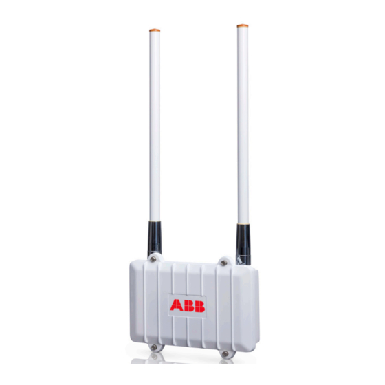
Antenna Information This chapter provides information on the integrated antenna for the Tropos 1410. AN074077 One outdoor 7.4dBi omni Elevation unit-mounted antenna • N connector • 2400-2483 MHz • Length: 19 in (48.3 cm) • Weight: 4.7 oz (.133 kg) •... -
Page 57: Wind Loading Considerations
1 square foot. Pole manufacturers have indicated that small communications devices such as the Tropos 1410 do not present any significant static or dynamic load to these structures. -
Page 58: Abbreviations
Category Complementary Code Keying Conformite Europeene Code of Federal Regulations CISPR International Special Committee on Radio Interference Canadian Standard Association Decibels Decibels Relative to an Isotropic Radiator Decibels Referred to 1 Milliwatt DBPSK Differential-Binary Phase-Shift Keying Tropos 1410 Installation Guide... - Page 59 Instrumentation, Scientific, and Medical band ISTA International Safe Transit Association Local Area Network Mbps Megabits Per Second Megahertz MIL-STD Military Standard MPHPT Ministry of Public Management, Home Affairs, Posts and Telecommunications (Japan) Multiple Service Operator MTBF Mean Time Between Failure Tropos 1410 Installation Guide...
- Page 60 Received Signal Strength Receive Receive Data Technical Inspection Association Transmit Transmit Data Underwriters Laboratories Uninterruptible Power Supply Voltage (Alternating Current) VCCI Voluntary Control Council for Interference (Japan) Voltage (Direct Current) VSWR Voltage Standing Wave Ratio Watts Tropos 1410 Installation Guide...
-
Page 61: Index
FCC antenna rules 13 regulatory notices 2 RJ45 Ethernet ports 28 installation hardware and tools 16 installation, site surveys 17 safety installing Tropos 1410 12 general considerations 17 interfaces 52 information 33 site planning 16 site surveys 17 LAN port 28... - Page 62 27 mounting options 18 tools for installation 16 tower mounting 26 Tropos 1410 diagram 14, 15 exploded view 14, 15 models 13 warnings, general 6 wind loading 57 wood brace mounting 25 wood pole mounting 23 Tropos 1410 Installation Guide...
Need help?
Do you have a question about the Tropos 1410 and is the answer not in the manual?
Questions and answers