Table of Contents
Advertisement
Quick Links
Advertisement
Table of Contents

Subscribe to Our Youtube Channel
Related Manuals for Thermo King 98212


Summary of Contents for Thermo King 98212
- Page 1 Maintenance Manual SB-210+ SB-210+ SB-210+ MAGNUM + Additional text information Additional text information Additional text information to be placed here to be placed here to be placed here TK 60275-4-MM (Rev. 3, 08/15) TK 5XXXX-X-PL TK 5XXXX-X-PL TK 5XXXX-X-PL...
- Page 3 MAGNUM+ TK 60275-4-MM (Rev. 3, 08/15) Copyright © 2012 Ingersoll Rand - EMEIA Printed in Ireland...
- Page 4 Thermo King Corporation should be consulted if further information is required. Sale of product shown in this manual is subject to Thermo King’s terms and conditions. This includes, but not limited to, the Thermo King Limited Express Warranty. Such terms and conditions are available upon request.
- Page 5 Ester compressor oil in tightly sealed containers. If Polyol Ester oil becomes contaminated with moisture or standard oils, dispose of properly–DO NOT USE. When servicing Thermo King R-404A unit, use only those service tools certified for and dedicated to R-404A refrigerant and Polyol Ester compressor oils.
-
Page 6: Table Of Contents
Table of Contents Safety Instructions ............... 9 General Precautions . - Page 7 Table of Contents Software Version 2.4.2.0 120313 ............48 Software Version 2.4.3.0 120628 .
- Page 8 Table of Contents Miscellaneous Settings ..............82 Datalogger Menu .
- Page 9 Table of Contents Controller Maintenance ..............147 Controller Door Open and Close Instructions .
- Page 10 Table of Contents Unit Preparation and Hookup ............182 Unit Evacuation .
-
Page 11: Safety Instructions
Safety Instructions General Precautions • Always wear goggles or safety glasses. Refrigerant liquid and battery acid can permanently damage the eyes. • Never operate the unit with the discharge valve closed. Never close the compressor discharge valve with the unit in operation. •... -
Page 12: Electrical Precautions
Safety Instructions Electrical Precautions The possibility of serious or fatal injury from electrical shock exists when servicing a refrigeration unit. Extreme care must be used when working with a refrigeration unit that is connected to its power source. Extreme care must be used even if the unit is not running. Lethal voltage potentials can exist at the unit power cord, inside the control box, inside any high voltage junction box, at the motors and within the wiring harnesses. -
Page 13: Low Voltage
Safety Instructions Low Voltage Control circuits are low voltage (24 Vac and 12 Vdc). This voltage potential is not considered dangerous. Large amount of current available (over 30 amperes) can cause severe burns if shorted to ground. Do not wear jewelry, watch or rings. These items can shortcut electrical circuits and cause severe burns to the wearer. -
Page 14: Welding Of Units Or Containers
Safety Instructions Welding of Units or Containers Electric welding can cause serious damage to electronic circuits when performed on any portion of the refrigeration unit, container or container chassis with the refrigeration unit attached. It is necessary to ensure that welding currents are not allowed to flow through the electronic circuits of the unit. The following statements must be rigidly adhered to when servicing these units to avoid damage or destruction. - Page 15 Safety Instructions AXA0214 AXA0215 AXA0216 AXA0217 BEN074 AXA0218 Controller Nameplate Unit Nameplate Compressor Nameplate Nameplate and Warning Locations...
-
Page 16: Identifying Unit Safety And Warning Decals
Safety Instructions Identifying Unit Safety and Warning Decals Serial number decals, refrigerant type decals and warning decals appear on all Thermo King ® equipment. These decals provide information that may be needed to service or repair the unit. Service technicians should read and follow the instructions on all warning decals. -
Page 17: Service Guide
Service Guide Service Guide A closely followed maintenance program will help to keep your Thermo King unit in top operating condition. The following service guide table should be used as a guide when inspecting or servicing components on this unit. -
Page 18: Specifications
Specifications System Net Cooling Capacity— Full Cool MAGNUM+ Model — Air Cooled Condensing* 460/230V, 3 Phase, 60 Hz Power Net Cooling Capacity Power Return air to Consump evaporator coil 60 Hz 60 Hz 60 Hz Power inlet Capacity Capacity B/hr 21.1 C (70 F) 56,700 16.603... -
Page 19: Electrical System Specifications
Specifications Electrical System Specifications Compressor Motor: Type 460/380V, 60/50 Hz, 3 Phase Kilowatts 4.48 kW @ 460V, 60 Hz Horsepower 6.0 hp @ 460V, 60 Hz 3550 RPM @ 460V, 60 Hz Locked Rotor Amps 70 amps @ 460V, 60 Hz Condenser Fan Motor: Type 460/380V, 60/50 Hz, 3 Phase... -
Page 20: Refrigeration System Specifications
Specifications Refrigeration System Specifications Compressor: Model No.: ZMD18KVE-TFD-277, Scroll Refrigerant Charge: MAGNUM+ 4.0 Kg (8.0 lb.) R-404A Compressor Oil Capacity 1.77 liter (60 oz.)* Compressor Oil Type: Polyol Ester Based Type (required), (refer to Tool Catalog)** *When the compressor is removed from the unit, oil level should be noted or the oil removed from the compressor should be measured so that the same amount of oil can be maintained in the replacement compressor. - Page 21 **Discharge pressure is determined by condenser fan cycling. MP-4000 Controller Specifications Temperature Controller: MP-4000 is a controller module for the Thermo King Magnum+ Unit. Additional requirements can be met by means of expansion modules. The MP4000 is solely responsible for temperature...
- Page 22 Specifications MP-4000 Controller Specifications (Continued) Demand defrost function initiates defrost when: • Temperature difference between the return air sensor and Demand Defrost defrost (evaporator coil) sensor is too large for 90 minutes • Temperature difference between the supply air sensors and return air sensor is too large Defrost Timer: Evaporator Coil Temperature must be below 5C (41 F) to activate...
- Page 23 Specifications Physical Specifications (Continued) Weight (net): MAGNUM+ Base Unit 380 Kg (875 lb.) Water-cooled Condenser-Receiver Option 13.6 Kg (30 lb.) AMA313 Unit Dimensions: A = Flange Width 2025.5 mm (79.74 in.) B = Gasket Width 1935 mm (76.18 in.) C = Unit Width 1894 mm (74.57 in.) D = Flange Height 2235.2 mm (88.00 in.)
-
Page 24: Unit Description, Features & Options
Unit Description, Features & Options Introduction This chapter will briefly describe the following items: • General Unit Description. • Standard Component Descriptions. • Optional Component Descriptions. General Description MAGNUM units are all-electric, single-piece, refrigeration units with bottom air supply. The unit is designed to cool and heat containers for shipboard or overland transit. -
Page 25: Scroll Compressor
Unit Description, Features & Options • Fresh Air Exchange System • Receiver Tank Sight Glass • Evaporator Fans • Condenser Fan Control • Suction/Discharge Pressure Sensor (Optional) • Remote Monitoring Receptacle Option (4-pin) (optional) • Remote Monitoring Modem (RMM, RMM+) (Optional) •... -
Page 26: Mp-4000 Controller
Unit Description, Features & Options MP-4000 Controller The MP-4000 is an advanced microprocessor controller that has been specially developed for the control and monitoring of refrigeration units. See “Controller Description and Operating Chapter” for more detailed information. BEN074 MP-4000 Controller Figure 4: MP-4000 Controller Power Module Fuses The PM-4000 Power Module in the MAGNUM Plus unit uses Ultra Fast 20 amp fuses to protect the... -
Page 27: Compressor Digital Control Valve
Unit Description, Features & Options Compressor Digital Control Valve The MP-4000 controller pulses the Compressor Digital Control solenoid valve between open and closed positions. This provides precise cooling capacity control. No pump down function or warm gas bypass control is used in conjunction with the Compressor Digital Control valve. See the “General Theory of Operation Chapter”... -
Page 28: Fresh Air Exchange System
Unit Description, Features & Options Fresh Air Exchange System The fresh air exchange system removes harmful gases from containers carrying sensitive perishable commodities. The fresh air vent is located above the control box. The fresh air vent is adjustable to accommodate a variety of frozen and chilled load operating conditions. -
Page 29: Condenser Fan Control
Unit Description, Features & Options The evaporator fan low speed RPM is one-half the high speed RPM. The controller determines evaporator fan motor speed based on the setpoint temperature and the Economy mode setting. NOTE: If Non-Optimized mode is on: •... -
Page 30: Unit Options
Unit Description, Features & Options Unit Options This unit is available with several options that are listed in Figure 11. These options are specified when placing the order. These options are briefly described on the following pages. BEN061 Electronic Chart Recorder (Optional) AVL, AFAM, AFAM+ Options USDA Sensor Receptacle (Access from Inside Container) (Optional) -
Page 31: Electronic Chart Recorder (Optional)
Unit Description, Features & Options Electronic Chart Recorder (Optional) The electronic chart recorder will take the datalogger data from the controller and print the return air sensor values. Remote Monitoring Modem (RMM, RMM+) (Optional) A REFCON remote monitoring modem is provided to permit remote monitoring via the power cable. High speed transmission reads all controller information. -
Page 32: Air Ventilation Logging (Avl - Optional)
Unit Description, Features & Options Air Ventilation Logging (AVL - Optional) AVL is used for detecting and logging the fresh air exchange position on the manual fresh air vent. The opening angle of the fresh air vent is converted to an output signal from approximately 2-5 volts. The disk opening is detected in steps of 0-125, 150, 175, 215 and 225 m /hr. -
Page 33: Advanced Fresh Air Management Plus (Afam+) System (Optional)
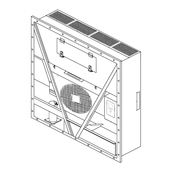
Unit Description, Features & Options AFAM Vent Door Assembly A microprocessor controlled vent door provides programmable control of the air exchange rate. The vent door is adjusted to the desired position by a vent door motor and linkage assembly, shown in Figure 14. The system is pre-calibrated for air exchange rates of 0 to 225 m /hr. - Page 34 Unit Description, Features & Options Evaporator Access Door Condenser Fan Compressor Compartment Scroll Compressor Control Box Rear Download and USDA Receptacle Panel (Access from Inside Container) Figure 15: Unit Front View...
- Page 35 Unit Description, Features & Options AXA0238 Evaporator Grille Air Channels Fresh Air Inlet Top Rear Plate Bottom Rear Plate USDA Receptacle Panel: • Controller Communications and Data Download Port • USDA1/Spare 1 Sensor Connection • USDA2/Spare 2 Sensor Connection • USDA3/Spare 3 Sensor Connection •...
- Page 36 Unit Description, Features & Options Expansion Valve Ball Valve Evaporator Coil Digital Control Valve Expansion Valve (Economizer) Low Pressure Cutout Switch Condenser Coil 10. Economizer Heat Exchanger Receiver Tank Vapor Injection Solenoid Valve Scroll Compressor 12. Dehydrator Figure 17: Refrigeration System...
- Page 37 Unit Description, Features & Options Sensor Kit 15. Humidity Sensor Evaporator Fans Harness 16. Vapor Injection Valve Power Cable Bracket 17. Compressor Sensor Power Cable 18. Digital Valve Power Plug 19. Control Box Scroll Compressor 20. Compressor Cable HPCO Switch 21.
- Page 38 Unit Description, Features & Options Metric Hardware Torque Charts Bolt Size Bolt Type and Class* N.m (Ft.-lb.) N.m (Ft.-lb.) N.m (Ft.-lb.) N.m (Ft.-lb.) HH – CL 5.8 6-9 (4-7) 12-16 (9-12) 27-34 (20-25) 48-61 (35-40) HH – CL 8.8 10-13 (7-10) 20-27 (15-20) 41-47 (30-35) 75-88 (55-65)
-
Page 39: Controller Description
Controller Description Controller Description The MP-4000 is an advanced microprocessor controller. It has been specially developed for the control and monitoring of refrigeration units. The controller contains the following basic features: •Temperature area. Displays Return air sensor, Supply air sensor, Temperature/Message Status Display: and Setpoint •... - Page 40 Controller Description • Evaporator fan motor operation • Compressor digital valve • Vapor injection valve • Dehumidify valve • Electric heaters • Phase selection Standard Display Function Keys Special Function Keys Figure 19: MP-4000 Controller Display Panel BEN040...
-
Page 41: Standard Display
Controller Description Standard Display The Standard Display is a ¼ VGA graphical type display. The temperature can be displayed in Celsius or Fahrenheit. The standard display will display the controlling sensor and Setpoint. The Setpoint will be the low reading with the C or F. Once a key is pressed the Standard display will change to the Unit Status Display. - Page 42 Controller Description Unit Status Display Figure 21: Unit Status Display The Unit Status display will show. Looking at the display from top to bottom • Date and Time / Alarm Warning • rH Relative Humidity sensor • AVL Door Position/AFAM+ •...
-
Page 43: Glossary Of Mode Descriptions
Controller Description Glossary of Symbols (Continued) - Compressor On Unloaded - Compressor On loaded without Vapour Injection - Compressor On loaded with Vapour Injection - SmartPTI has recently been running and no problems found - Controlling mode optimized - Controlling mode economy - Bluetooth - Cell Phone - GPS Signal... -
Page 44: Function Keys
Controller Description Chilled/Heating Chilled heating is a mode the Unit setpoint is set to above -10C. The function here is to maintain setpoint temperature by controlling the temperature on the supply air. The supply air is not allowed to be lower than the setpoint. Chilled heating mode can operate the unit where only the evaporator fan low speed is running, evaporator high speed is running or evaporator high speed and heat is on. -
Page 45: Three Special Function Keys
Controller Description Indicator LEDs Two status indicator LEDs are located just under the F1-F4 function keys Green Led Flashing Temperature approaching in-range Solid emperature In-Range Red Led Flashing Alarm present and has not been acknowledged Solid Alarm present and has been acknowledged Three Special Function Keys The Special Function keys are located around the TK Logo. -
Page 46: Mp-4000 Software
Controller Description MP-4000 Software The various software versions are listed below. Software Version 2.3.4 100927 Release Date New Features September 2010 Unit Running No Display If PTI key is pressed before unit is up and running, unit could run with no display. Added time delay to key function. -
Page 47: Software Version 2.3.6 110301
Controller Description Software Version 2.3.6 110301 Release Date New Features April 2011 Cold Treatment Feature Cold Treatment (CT) has been added for all prefixes except OOLU. Multi Temperature Settings Multi Temperature settings has been add for all prefixes (including OOLU). Chilled PTI Chilled PTI test only has been added as a selection under the COMMANDS menu. -
Page 48: Software Version 2.3.7.0 110608
Controller Description Software Version 2.3.7.0 110608 Release Date New Features June 10, 2011 MTS and CT Feature Selectable MTS and CT must be selected through the CONFIGURATION/OPTIONS menu, “MTS FEATURE ON/OFF” oCT FEATURE ON/OFF”. CT is not allowed with OOCL prefix. MTS Feature Selects Present Set Point MTS feature will now select the present set point as first set point and not the last MTS set point. -
Page 49: Software Version 2.3.8.0 110628
Controller Description Software Version 2.3.8.0 110628 Release Date New Features June 29, 2011 Padlock Option The Keypad Lock feature has been added for all customers. In PADLOCK state no user intervention is allowed. Option is found in CONFIGURATION/UNIT SETTING/PADLOCK OPTION. Default is OFF. Select PADLOCK OPTION and select ON, press hold the F4 key to lock. -
Page 50: Software Version 2.4.0.0 111220
Controller Description Software Version 2.4.0.0 111220 Release Date New Features January 2012 MP4000 Test System Tool Introduce field tester system tool (8232-010) functionality. Alarm 127 GENERAL UNIT ERROR Introduced Alarm 127 GENERAL UNIT ERROR shut down alarm. If controller is missing needed information to run alarm will be set and unit will shut down. -
Page 51: Software Version 2.4.3.0 120628
Controller Description Software Version 2.4.3.0 120628 Release Date New Features June 2012 RMM Built in Option Added prefixes FOR RMM option TEMU915380 through 915579 GCNU880256 through 880455 CGNU800050 through 800099 Optimize (OPT) Icons indicating controlling mode OPT have been added to the state/Icon line of the standard display. -
Page 52: Software Version 2.5.0.0 121121
Controller Description Software Version 2.5.0.0 121121 Release Date New Features November 2012 RMM Built in Option Added prefixes FOR RMM option. TEMU908680 through 909879 TEMU917080 through 917379 Display Contrast Improvement Have improved temperature compensation on adjusting display contrast. Gas Sensor ON/OFF Handling Change to help extend sensor life. -
Page 53: Software Version 2.5.1.0 130213
Controller Description Software Version 2.5.1.0 130213 Release Date New Features February 2013 Alarm 137 Sensor System Overload Introduced Alarm 137 Sensor System Overload. If a short occurs on one of the analog inputs, humidity sensor, compressor sensor, transducers, it causes an overload to the converter circuit and the controller will display invalid readings. -
Page 54: Software Version 3.1.0.0 140612
Controller Description Software Version 3.1.0.0 140612 Release Date New Features June 2014 Software File Format SIP In version 3.0.0.0 we introduced the SIP file format for adding options like RMM to the unit. Version 3.1.0.0 120612 is released in this SIP format. CM4000_3.1.0.0.120612.srip.sip In order to load version 3.1.0.0 software the MP4000 controller needs to have 3.0.0.0 software installed first. -
Page 55: Software Version 3.2.0.0 140822
Controller Description Software Version 3.2.0.0 140822 Release Date New Features August 2014 RMM Option Container prefixes have been added for the RMM option. SUDU118000 – 118999, SUDU806000 – 807699, SUDU808000 – 808799 SMART PTI Option Container prefixes have been added for the SMART PTI option. BCHU140X, BCHU150X, BCHU240X, BCHU250X, DCHU251X, BCHU267X, BCHU596X Humidity Sensor Alarm 60 Criteria for humidity sensor surveillance have been improved. -
Page 56: Operating Instructions
Operating Instructions Function Keys ON/OFF Key Defrost Key PTI - Pre-trip Inspection F1. Alarm Key F2. C/F Key F3. Setpoint Key F4. Menu Key Figure 24: Function Keys... -
Page 57: Unit On/Off Key
Operating Instructions Unit On/Off Key •ON. Unit will operate on Cool or Heat depending on the controller setpoint temperature and the container air temperature. •OFF. The unit will not operate. Sequence Of Operation Unit Start-up Connect unit to 460 Volt shore power or genset. Turn circuit breaker on at post to apply power to unit. -
Page 58: Pti
Operating Instructions Turn the U . Allow Unit to start and stabilize. Complete the following steps: 1.Press the PTI Special Function key. 2. Press the F2/F3 keys to scroll down to select from the different PTI test. 3. Press the F4 key to ACCEPT and start the PTI or test. During testing the screen is divided into 3 sections. -
Page 59: Viewing Alarms/Warnings
Operating Instructions NOTE: Detailed PTI test results are stored in the MP-4000 Datalogger for later viewing. Any alarm codes recorded during the test can be viewed through the controller’s Alarm List menu at the end of the test. Viewing Alarms/Warnings To view the alarms that are present, turn the U .Allow Unit to start and stabilize. -
Page 60: Controller Back-Up Battery
Operating Instructions Lock Padlock If PADLOCK is active technician must enter correct key (number) to unlock display. PADLOCK OPTION must be selected ON under the CONFIGURATION/UNIT SETTING for it to be active or visible. Figure 25: Lock Padlock Controller Back-up Battery Every Controller has a Back-up Battery. -
Page 61: Emergency Run Mode
Operating Instructions In order to load version 3.1.0.0 or later software the MP4000 controller needs to have 3.0.0.0 software installed first. Load to SD Card file contains both 3.0.0.0 and 3.1.0.0 or later software. Figure 26: Load Software to SD Card If controller has 3.0.0.0 software installed, insert SD card to load 3.1.0.0 or later software. - Page 62 Operating Instructions 4. Located J1 connector top left side of PM, disconnect J1 connector from PM. See Figure 28 on page J1 Connector Disconnect from PM CP Wires Connected to Output Side of Main CB CF Wires Connected at J11 and Input Side of Compressor Contactor Figure 28: Rotation Check 5.
-
Page 63: Full Cool Mode
Operating Instructions FULL COOL Mode 1. Unplug unit and turn off the CB located in the controller box. 2. Remove the Condenser Motor wires CF1, CF2, and CF3 from the input side of the compressor contactor, installed during the Rotation Check. Re-tighten input wires. 3. -
Page 64: Defrost Mode
Operating Instructions DEFROST Mode 1. Unplug unit and turn main CB OFF located in the control box. 2. Locate J1 connector disconnected in the FULL Cool mode. Disconnect the jumper wire from pin 1 to pin 6. Black Heater Wire Connected to Compressor Contactor Input Side J1 Connector with Pin 1 Wire Disconnected Figure 30: FULL COOL Mode 3. - Page 65 Operating Instructions EF Wire Connected to Input Side of Compressor Contactor J1 Connector Disconnected from PM Figure 31: High or Low Speed Evap Fans Only Mode...
-
Page 66: Navigating The Controller Operating Menu
Navigating the Controller Operating Menu Navigating the Controller Operating Menu Early Main Menu Display Later Classic Main Menu Display Message Display Menu Scrolling Keys Figure 32: MP-4000 Controller Display Panel... -
Page 67: Icon Menu
Navigating the Controller Operating Menu Icon Menu The later Classic Menu can be changed to an Icon Menu as follows: 1. Press the F4 to display the Classic Menu. ENTER KEY Figure 33: Classic Menu 2. Press the F2 F3 U key to scroll to the Configuration selection and press the F4 ENTER . -
Page 68: Menu Scrolling Keys
Navigating the Controller Operating Menu 2. Press the F2 F3 U key to scroll to the Config selection. Figure 36: Select Configuration 3. Press the F4 . The Configuration Menu will appear. ENTER KEY 4. Press the F2 F3 U key to scroll to the Classic Menu selection. -
Page 69: Changing Screen Contrast
Navigating the Controller Operating Menu • Setpoint/Control Menu – Menu screens in this group are used to enter allowable setpoints. Setpoint menu include: set Cold treatment (CT), Multiple Temp Set (MTS), Optiset, Temperature Setpoint, Controlling Mode, Watercool, Humidity Control, Humidity Setpoint, AVL Open Value, Defrost Terminate Temp (USDA), Defrost Interval (USDA), Special 24-48H Defrost, USDA Trip, AFAM Mode, AFAM Delay, AFAM Rate, CO2 Max, and O2 Min. -
Page 70: Main Menu
Main Menu Main Menu From the Standard Display, press the MENU F4 key to enter the Main Menu as shown below. The Main Menu allows access to several other submenus using the UP F3, DOWN F3, and ENTER F4 keys. The other submenus are described below. -
Page 71: Setpoint/Control Menu
Main Menu Figure 40: Data/Values Menu Setpoint/Control Menu NOTE: When a submenu is highlighted, pressing the ENTER F4 key again will open a view show how the unit is currently set up. In order to see some of these different selections you need to turn the option on and then enter the Setpoint/Control Menu again. -
Page 72: Cold Treatment (Ct)
Main Menu Cold Treatment (CT) This feature is designed to maintain a temperature below the actual set point for a period of time, (per USDA specifications) and then increase the temperature to the final set point. For a complete description see CT “Cold Treatment (CT)”... -
Page 73: Optiset
Main Menu OPTISET Allows all the AFAM variable to be set by selecting a specify commodity. Refer to “Changing the AFAM+ Settings Using ‘OPTISET’” on page 121 and AFAM+ Setting Guide TK51318. AFAM must be selected under the CONFIGURATION/OPTIONS/AFAM MODULE for OPTISET to be active or visible Figure 45: Optiset Display Temperature Setpoint Used to change the controller setpoint. -
Page 74: Controlling Mode
Main Menu Controlling Mode To change the temperature and fan control of the unit. Select from OPTIMIZED or NON-OPTIMIZED. Optimized: The default Mode for the new Magnum+ for temperature and fan control. Non-Optimized: The default Mode for the original Magnum for temperature and fan control. NOTE: Enter setpoint temperature before turning on the Non-Optimized mode. -
Page 75: Watercool
Main Menu Watercool Watercool is turned ON when the unit is equipped with the optional water cooled condenser. When Watercool is turned OFF the condenser fan runs as required. When Watercool is turned ON the condenser fan does not run unless no cooling water is available, then the unit will trip off on HPCO and the condenser fan will run as required. -
Page 76: Humidity Setpoint
Main Menu Humidity Setpoint The relative humidity setpoint can be set from 50 to99 percent. HUMIDITY SENSOR mounted must be selected under the CONFIGURATION/OPTIONS/HUMIDITY SENSOR for HUMIDITY SETPOINT to be active or visible. See complete description of HUMIDITY CONTROL under Operating Theory section of his manual. Figure 51: Humidity Setpoint AVL (Air Ventilation Logging) The Fresh Air Exchange Recorder (AVL) detects vent disk movement and automatically displays a value... -
Page 77: Fresh Air Vent Man - Afam Mode
Main Menu Fresh Air Vent Man - AFAM Mode Can be set to OFF or AFAM. OFF - Will override all settings and keep the AFAM door completely closed. AFAM – Will allow and air exchange Rate and or Delay to be set. See “Starting the AFAM System”... -
Page 78: Afam Delay
Main Menu AFAM Delay Hours the AFAM door will remain closed before opening to a desired AFAM Rate or due to gas sensor readings. This is selectable form 1 to 48 hours. Active in AFAM and AFAM+ modes. Figure 55: AFAM Delay AFAM Rate Use to set AFAM door opens to desired rate, Selectable from 0 CMH to 225 CMH. -
Page 79: Afam+ Co2 Max
Main Menu AFAM+ CO2 Max Used to set the highest level of Carbon Dioxide allowed in the container. The AFAM+ door will open or close to maintain this level. Active only when AFAM+ is enabled. Selectable from 0% to 25%. See “Advanced Fresh Air Management Plus (AFAM+) System”... -
Page 80: Smart Pti
Main Menu Smart PTI Use to enable ON or Disable OFF the Smart PTI surveillance. Smart PTI automatically monitors individual component performance during normal reefer operation and during defrost cycles. When a Smart PTI cycle is completed, the results are stored in the controller memory and a <SMART-PTI Pass> flag is logged. -
Page 81: Warning List
Main Menu Warning List Display show either NO MESSAGES or the newest MESSAGE. See to “Alarms/Warnings Menu” on page 99 for more information. Figure 61: No Warnings or Newest Warning Configuration Menu The Configuration menu is used to select unit configuration settings. A complete listing of the controller Configuration menu is located on an 11”... -
Page 82: Unit Setting
Main Menu Unit Setting Figure 63: Unit Setting Figure 64: Unit Configuration View Container ID : Use to EDIT container ID stored in controller: Select range between 0C and 5C In Range Temperature Limit: Select ON/OFF Padlock Option : Unit Configuration (Configuration Depends on Unit) Figure 65: Unit Configuration Select ON/OFF 20 FT. -
Page 83: Options
Main Menu Options Figure 66: Options This Menu is used to: 1. Turn ON/OFF a Module/Feature. 2. Select a particular Option within a module. 3. Tell the Controller when a Sensor is mounted. Here is the list of Modules, Features and Options under this menu (See Setpoint/Controlling section previously in this chapter for more details on each option): Select from None, AVL, AFAM, and AFAM+. -
Page 84: Miscellaneous Settings
Main Menu Miscellaneous Settings Figure 67: Miscellaneous Settings Displays Current Date and Time - you can also edit. DATE/TIME . To adjust Screen Display contrast. Contrast . Displays Controller Software/Application Revision, Bootloader Revision, Power Firmware Version. Module Revision, Serial Number, and Option File Revision. View and Edit Controller ID. -
Page 85: States Menu
Main Menu States Menu This menu gives an overview of all the tests that are running and also Information on any Special features selected. Figure 69: States Menu Cold Treatment (CT) State: Multiple Temperature Setpoint (MTS) State : PTI: Input - Output: RMM: RMM+ : Defrost:... -
Page 86: Special Function Keys - User Activated Commands
Main Menu Special Function Keys - User Activated Commands Pressing the PTI or DEFROST key will open up for selecting a user activated functionality. Pressing PTI key or DEFROST key alone WILL NOT ACTIVATE THE FUNCTION. PTI Key Figure 70: PTI Menu Screen No Action Manual Function Test See “Manual Function Test”... - Page 87 Main Menu Function Test See “Automated Tests” on page 89 and “Function Test” on page 89 for more information. Figure 72: Function Test Screen AFAM+ PTI Figure 73: AFAM+ PTI Test Screen Humidity Sensor PTI Figure 74: Humidity Sensor PTI Test Screen...
- Page 88 Main Menu Brief PTI See “Automated Tests” on page 89 for more information. Figure 75: Brief PTI Test Screen Chilled PTI Figure 76: Chilled PTI Test Screen See “PTI (Pretrip) Tests” on page 88 for more information. Figure 77: PTI Test Screen...
-
Page 89: Defrost Key
Main Menu Probe Test Figure 78: Probe Test Screen Show PTI Info Figure 79: PTI Information Screen Defrost Key See “Defrost” on page 98 for more information. Figure 80: Defrost Menu Screen... -
Page 90: Pti (Pretrip) Tests
Main Menu Figure 81: Defrost Screen Figure 82: Defrost Information Screen PTI (Pretrip) Tests CAUTION: The PTI tests should only be performed on an empty container! NOTE: Units equipped with a water-cooled condenser must be set to operate on air-cooled condensing to perform a complete system capacity test. -
Page 91: Automated Tests
Main Menu Automated Tests This Screen shows the different states of the PTI, Brief PTI and Function Tests Figure 83: PTI Menu The Screen is divided into three sections: Section 1: Shows the list of test to be performed and there state. List of possible states: 1. -
Page 92: Manual Function Test
Main Menu 3. Press the F4 ENTER K to start the Function Test. Display shows test currently being performed. The Function test ends automatically. Press any key on the controller to return the unit to normal operation. Any alarm codes recorded during the test can be viewed through the controller’s Alarm List menu at the end of the test. - Page 93 Main Menu 4. Repeat step 3 until all required components are on. For example, to operate unit in Full Cool mode, start the following components: • Condenser Fan • Compressor • Capacity 100 percent • Evaporator High or Low 5. Observe current draw and system performance to verify component(s) performance. 6.
- Page 94 Main Menu Display* Description Possible Duration Brief Function Alarms Test (Time) EVAP FAN HIGH 12, 13 5 seconds With evaporator fan on high SPEED TEST speed, amp draw is measured SUP RET EVA and compared to the expected 5.1C 5.0C 5.1C amp draw, in respect to voltage 2.4A 2.3A 2.4A and frequency.
- Page 95 Main Menu Display* Description Possible Duration Brief Function Alarms Test (Time) HEATER TEST Electric heaters are turned on. 10, 11 5 seconds SUP RET EVA Amp draw is measured to the expected amp draw, in respect 1.3C 1.0C 1.3C to voltage and frequency 5.2A 5.1A 5.2A •...
- Page 96 Main Menu Display* Description Possible Duration Brief Function Alarms Test (Time) COMPRESSOR TEST 6, 7 18 seconds Compressor loaded, and con- AMB CON EVA denser fan activated for 10 sec. 8.0C 15.0C 5.0C Followed by compressor run 9.1A 9.0A 9.1A alone for 7 sec before the amp draw is measured and compared to the expected amp draw, in...
- Page 97 Main Menu Display* Description Possible Duration Brief Function Alarms Test (Time) HIGH PRESSURE 53, 54 Max. 200 Running with compressor fully CUTOUT TEST seconds loaded and with evaporator fan at high speed, awaiting high pressure cut out. The test is ended if the condenser coil probe reads temperature above 70ºC and the HPCO does not...
- Page 98 Main Menu Display* Description Possible Duration Brief Function Alarms Test (Time) MAINTAINING 0C TEST None 30 Minutes With the unit running chilled – Non-Optimized, maintaining 0 deg C / 32F. After 30 minutes the probe readings and time are recorded in the pti log.
- Page 99 Main Menu Display* Description Possible Duration Display Alarms (Time) Unit operates in normal mode with 0C (32F) setpoint for 30 minutes after previous test is completed. At the end of RUNNING PTI 30 minutes, “Chill End” temperatures are 0°C / 32°F Supply 120 minutes recorded in PTI log.
-
Page 100: Defrost
Main Menu Defrost With the Unit turned On, Allow Unit to start and stabilize and the Display to show the unit status display (setpoint): 1. Press the D (*) K to open the Defrost Menu. EFROST 2. Press the F2 OR F3 UP/DOWN K to scroll to “Start Defrost”. -
Page 101: Alarms/Warnings Menu
Main Menu Alarms/Warnings Menu There are two types of alerts: Warning indicates corrective action should be taken before a problem becomes severe. When a Warnings: Warning occurs the controller will try to determine if the component or input is good or bad. The Warning description will be displayed across the top of status display and the Red LED will not be turned on. -
Page 102: Alarm/Warning List Menu
Main Menu Alarm/Warning List Menu NOTE: All screens are NOT present on all units. The screens that display on the controller are determined by Controller Software settings and the options installed on the unit. DATA Alarm List/Warning List SETPOINT/CONTROL • View and write down all alarm/warning code. -
Page 103: Warning List Menu
Main Menu NOTE: See detailed Alarm/Warning Code list complete with corrective actions in the Diagnosing and Troubleshooting Section in the back of the manual. Warning List Menu Warning Code Action High Pressure Cut Out, Check Water Cooling High Pressure Cut Out, Check Condenser Probe High Pressure Cut Out, Please Wait Evaporator High Temperature - Check Heater System Low Voltage On Line - Unit Stopped... -
Page 104: Alarm List Menu
Main Menu Alarm List Menu Alarm Code Action Supply Air Sensor Open Circuit Supply Air Sensor Short Circuit Return Air Sensor Open Circuit Return Air Sensor Short Circuit Evaporator Coil Sensor Open Circuit Evaporator Coil Sensor Short Circuit Compressor Current Too High Compressor Current Too Low Heater Current Too High Heater Current Too Low... - Page 105 Main Menu Alarm Code Action Compressor Sensor Short Circuit Digital Valve Error Suction Pressure Sensor Error Discharge Pressure Sensor Error O2 Sensor Calibration Error Datalogger Battery Error Cold Treatment Restart Alarm General Unit Error Supply Air Temperature Probe Error Return Air Temperature Probe Error Evaporator Coil Temperature Probe Error Ambient Condenser Temperature Probe Error Power Module Sensor Error...
-
Page 106: Configuration Menu
Main Menu Configuration Menu The Configuration menu displays a list of functions that identifies unit operating features and current settings. The following functions are available: NOTE: All screens are NOT present on all units. The screens that display on the controller are determined by Controller Software... - Page 107 Main Menu Unit Setting Sets the container identification number. Enter up to 11 characters (numbers or letters). Container ID: Sets the temperature value for the controller’s In-range LED and datalogger In-Range Temperature limit: functions (factory default = 1.5 C [2.7 F]). Enter a value from 0.5 to 5.0 C (0.9 to 8.9 F). Select ON/OFF.
-
Page 108: Set Date And Time
Main Menu c. Press the F4 E and release when the entry is complete. Press the F1 key. The new value NTER KEY appears in the menu line. 5. Repeat steps 3 and 4 to reset additional configuration values. 6. Press the F1 key to exit the Configurations screen. Set Date and Time 1. -
Page 109: Datalogger Menu
Main Menu Datalogger Menu The Datalogger menu contains a list of functions that display unit operating information recorded in the MP-4000 datalogger. The following functions are available: Displays results of last PTI, Event and Temperature test including component volt and amps Inspect Log: data and sensor temperatures. -
Page 110: Inspect Log
Main Menu • [SET LOG TIME INTERVAL] 4. Press F4 E to access the function selected. NTER Inspect Log With the U Allow Unit to start and stabilize and the Display showing the unit status NIT TURNED display (setpoint): 1. Press the F4 M key. -
Page 111: Set Log Time Interval
Main Menu 2. Press the F4 E to expand this menu. NTER KEY 3. Press the F2 F3 U key to scroll through submenu until [TRIP START] appears in display. 4. Press the F4 to enter Trip Start function. The date and time of the last trip start appears in ENTER KEY the screen. -
Page 112: States Menu
Main Menu States Menu NOTE: All screens are NOT present on all units. The screens that display on the controller are determined by Controller Software settings and the options installed on the unit. DATA - Cold Treatment (CT) State - Multiple Temperature Setpoint (MTS) State SETPOINT/CONTROL - PTI - INPUT-OUTPUT... - Page 113 Main Menu Output Information • Economizer Valve • Digital Valve • Heater • Evaporator Fan High • Evaporator Fan Low • Condenser Fan • Compressor RMM and RMM+ States The RMM (Remote Monitoring Modem) State and RMM+ State menus display the current communications status with a REFCON system: No communication between the controller RMM and a REFCON system.
-
Page 114: Air Ventilation Logging (Avl)
Main Menu Defrost Shows the following: Compressor Defrost Timer [hours] Timer Defrost timer Limit [hours] Water Cooled Condenser Shows information on the Water Cooled Condenser State if used. Runtime Counters Shows information on the Runtime Counters for the compressor, heating elements, evaporator fan. condenser fan, and main power. - Page 115 Main Menu 6. Press the F2 F3 key until it highlights AVL. Press and hold the F4 key until the display returns to the AFAM Module/Controlled Atmosphere (CA) selection. The unit is now configured to log the vent door motion. 7.
-
Page 116: Starting The Afam System
Main Menu Starting the AFAM System 1. Press the M F4 key to enter the main menu. Press the F2 or F3 key to scroll to Config Menu and press F4 to expand the menu. 2. Press the F2 or F3 key to scroll to Options Menu and press F4 to expand the menu. 3. - Page 117 Main Menu Figure 94: Fresh Air Vent Man Menu 10. Press and hold the F4 key with the desired state in the menu line until you are returned to the Setpoint/Control menu. 11. Press the F1 key several times to return to the standard display. NOTE: All screens are NOT present on all units.
-
Page 118: Change The Afam Delay
Main Menu Change the AFAM Delay NOTE: The fresh air exchange time delay should be established by the shipper. The AFAM delay setting keeps the fresh air vent closed for a preset time when the unit starts. This allows faster product temperature pull-down. The AFAM delay can be set from 1 to 72 hours in 1-hour increments. -
Page 119: Advanced Fresh Air Management Plus (Afam+) System
Main Menu 2. Press the F2 or F3 key to scroll to [AFAM RATE] line. Press F4 to enter menu. The current rate and units (e.g. “0 CFM”) appears in the display. 3. Press the F2 F3 key to increase or decrease the AFAM Rate. Units Rate Setting 0 to 132 Cubic Feet Per Minute... - Page 120 Main Menu 4. Press the F2 or F3 key to select AFAM+ and Press and hold F4 to accept the selection. Figure 97: Controlled Atmosphere (CA) Menu 5. Press the F1 key several times to return to the standard display. 6.
-
Page 121: Change The Afam Delay
Main Menu 10. Press and hold the F4 key with the desired state in the menu line until you are returned to the Setpoint/Control menu. 11. Press the F1 key several times to return to the standard display. Change the AFAM Delay NOTE: The fresh air exchange time delay should be established by the shipper. - Page 122 Main Menu 2. Press the F2 or F3 key to scroll to “CO MAX” line. 3. Press the F4 key to enter the CO MAX menu. The current rate and units (e.g. “2.5 percent”) appears in the display. 4. To change the rate, press the F2 F3 key to increase or decrease the CO2 Max setting.
-
Page 123: Changing The Afam+ Settings Using 'Optiset
Main Menu Changing the AFAM+ Settings Using ‘OPTISET’ 1. Press the M F4 key to enter the main menu. Press the F2 or F3 key to scroll to Setpoint/Control Menu and Press F4 to expand the menu. 2. Press the F2 or F3 key to scroll to Optiset Menu. 3. -
Page 124: Testing Afam+ / Afam System
Main Menu 3. Example. Modifying the O2 and CO2 settings: 4. Press F3 key to scroll to ‘O2 MIN’. 5. Press the F2 F3 key to increase or decrease the O2 Min supplied by the shipper. 6. Press and hold the F4 key until you are returned to the main menu. The new rate is recorded in the datalogger and appears on the Display. - Page 125 Main Menu 1. Enter ‘Configuration’ menu. 2. Use F2 or F3 key to scroll to ‘Auto Config’ menu line. 3. Press F4. The password line appears. 4. Press the following keys in this order: • F2, then A, then F4, then EXIT 5.
- Page 126 Main Menu Data Menu Display Indication Corrective Action(s) CO2% Open or Short If no alarm has been generated, the system most likely has not communicated with or is verifying communications with the analyzer. Follow action for ‘Stale Atmosphere’ steps noted above. If fault exists, an alarm will be generated.
-
Page 127: Pulsating Vent Door
Main Menu Pulsating Vent Door AFAM+ Door Closes Automatically On units equipped with the AFAM option, a harness from J_B12 to the on/off switch, and a container prefix of HLXU. If the AFAM door is open it will close automatically if the on/off switch is turned off. Unit and controller will shut off and the AFAM door will be power close. -
Page 128: Operating Theory
Operating Theory Chill Loads: (Setpoint at -9.9 C [14.1 F] and Above) The unit operates on Cool with Modulation and Heat to provide accurate control of chill loads. During Cool with Modulation, the controller uses a proportional-integral derivative (PID) algorithm, and a Digital Control valve to provide accurate control of the container temperature in direct response to load demand. -
Page 129: High Temperature Protection
Operating Theory • Chill or Power Limit Mode: When the cool capacity is 100 percent (in the display), the controller energizes the vapor injection valve continuously. • Compressor discharge temperature exceeds 138 C (280 F). Vapor injection stops when the compressor discharge temperature decreases 6 C (10.7 F). -
Page 130: Probe Test
Operating Theory Probe Test The controller constantly monitors t supply sensor, return sensor and evaporator coil sensor to determine when to initiate a demand defrost. If a demand defrost is requested and defrost has occurred within last 90 minutes, the controller initiates a probe test to check for a defective sensor. During a Probe test, the Display shows “PROBE TEST PLEASE WAIT”. - Page 131 Operating Theory AXA0156 Cool with Modulation (control temperature differential is above setpoint) Heat (electric heaters pulse on and off on a 60 second duty cycle if the control temperature differential is below setpoint.) In-range (based on supply air temperature) Decreasing Temperature Setpoint Increasing Temperature Chill Load Control Sequence (Setpoints at -9.9 C [14.1 F] and Above)
- Page 132 Operating Theory MAGNUM+ Operating Mode Function Chart Chill Loads Frozen Loads Setpoints at -9.9 C Setpoints at -10 C (14.4 F) and Above (14 F) and Below Cool w/Mod Heat Defrost Cool Null Defrost Unit Function • • Evaporator Fans High Speed •...
-
Page 133: Frozen Loads (Controller Setpoint At -10 C [14 F] And Below)
Operating Theory Cool with Modulation • Controller calls for the Cool mode whenever the Control Temperature Differential (based on supply air temperature) is above setpoint. • Controller turns on the Compressor indicates when the compressor is operating. • Controller opens and closes Digital Control valve to control the compressor load. The duty cycle of the Digital Control valve balances the unit cooling capacity against the actual load requirements. - Page 134 Operating Theory Cool In-range Null Decreasing Temperature Setpoint Increasing Temperature Figure 103: Frozen Load Control Sequence (Setpoints at -10 C [14 F] and Below) Cool • After initial start-up and pull-down to 2.0 C (3.6 F) below setpoint, the controller calls for the Cool mode whenever: •...
- Page 135 Operating Theory Defrost The evaporator coil sensor temperature must be below 18 C (65 F) to initiate a Demand Defrost or Manual Defrost. The evaporator coil sensor temperature must be below 4 C (39 F) to initiate a Timed Defrost. •...
-
Page 136: Compressor Digital Control Valve
Operating Theory When the defrost mode is terminated: • The Heat and Defrost indicators turn off and the solid state is de-energized. The controller starts the compressor to pre-cool the evaporator coil. The condenser fan starts if required. The controller pre-cools the evaporator coil to the supply air temperature (or for 3 minutes maximum) to minimize heat energy release into the container. -
Page 137: Economizer System
Operating Theory Economizer System An economizer heat exchange system replaces the conventional heat exchanger. The economizer system subcools the liquid refrigerant before it reaches the evaporator expansion valve. Subcooling liquid refrigerant increases the cooling efficiency and capacity of the evaporator. AXA0427 Figure 105: Economizer Heat Exchanger A vapor injection line tee is located in the liquid line between the filter drier/in-line filter and the... -
Page 138: Cold Treatment (Ct)
Operating Theory Trip data can be retrieved (but not erased) from the data-logger memory using a LOGMAN II handheld data retriever, LOGMAN II PC used on a laptop PC or a REFCON power line remote monitoring system. LOGMAN II data transfer rate based on a 1 hour log interval is about 15 seconds per month of event logs and about 70 seconds per month of temperature logs. - Page 139 Operating Theory Commodity is loaded Final set point Commodity reached Pre-cool is unloaded Pulling down USDA MAX temperature Maintaining final set point Warm up C/T Period Maintaining C/T Set point C/T period C/T Period started Passed Figure 107: Details of CT Log Trip Action and Unit Mode •...
- Page 140 Operating Theory Unit Requirements To activate CT the unit must have: • 1-3 UDSA or Cargo sensors • Battery (Battery is required for off power logging). Activating Cold Treatment • Go to the Configuration > Options Menu enter CT Feature and turn it ON. Figure 108: Turn CT Feature On Calibrate Probe (Optional) Setting the USDA Type in the Configuration menu activates spare sensors 1, 2, 3 and 4 for USDA Cold...
- Page 141 Operating Theory NOTE: The sensors must be completely immersed in the ice bath without contacting the walls of ice bath container for 5 minutes. 2. Press the F4 M key. Press the F3 key to scroll down to the CONFIGURATION Menu. NOTE: All screens are NOT present on all units.
- Page 142 Operating Theory Figure 111: Calibrate Probes The controller displays [COOR] in place of a temperature offset until the sensor comes within 0.3 C (0.5 F) above or below 0 C (32 F). The controller displays the actual temperature offset when the sensor temperature is within 0.3 C (0.5 F) above or below 0 C (32 F).
- Page 143 Operating Theory Figure 113: Standard Display Showing CT In Process Stopping Cold Treatment 1. Press the CT Key. 2. Scroll down to ABORT CT - PRESS >STOP< and press STOP. Figure 114: Stopping CT 3. The Standard Display will appear and “CT In Progress” will disappear from the display. Passed Cold Treatment –...
-
Page 144: Multiple Temperature Setpoint (Mts)
Operating Theory Associated tools LogView must be updated to Version 5.8.2.0 to report the cold treatment events Various actions: When the user activates the cold treatment, a trips start mark and event is automatically made. Multiple Temperature Setpoint (MTS) To be able of transporting a commodity under the best possible temperature scheme, the MP4000 is capable of controlling the temperature through a set of temperatures. - Page 145 Operating Theory Activating Multiple Temperature Setpoint • Go to the Configuration > Options Menu enter MTS Feature and turn it ON. Figure 116: Turn MTS Feature On Starting and Setting Multiple Temperature Setpoint 1. Go to the Setpoint/Control and enter Multiple Temp Set (MTS). 2.
- Page 146 Operating Theory 3. Select MTS Temperature Setpoint 1 and press EDIT. The following screen will appear. Press UP and/or DOWN to change the setpoint to the desired setting and Press and hold ACCEPT to enter that setpoint. Figure 118: Setting MTS Temperature Setpoint 1 4.
- Page 147 Operating Theory 6. Select EXIT. The Standard Display will appear showing “MTS - Approaching setting 1” indicating MTS is active. Figure 121: Standard Display Showing MTS In Process Stopping Multiple Temperature Setpoint 1. Press the MTS Key. 2. Scroll down to ABORT MTS - PRESS >STOP< and press STOP. Figure 122: Stopping MTS 3.
- Page 148 Operating Theory Changing Multiple Temperature Setpoint Settings 1. Press the MTS Key. 2. Scroll up and down to select and edit the setting to be changed. Select EXIT to return to Standard Display and continue MTS with the new setting. Figure 123: Changing MTS Settings Surveillance during the multi temperature setting trip During the treatment the normal unit surveillance is kept.
-
Page 149: Controller Maintenance
Controller Maintenance Controller Door Open and Close Instructions Open 1. Insert a flat blade screwdriver into slot on side of control box door. 2. Move the screwdriver handle to the left to release the door catch from the box latch. 3. -
Page 150: Flash Loading Controller Software
Controller Maintenance 2. With hand, rap the door to confirm it is closed properly. Flash Loading Controller Software Controller software must be flash loaded when software has been revised. Flash load software complete as follows: Download the latest software file from Global Marine Solution Info Central site/Software Update/MP4000. - Page 151 Controller Maintenance Figure 124 Removable Disk (E:) / MP4000 /command.ini 3/18/2010 Figure 124: MP4000 Figure 125 Removable Disk (E:) / MP4000 / Firmware CM4000_3.2.0.0_140822.strip / Logs Downloads will appear here /command.ini 3/18/2010 Figure 125: MP4000/Firmware...
- Page 152 Controller Maintenance Software File Format SIP In version 3.0.0.0 we introduced the SIP file format for adding options like RMM to the unit. Version 3.1.0.0 120612 and later were released in this SIP format. CM4000_3.1.0.0.120612.srip.sip In order to load version 3.1.0.0 or later software the MP4000 controller needs to have 3.0.0.0 software installed first.
-
Page 153: Mp-4000 Test System Tool
Controller Maintenance MP-4000 Test System Tool The MP-4000 Test System Tool has the ability to test the following components: • Controller Module (CM) • Power Module (PM) • Interconnect Cable • Keypad • Displays IMPORTANT: As of February 1st, 2012, no failed Controller Module (CM) or Power Module (PM) will be accepted under Warranty without a ‘Failed Component’... -
Page 154: Controller Replacement
Controller Maintenance Controller Module Test Plugs Analog 2 #J1 1934-001 Analog 3 #J3 1934-002 Analog 1 #J4 1934-003 Digital 1 #J9 1934-004 Com 2=3 J28=J2 1934-005 Power Module Test Plugs PM test Adaptor #J1 1934-007 Expansion Module Test Module 1934-006 Controller Replacement 1. -
Page 155: Electrical Maintenance
Electrical Maintenance Unit Protection Devices Introduction The unit has numerous protection devices. They are described in detail on the following pages. Main Circuit Breaker The main power circuit breaker is located in the control box. The 25 ampere manual reset circuit breaker is located in the Control Box. - Page 156 Electrical Maintenance Low Pressure Cutout Switch High Pressure Cutout Switch Figure 128: Low and High Pressure Cutout Switches • The controller continues to call for cooling so the compressor will restart when the overload condition is corrected (switch resets) if power is available. •...
-
Page 157: High Pressure Cutout Manifold
Electrical Maintenance High Pressure Cutout Manifold 1. Connect the manifold gauge to the compressor discharge service valve with a heavy duty, black jacketed thick wall #HCA 144 hose with 6024 kPa, 60.24 bar, 900 psig working pressure rating. 2. Operate the unit in Cool by performing a Capacity 100 percent test from the Manual Function Test menu of the controller. -
Page 158: High Pressure Cutout Switch Installation
Electrical Maintenance High Pressure Cutout Switch Installation Install the high pressure cutout switch by performing the following steps: 1. Apply Locktite sealant to the threads of the switch. 2. Install switch in compressor flange. 3. Pressurize the compressor with refrigerant and check for leaks. 4. -
Page 159: Low Pressure Cutout Switch
Electrical Maintenance Low Pressure Cutout Switch A low pressure cutout switch is located on the compressor suction line. If the suction pressure becomes too low, the switch opens to stop the compressor: • Compressor stops immediately. • Evaporator and condenser fans continue normal operation. •... -
Page 160: Low Pressure Cutout Switch Installation
Electrical Maintenance Low Pressure Cutout Switch Installation Install the low pressure cutout switch by performing the following steps: 1. Install low pressure cutout switch in the suction line. 2. Route wires into the control box and connect to proper terminals. 3. - Page 161 Electrical Maintenance The Low Pressure Cutout Switch or Suction Transducer will have the same function, since the unit only has one fitting on the suction tube, the unit can have either a Low Pressure Cutout Switch or Suction Transducer but not both. The following procedure is to replace a Low Pressure Cutout Switch (LPCO) with a Suction Transducer.
-
Page 162: Discharge And Low Pressure Sensors (Optional)
Electrical Maintenance Discharge and Low Pressure Sensors (Optional) The unit can be configured discharge only, suction only, or discharge and suction. The sensors are located on the discharge or suction tubes near the compressor. The controller will display the actual discharge or suction system pressure. -
Page 163: Reversing Power Phase On Magnum Units
Electrical Maintenance Reversing Power Phase on MAGNUM Units Use the incoming power cable leads to reverse the power phase. This is recommended on MAGNUM units because the Jumper J18 does not reverse power to the scroll compressor. This protects against the possibility that the compressor will be out of phase with the condenser and evaporator fans when the unit is plugged into a new power supply. -
Page 164: Extended Capacity Heaters
Electrical Maintenance Extended Capacity Heaters If a unit is equipped with the Extended Capacity heaters (2000 Watts) the main CB (42-0352) is adjustable and set to 27 amps. When changing out a MP4000 controller the HEATER ELEMENT TYPE needs to be changed in the configuration menu from NORMAL CAPACITY to EXTENDED CAPACITY. -
Page 165: Compressor Discharge Gas Temperature Sensor
Electrical Maintenance Figure 141: Compressor Discharge Temperature Sensor Compressor Discharge Gas Temperature Sensor A refrigerant injection system uses the compressor discharge temperature to protect the compressor from excessively high operating temperatures. If the vapor injection valve is off and the compressor discharge gas temperature increases to 138 C (280 F), the valve will be turned on. -
Page 166: Temperature Sensors
Electrical Maintenance BEN076 Figure 142: Temperature Sensors Temperature Sensors Thermistor type temperature sensors are used. Each sensor is connected to a cable and placed in a sealed stainless steel tube. The temperature signal from the sensor is transmitted through the cable. Temperature sensors include: •... -
Page 167: Installing Temperature Sensors
Electrical Maintenance Installing Temperature Sensors All sensors should be properly installed as follows: • Supply air sensors must be inserted to the bottom of the sensor tube and completely sealed by the grommet connection. • Return air sensor installs in a grommet between the evaporator fans. •... - Page 168 Electrical Maintenance AXA0172 Coil Support Bracket Unit Front Insert Sensor at least 75 mm into coil between Tube Rows 2 and 3. Figure 143: MAGNUM+ Evaporator Coil (Defrost) Sensor Location AXA0173 Insert Sensor into condenser coil between Tube Rows 1 and 2 Figure 144: Condenser Coil Sensor Location...
-
Page 169: Resistance Values For Temperature Sensors
Electrical Maintenance Resistance Values for Temperature Sensors Sensors are permanently calibrated and can be checked using an ohmmeter. Ohm readings should agree with the data shown in the following Sensor resistance tables. 1. Resistance Values for Supply, Return, Evaporator Coil, Condenser Coil and Ambient Air Sensors. Figure 145: Resistance Values for temperature sensors Temp. - Page 170 Electrical Maintenance Resistance Values for Compressor Discharge Sensors Temp. F Temp. C Ohms Temp. F Temp. C Ohms 1,121,457 9,202 834,716 7,869 627,284 6,768 475,743 5,848 363,986 5,091 280,824 4,446 218,406 3,870 171,166 3,354 135,140 2,924 107,440 2,580 86,000 2,279 69,282 2,021 56,158...
-
Page 171: Refrigeration Maintenance
Refrigeration Maintenance Introduction The following procedures involve servicing the refrigeration system. Some of these service procedures are regulated by Federal, and in some cases, by State and Local laws. NOTE: All regulated refrigeration service procedures must be performed by an EPA certified technician, using approved equipment and complying with all Federal, State and Local laws. -
Page 172: Perform An Oil Acid Test
Refrigeration Maintenance AXA0175 Internal Threads for Cap High Pressure Fitting Low Pressure Fitting Figure 146: Service Fittings Specifications Perform an Oil Acid Test Perform an oil acid test (refer to Tool Catalog for oil test kit) whenever a unit has a substantial refrigerant loss, a noisy compressor or dark/dirty oil. -
Page 173: Working With A Gauge Manifold
Refrigeration Maintenance AXA0176 Full Counterclockwise Figure 147: Service Valve Back Seated AXA0177 1/2 Turn in Figure 148: Service Valve Open to Port AXA0178 Full Clockwise Figure 149: Service Valve Front Seated Working with a Gauge Manifold Using a New Gauge Manifold Set A new gauge manifold set and gauge hoses (refer to Tool Catalog) should be dedicated for use with only R-404refrigerant. - Page 174 Refrigeration Maintenance AXA0241 Quick Disconnect Access Valve Discharge Service Valve (DSV) Suction Service Valve (SSV) Figure 150: Balancing the Pressure AXA0242 Quick Disconnect Access Valve Discharge Service Valve (DSV) Suction Service Valve (SSV) Reclaimer Figure 151: Removing Refrigerant...
- Page 175 Refrigeration Maintenance AXA0181 Close Hand Valves Figure 152: Gauge Manifold Closed to Center Port AXA0182 Open Hand Valves Figure 153: Gauge Manifold Open to Center Port AXA0243 Quick Disconnect Access Valve Discharge Service Valve (DSV) Suction Service Valve (SSV) Figure 154: Charging the System...
-
Page 176: Gauge Manifold Set Installation & Removal
Refrigeration Maintenance Gauge Manifold Set Installation & Removal Thermo King recommends the use of access valves or self-sealing, quick disconnect fittings. This limits the loss of refrigerant into the atmosphere. A separate gauge manifold set with low loss fittings (refer to Tool Catalog) should be dedicated for use with R-404A only. -
Page 177: Removing The Gauge Manifold Set
Refrigeration Maintenance AFE85 Suction Connection Discharge Connection Figure 155: Purging Gauge Manifold Removing the Gauge Manifold Set NOTE: THE SYSTEM SHOULD BE RUNNING to ensure minimum refrigerant release to the atmosphere,. However, this is not possible in all cases, but the same procedure should be followed. 1. -
Page 178: Receiver Tank Sight Glass
Refrigeration Maintenance 2. If the ball is not floating in the sight glass, the unit may be low on R-404A charge. Adjust the controller setpoint to operate the unit on cool. Operate the unit on cool for 5 minutes. If the ball floats in the receiver tank sight glass, the R-404A charge level is correct. -
Page 179: Leak Testing The Refrigeration System
Refrigeration Maintenance Leak Testing the Refrigeration System Use a reliable Halogen leak detector such as model H10G (refer to Tool Catalog), to leak test the refrigeration system. Inspect carefully for signs of compressor oil leakage which is the first sign of a leak in the refrigeration system. -
Page 180: Using Pressurized Nitrogen
Refrigeration Maintenance Using Pressurized Nitrogen The improper use of high pressure cylinders can cause physical damage to components, or personal injury, or cause stress that would lead to failure of components. AXA0194 Line Pressure Tank Pressure Tank Pressure Test Line to System Safety Valve Pressure Regulator Figure 158: Typical Pressurized Gas Bottle with Pressure Regulator and Gauges... -
Page 181: Purge High Side To Low Side
Refrigeration Maintenance Purge High Side to Low Side 1. Attach gauge manifold set (see “Gauge Manifold Set Attachment and Purging” for proper procedure for connecting to compressor). 2. Close both hand valves on the gauge manifold (front seated). 3. Connect charging hose to a source of nitrogen. Adjust pressure regulator to the proper pressure for the required procedure. - Page 182 Refrigeration Maintenance Special, self-sealing quick disconnect couplers are required for R-404A units. Gas Ballast Valve Iso Valve Two-stage Vacuum Pump To 220/190 VAC Power Calibration Standard Micron Meter Sensor Figure 159: Evacuation Station and Unit Hook-up...
-
Page 183: Recovering Refrigerant From The System
CAUTION: Use only refrigerant recovery equipment approved for and dedicated to R-404A recovery. When removing any refrigerant from a Thermo King refrigeration system, use a recovery process that prevents or absolutely minimizes the refrigerant escaping to the atmosphere. Typical service procedures that require removal of refrigerant from the unit includes the following: •... -
Page 184: Evacuation And Cleanup Of The Refrigeration System
Refrigeration Maintenance Evacuation and Cleanup of the Refrigeration System A thorough clean up is required whenever contaminants have entered the system. This will prevent damage to the compressor. The purpose of evacuation is to remove moisture and air from the refrigeration system after a system has been opened to the atmosphere. -
Page 185: Unit Evacuation
(the valve is fully open at two turns counterclockwise). Evacuate the system to 500 microns to achieve a final equilibrium pressure of 2000 microns or less. The final equilibrium pressure is determined with the Thermo King Evacuation Station using the following procedure (called a pressure rise test): a. -
Page 186: Pressure Rise Test
Refrigeration Maintenance Pressure Rise Test Evacuate the system and close valve V1. With valves V3 and V4 open, the pump is isolated and the system is held under a vacuum. If the micron meter rises, one of the following conditions exist: •... -
Page 187: Factors Affecting The Speed Of System Evacuation
Refrigeration Maintenance AXA0192 Close the vacuum valve and watch the movement of vacuum gauge needle. If needle shows a pressure rise but finally levels off to a constant pressure, the system still contains too much moisture. Dehydration and additional evacuation time are required. Time Pressure (Vacuum) Atmospheric Pressure... -
Page 188: Charging The System With Refrigerant
Refrigeration Maintenance Charging the System with Refrigerant Unit Charging by weight (from an Evacuated Condition) 1. Close valve V4. 2. Open the gas ballast valve (located on top of the pump housing behind the handle). 3. Stop the vacuum pump. 4. -
Page 189: Compressor Replacement
Refrigeration Maintenance Compressor Replacement Compressor Removal Remove the compressor by performing the following steps: 1. Remove the compressor compartment bracket. 2. Isolate the compressor from the system. a. Front seat the discharge service valve by turning the valve fully clockwise. b. - Page 190 Refrigeration Maintenance Scroll Compressor Suction Service Valve Discharge Service Valve Figure 162: Scroll Compressor 3. Connect vapor injection line and digital control valve line to compressor body. 4. Apply refrigerant locktite to the threads of the compressor discharge temperature sensor. Install the switches.
-
Page 191: Condenser Coil Replacement
Refrigeration Maintenance Condenser Coil Replacement Condenser Coil Removal Remove the condenser coil by performing the following steps: 1. Recover the refrigerant charge from the unit. 2. Remove the condenser fan grille, condenser fan blade and condenser fan shroud. 3. Remove condenser coil support brackets from coil. 4. -
Page 192: Filter Drier/In-Line Filter Replacement
Refrigeration Maintenance Filter Drier/In-line Filter Replacement Filter Drier/In-line Filter Removal Remove the filter drier/in-line filter by performing the following steps: 1. Recover the refrigerant charge from the unit. 2. Place the new filter drier near the unit for immediate installation. 3. - Page 193 Refrigeration Maintenance Figure 163: Filter Drier...
-
Page 194: Evaporator Expansion Valve (Txv) Replacement
Refrigeration Maintenance Evaporator Expansion Valve (TXV) Replacement NOTE: TXV can be accessed through the evaporator access door. 1. Perform a low side pump down or reclaim charge depending on the unit. Release the 2-3 lbs pressure from the low side. 2. -
Page 195: Economizer Expansion Valve Replacement
Refrigeration Maintenance 13. Install element in tube on suction line. Tighten clamp. Reapply insulation around bulb and secure with a ty band. 14. Install the element access panel and install grommets. Install TXV mount. 15. Install left side motor and fan. 16. - Page 196 3. Solder inlet and outlet line connections to economizer expansion valve and clean solder connections with baking soda. Apply black paint to area to prevent corrosion. NOTE: Thermo King strongly recommends that dry nitrogen be used to purge the system during any solder operations (see “Using Pressurized Nitrogen” in this chapter).
-
Page 197: Economizer Heat Exchanger Replacement
Refrigeration Maintenance 8. Apply cork tape around element making sure all air pockets are removed. See photos below. Wrap feeler bulb with cork tape. Make sure bulb is fully covered. Figure 167: Install Cork Tape on Feeler Bulb 9. Apply the insulation removed in step 2 of “Economizer Expansion Valve Removal”. See photo below. 10. -
Page 198: Economizer Heat Exchanger Installation
7. Recharge the unit with R-404A (see “Charging the System with Refrigerant” in this chapter). 8. Perform a controller pretrip test to verify system operation. NOTE: Thermo King strongly recommends that dry nitrogen be used to purge the system during any solder operations (see “Using Pressurized Nitrogen” in this chapter). -
Page 199: Receiver Tank/ Water-Cooled Condenser Tank Replacement
Refrigeration Maintenance Receiver Tank/ Water-Cooled Condenser Tank Replacement Tank Removal Remove the old tank by performing the following steps: 1. Recover the refrigerant charge from the unit. 2. Unsolder the liquid inlet and liquid outlet valve line connections. 3. Loosen the mounting nuts and remove the tank. Tank Installation Install the new tank by performing the following steps: 1. - Page 200 Refrigeration Maintenance Figure 169: Receiver Tank Figure 170: Water-Cooled Condenser Tank...
-
Page 201: Vapor Injection Valve Replacement
Refrigeration Maintenance AJA2032 Figure 171: Vapor Injection Valve Vapor Injection Valve Replacement NOTE: In most cases, only the coil requires replacement. No other repair is possible on solenoid valves. Valve Removal To remove the vapor injection valve, perform the following steps: 1. -
Page 202: Compressor Digital Control Valve Replacement
Refrigeration Maintenance Valve Installation To install the vapor injection valve, perform the following steps: 1. Clean the tubes for soldering. 2. Place the new valve in position and solder the liquid line connections. CAUTION: Use a heat sink or wrap switch with wet rags to prevent damage to new switch. - Page 203 Refrigeration Maintenance 5. Reconnect the electrical wires to the valve. 6. Perform a controller pretrip test to verify system operation. Discharge Service Valve Suction Service Valve Compressor Digital Service Valve Digital Control Valve Figure 172: Digital Control Valve...
-
Page 204: Servicing The Unit
Servicing The Unit Taking Care of the Structure Inspecting the Unit Inspect the unit during unit pretrip inspection and every 1,000 operating hours for loose or broken wires or hardware, compressor oil leaks, or other physical damage which can affect unit performance and require repair or replacement of parts. -
Page 205: Cleaning The Condenser Coil
Servicing The Unit Cleaning the Condenser Coil Clean the condenser coil by blowing low pressure compressed air or a medium pressure warm water spray from the inside of the coil outward (opposite direction of normal airflow). Inspect coil and fins for damage and repair if necessary. -
Page 206: Positioning The Evaporator Fan Blade
Servicing The Unit BEN041 Airflow Direction 10 mm (0.4 in.) Condenser Coil Condenser Fan Blade Condenser Motor Figure 174: Condenser Fan Blade Placement Positioning the Evaporator Fan Blade Place fan blade on motor shaft with hub located on the outside of the blade for proper airflow direction. When mounting the fan blade and hub assembly on the fanshaft, center the assembly in the orifice. -
Page 207: Servicing The Fresh Air System
Servicing The Unit BEN042 Evaporator Fan Blade Airflow Direction Evaporator Coil Evaporator Motor 13 mm (0.5 in.) Figure 175: Evaporator Fan Blade Placement Servicing the Fresh Air System Adjusting the Fresh Air Exchange System The fresh air exchange system has an adjustable vent door for ventilation. The evaporator fans draw in outside air through an air intake and discharge an equal amount of container air through an air outlet. - Page 208 Servicing The Unit 3. Pull handle down to lower ventilation door. Insert edge of ventilation door in a notch on handle. Spring loaded handle holds ventilation door in position. Air exchange rate is shown on the handle scale: AXA0195 Disk Scale: Low Ventilation Rates Disk Assembly with Rate Indicator Port Ventilation Door...
-
Page 209: Diagnosis: Troubleshooting, Warnings And Alarm Codes
Diagnosis: Troubleshooting, Warnings and Alarm Codes Introduction This chapter includes the following: • Introduction to Controller Diagnostics • Troubleshooting charts • Warnings chart • Alarm Codes chart The charts will help you identify and fix unit problems. Controller Diagnostics The MP4000 can be a very helpful diagnostic tool. The following menu areas of the MP4000 controller menu will help you diagnose problems occurring with the Magnum unit. - Page 210 Diagnosis: Troubleshooting, Warnings and Alarm Codes Troubleshooting Mechanical Problems Condition Possible Cause Remedy Compressor does not operate— Controller on; unit start sequence still Wait up to 2 minutes for compressor no amperage draw timing start-up Locate fault and repair: power source, power plug, CB1 main No power to unit (condenser and circuit breaker, motor solid state,...
- Page 211 Diagnosis: Troubleshooting, Warnings and Alarm Codes Condition Possible Cause Remedy Compressor contactor burned Increase line voltage to at least 90 Low line voltage percent of compressor motor rating Reduce line voltage to at least 110 Excessive line voltage percent of compressor motor rating Short cycling Eliminate cause of short cycling Unit short cycles...
- Page 212 Diagnosis: Troubleshooting, Warnings and Alarm Codes Condition Possible Cause Remedy Evaporator fan motor(s) does Check operating mode indicator Unit on defrost not operate LEDs Loose line connection Tighten connections Check for seized bearings or Open motor internal thermal overload defective thermal overload protector protector.
- Page 213 Diagnosis: Troubleshooting, Warnings and Alarm Codes Troubleshooting Refrigeration Problems Condition Possible Cause Remedy Load temperature too high— Compressor does not operate See “Mechanical Diagnosis” unit not cooling Controller setpoint too high Adjust controller setpoint Defective container insulation or poor Repair container fitting doors Shortage of refrigerant Repair leak and recharge...
- Page 214 Diagnosis: Troubleshooting, Warnings and Alarm Codes Condition Possible Cause Remedy Head pressure too high Refrigerant overcharge Purge system Air in refrigeration system Evacuate and recharge Dirty or restricted condenser coil Clean condenser coil See “Condenser Fan Motor Does Not Condenser fan not operating Operate”...
- Page 215 Diagnosis: Troubleshooting, Warnings and Alarm Codes Condition Possible Cause Remedy Low suction pressure Shortage of refrigerant Repair leak and recharge Low ambient air temperature No remedy NOTE: This unit has a capacity control system. Suction and Iced or dirty evaporator coil Defrost or clean evaporator coil discharge pressures may drop below Restricted lines...
-
Page 216: Warnings And Controller Actions
Diagnosis: Troubleshooting, Warnings and Alarm Codes Warnings and Controller Actions The controller displays Warnings (In the Alarms Menu) on the Display for several general faults. More than one status message may appear at a time. Press the F2 or F3 key to scroll through message displays. Warnings and Controller Actions Warning Warning Message/Description... - Page 217 Diagnosis: Troubleshooting, Warnings and Alarm Codes Warnings and Controller Actions (Continued) Warning Warning Message/Description Controller Action/Corrective Action Low Voltage On Line – Unit Stopped • Enter Manual Function Test menu and test (operate) components to load the power source. • When: Check volts and amps to help determine the •...
- Page 218 Diagnosis: Troubleshooting, Warnings and Alarm Codes Warnings and Controller Actions (Continued) Warning Warning Message/Description Controller Action/Corrective Action Supply Temperature Too High – Check • Using DATA menu inspect readings. Sensors • Enter Manual Function Test menu and operate • When: evaporator fan at high speed to evaluate probe spread.
- Page 219 Diagnosis: Troubleshooting, Warnings and Alarm Codes Warnings and Controller Actions (Continued) Warning Warning Message/Description Controller Action/Corrective Action Evaporator Coil Temperature Too Low – • Using DATA menu inspect readings. Check Evaporator Sensor • Enter Manual Function Test menu and operate •...
- Page 220 Diagnosis: Troubleshooting, Warnings and Alarm Codes Warnings and Controller Actions (Continued) Warning Warning Message/Description Controller Action/Corrective Action High Pressure Cut Out – Please Wait • Controller clears message on compressor start-up. • When: • No direct alarm action based on this situation. •...
- Page 221 Diagnosis: Troubleshooting, Warnings and Alarm Codes Warnings and Controller Actions (Continued) Warning Warning Message/Description Controller Action/Corrective Action Low Pressure Cut Out – Please Wait • Controller activates Alarm Code 31 after 5 minutes. • When: • Controller clears message after compressor •...
- Page 222 Diagnosis: Troubleshooting, Warnings and Alarm Codes Warnings and Controller Actions (Continued) Warning Warning Message/Description Controller Action/Corrective Action Compressor Too High Temperature Timer – • The warning clears itself when the compressor Please Wait temperature gets normal. • When: • If the compressor temperature gets above 148C, the warning is set.
- Page 223 Diagnosis: Troubleshooting, Warnings and Alarm Codes Warnings and Controller Actions (Continued) Warning Warning Message/Description Controller Action/Corrective Action CO2 Reading Stuck for >24 Hours • Check gas analyzer readings. • When: • With AFAM+ option the CO2 level is constantly monitored. If the reading does not change / fluctuates minimum 0.1% within 24 hour the warning is set.
- Page 224 Diagnosis: Troubleshooting, Warnings and Alarm Codes Warnings and Controller Actions (Continued) Warning Warning Message/Description Controller Action/Corrective Action Power Module Heat Exchanger High • Check for blocked air flow to the back side of the Temperature control box. • When: • Ambient temperature might just be high. •...
- Page 225 Diagnosis: Troubleshooting, Warnings and Alarm Codes Alarm Codes, Descriptions and Corrective Actions NOTE: Sensors used with the MP-4000 controller do not require calibration. Check sensor resistance with an ohmmeter. • Shutdown Alarm (Level 1 Alarm): Alarm light on display flashes and unit stops. Correct alarm condition and acknowledge alarm before restarting.
- Page 226 Diagnosis: Troubleshooting, Warnings and Alarm Codes Alarm Codes, Descriptions and Corrective Actions (Continued) Code Description Corrective Action Supply Air Sensor Short Circuit • Check for damaged sensor wires. • When the sensor circuit resistance is lower than • Check sensor connections at controller. 602Ω.
- Page 227 Diagnosis: Troubleshooting, Warnings and Alarm Codes Alarm Codes, Descriptions and Corrective Actions (Continued) Code Description Corrective Action Return Air Sensor Open Circuit • Check for damaged sensor wires. • When the sensor circuit resistance is higher than • Check sensor connections at controller. 1300Ω.
- Page 228 Diagnosis: Troubleshooting, Warnings and Alarm Codes Alarm Codes, Descriptions and Corrective Actions (Continued) Code Description Corrective Action Return Air Sensor Short Circuit • Check for damaged sensor wires. • When the sensor circuit resistance is lower than • Check sensor connections at controller. 602Ω.
- Page 229 Diagnosis: Troubleshooting, Warnings and Alarm Codes Alarm Codes, Descriptions and Corrective Actions (Continued) Code Description Corrective Action Evaporator Coil Sensor Open Circuit • Check for damaged sensor wires. • When the sensor circuit resistance is higher than • Check sensor connections at controller. 1300Ω.
- Page 230 Diagnosis: Troubleshooting, Warnings and Alarm Codes Alarm Codes, Descriptions and Corrective Actions (Continued) Code Description Corrective Action Evaporator Coil Sensor Short Circuit • Check for damaged sensor wires. • When the sensor circuit resistance is lower than • Check sensor connections at controller. 602Ω.
- Page 231 Diagnosis: Troubleshooting, Warnings and Alarm Codes Alarm Codes, Descriptions and Corrective Actions (Continued) Code Description Corrective Action Compressor Current Too Low • Check evaporator, condenser sensor temperatures for correct value (± 5 °C [± 9 F]) • Occurs during pretrip (PTI) or function test only. by viewing Data menu.
- Page 232 Diagnosis: Troubleshooting, Warnings and Alarm Codes Alarm Codes, Descriptions and Corrective Actions (Continued) Code Description Corrective Action Heater Current Too Low • Enter Manual Function Test and turn heaters on. Check current draw on each phase. • Occurs during pretrip (PTI) or function test only. Evaluate current draw in relation to expected •...
- Page 233 Diagnosis: Troubleshooting, Warnings and Alarm Codes Alarm Codes, Descriptions and Corrective Actions (Continued) Code Description Corrective Action Evaporator Fan High Speed Current Too Low • Open evaporator door and make sure all fans rotate freely. • Occurs during pretrip (PTI) or function test only. •...
- Page 234 Diagnosis: Troubleshooting, Warnings and Alarm Codes Alarm Codes, Descriptions and Corrective Actions (Continued) Code Description Corrective Action Evaporator Fan Low Speed Current Too Low • Open evaporator door and make sure all fans rotate freely. • Occurs during pretrip (PTI) or function test only. •...
- Page 235 Diagnosis: Troubleshooting, Warnings and Alarm Codes Alarm Codes, Descriptions and Corrective Actions (Continued) Code Description Corrective Action Condenser Fan Current Too Low • Enter Manual Function Test and start condenser fan. Make sure the fan starts. • Occurs during pretrip (PTI) or function test only. •...
- Page 236 Diagnosis: Troubleshooting, Warnings and Alarm Codes Alarm Codes, Descriptions and Corrective Actions (Continued) Code Description Corrective Action Defrost Time Too Long • Initiate a manual defrost and check amperage draw and evaporator coil temperature. • May occur during any defrost. Evaluate defrost performance.
- Page 237 Diagnosis: Troubleshooting, Warnings and Alarm Codes Alarm Codes, Descriptions and Corrective Actions (Continued) Code Description Corrective Action Capacity Test 2 Error • Enter Manual Function Test and start evaporator fans on high speed and let operate • Occurs during pretrip (PTI) test only. fans for 5 minutes.
- Page 238 Diagnosis: Troubleshooting, Warnings and Alarm Codes Alarm Codes, Descriptions and Corrective Actions (Continued) Code Description Corrective Action Low Pressure Cut Out • Check discharge and suction pressure gauge readings: • If Low pressure switch is mounted. • If refrigerant pressures are low, check for a •...
- Page 239 Diagnosis: Troubleshooting, Warnings and Alarm Codes Alarm Codes, Descriptions and Corrective Actions (Continued) Code Description Corrective Action Condenser Temperature Sensor Open Circuit • Check for damaged sensor wires. • When the sensor circuit resistance is above 1785Ω. • Check for sensor connections at controller. •...
- Page 240 Diagnosis: Troubleshooting, Warnings and Alarm Codes Alarm Codes, Descriptions and Corrective Actions (Continued) Code Description Corrective Action Condenser Temperature Sensor Short Circuit • Check for damaged sensor wires. • When the sensor circuit resistance is below 602Ω. • Check sensor connections at controller. •...
- Page 241 Diagnosis: Troubleshooting, Warnings and Alarm Codes Alarm Codes, Descriptions and Corrective Actions (Continued) Code Description Corrective Action Ambient Air Sensor Open Circuit • Check for damaged sensor wires. • When the sensor circuit resistance is above 1785Ω. • Check sensor connections at controller. •...
- Page 242 Diagnosis: Troubleshooting, Warnings and Alarm Codes Alarm Codes, Descriptions and Corrective Actions (Continued) Code Description Corrective Action Ambient Air Sensor Short Circuit • Check for damaged sensor wires. • When the sensor circuit resistance is below 602Ω. • Check sensor connections at controller. •...
- Page 243 Diagnosis: Troubleshooting, Warnings and Alarm Codes Alarm Codes, Descriptions and Corrective Actions (Continued) Code Description Corrective Action Return Air temperature Too Low • Using DATA menu to evaluate sensors. • Occurs during Normal Run only. • Use PROBE TEST to help determine the problem.
- Page 244 Diagnosis: Troubleshooting, Warnings and Alarm Codes Alarm Codes, Descriptions and Corrective Actions (Continued) Code Description Corrective Action High Pressure Switch Off Error • Check discharge and suction pressure gauge readings and check refrigerant charge. • Occurs during pretrip (PTI) test only. •...
- Page 245 Diagnosis: Troubleshooting, Warnings and Alarm Codes Alarm Codes, Descriptions and Corrective Actions (Continued) Code Description Corrective Action FAE Device Error • Inspect AFAM+ module connection to the controller. • Occurs during pretrip testing if the expected door • Using STATES MENU / EXPANSION endpoints can’t be reached.
- Page 246 Diagnosis: Troubleshooting, Warnings and Alarm Codes Alarm Codes, Descriptions and Corrective Actions (Continued) Code Description Corrective Action CO2 Too High • Using Manual Function Test - Check air vent door functionality. • Occurs during Normal Run with AFAM+ enabled. • Check wiring. •...
- Page 247 Diagnosis: Troubleshooting, Warnings and Alarm Codes Alarm Codes, Descriptions and Corrective Actions (Continued) Code Description Corrective Action O2 Sensor Error • Redo the test. • Occurs during pretrip (PTI) test only. • Replace sensor. • If the sensor reading is not ready and valid within 10 minutes.
- Page 248 Diagnosis: Troubleshooting, Warnings and Alarm Codes Alarm Codes, Descriptions and Corrective Actions (Continued) Code Description Corrective Action Compressor Sensor Open Circuit • Check for damaged sensor wires. • When the sensor circuit resistance is above • Check sensor connections at controller. 3000kΩ.
- Page 249 Diagnosis: Troubleshooting, Warnings and Alarm Codes Alarm Codes, Descriptions and Corrective Actions (Continued) Code Description Corrective Action Compressor Sensor Short Circuit • Check for damaged sensor wires. • When the sensor circuit resistance is below 550Ω. • Check sensor connections at controller. •...
- Page 250 Diagnosis: Troubleshooting, Warnings and Alarm Codes Alarm Codes, Descriptions and Corrective Actions (Continued) Code Description Corrective Action Digital Valve Error • Using Manual Function Test, without compressor and fans active check the function • Occurs during pretrip (PTI) test only. of the valve by observing the sound or feel of •...
- Page 251 Diagnosis: Troubleshooting, Warnings and Alarm Codes Alarm Codes, Descriptions and Corrective Actions (Continued) Code Description Corrective Action Datalogger Battery Error • Using DATA menu to determine the state of the battery. Evaluate temperature and voltage. • In cold ambient if the battery heater (battery internal) is not capable of heating up the battery, •...
- Page 252 Diagnosis: Troubleshooting, Warnings and Alarm Codes Alarm Codes, Descriptions and Corrective Actions (Continued) Code Description Corrective Action Supply Air Temperature Probe Error • Use the DATA menu to detect the failing sensor. • Occurs during pretrip (PTI) test and probe test only. •...
- Page 253 Diagnosis: Troubleshooting, Warnings and Alarm Codes Alarm Codes, Descriptions and Corrective Actions (Continued) Code Description Corrective Action Ambient Condenser Temperature Probe Error • Use the DATA menu to detect the failing sensor. • Occurs during pretrip (PTI) test and probe test only. •...
- Page 254 Diagnosis: Troubleshooting, Warnings and Alarm Codes Alarm Codes, Descriptions and Corrective Actions (Continued) Code Description Corrective Action Sensor System Overload • Sensor input which might initiate the problem: • The controller sensor measurement is overloaded. • At connector J3: • This situation will probably introduce wrong •...
- Page 255 Diagnosis: Troubleshooting, Warnings and Alarm Codes Alarm Codes, Descriptions and Corrective Actions (Continued) Code Description Corrective Action Power Module Heat Exchanger Too Hot • Check for blocked air flow to the back side of the control box. • Occurs if the power module heat exchanger temperature gets above 105C.
-
Page 256: Wiring And Schematic Diagrams Index
Wiring and Schematic Diagrams Index Dwg No. Drawing Title Page 1e54052 Wiring Schematic 1e54051 Wiring Diagram 256-257 MAGNUM Refrigeration System Components 258-259 MP-4000 Menu Flow Diagram... - Page 257 Schematic Diagram...
- Page 258 Wiring Diagram–Page 1 of 2 RELEASED 19/Sep/2013...
- Page 259 Wiring Diagram–Page 2 of 2 RELEASED 19/Sep/2013...
- Page 260 Magnum+ Refrigeration System Components Low Pressure Vapor Low Pressure Liquid TK 52234 (2/3)-4-CH (Rev. 0), 10/03 High Pressure Vapor High Pressure Liquid Stage 1 Sub-Cooled High Pressure Liquid Stage 2 Sub-Cooled High Pressure Liquid...
- Page 261 MAGNUM+ Components Scroll Compressor Discharge Service Valve High Pressure Switch Condenser Coil Receiver Tank Pressure Relief Sight Glass Drier / Oil Filter Economizer Heat Exchanger 10. Vapor Injection Valve Economizer TXV 12. Evaporator TXV 13. Evaporator Coil 14. Heater 15. Low Pressure Switch 16.
-
Page 262: Controller Menu Guide
CONTROLLER MENU GUIDE • F1 Alarms Menu • F2 C TO F • F3 SETPOINT • F4 MENU NOTE: All screens are NOT present on all units. The screen that display on the controller are determined by the Controller Software setting and the options installed on the unit. - Page 264 Ingersoll Rand’s Climate Solutions sector delivers energy-effi cient HVACR solutions for customers globally. Its world class brands include Thermo King, the leader in transport temperature control and Trane, a provider of energy effi cient heating, ventilating and air conditioning systems, building and contracting services, parts support and advanced controls for commercial buildings and homes.
Need help?
Do you have a question about the 98212 and is the answer not in the manual?
Questions and answers