Thermo King T-Series Operator's Manual
Hide thumbs
Also See for T-Series:
- Driver manual to simple operation (2 pages) ,
- Driver manual to simple operation (2 pages)

Related Manuals for Thermo King T-Series


Summary of Contents for Thermo King T-Series
- Page 1 T-Series Operator’s Manual T-Series Operator’s Manual World Leader In Transport Refrigeration...
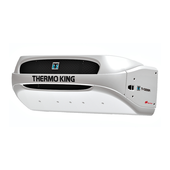
- Page 2 T-Series T-1200R, T-1200R Intermodal, T-1000R, T-800R, T-600R, T-500R T-1200R SPECTRUM,T-1000R SPECTRUM, T-800R SPECTRUM OPERATOR’S MANUAL TK60483-1-OP (Rev. 5, 09/14)
-
Page 3: Table Of Contents
TABLE OF CONTENTS Introduction ........4 The Multi-Temperature Display and Zone Indicators. - Page 4 TABLE OF CONTENTS Selecting CYCLE-SENTRY or Continuous Mode . . . 37 Selecting Sleep Mode......39 Pretrip ........41 Diesel/Electric Menu .
-
Page 5: Introduction
The manufacturer, Thermo King, assumes no All service requirements, major and minor, responsibility for any act or action taken on should be handled by a Thermo King dealer. the part of the owner or operator in the repair Performing pre-trip checks on a regular basis or operation of the products covered by this minimizes operating problems. -
Page 6: First Aid And Safety
Remove any contaminated clothing. Wash King technician. If you ever do have thoroughly with soap and water. Get medical At Thermo King we recognize the need to occasion to be working around the coils, use attention if irritation persists. preserve the environment and limit the... - Page 7 WARNING: Improperly installed battery could medical attention immediately. result in a fire or explosion! A Thermo King approved battery must be installed and properly CAUTION: Always cover battery terminals to secured to the battery tray.
-
Page 8: Unit Description
GENERAL DESCRIPTION and unit down time. The unit has a self check • Economy Mode The T-Series unit is a microprocessor based feature that can be run before the daily • Fahrenheit and Celsius Scales transport temperature control system that uses distribution route to identify possible •... -
Page 9: Unit Options
UNIT DESCRIPTION UNIT OPTIONS ELC (EXTENDED LIFE COOLANT) RECIPROCATING COMPRESSOR • Body Mount HMI Enclosure Systems The maintenance interval for ELC is 12,000 The T-500R (w/o bypass oil filter), T-600R, • DAS (Data Acquisition System)(except hours. A nameplate on the coolant expansion T-800R and 800R SPECTRUM feature the tank identifies units with ELC (see “Safety reliable TK214 four-cylinder reciprocating... -
Page 10: Cycle-Sentrytm System
UNIT DESCRIPTION T-1200R INTERMODAL Cycle Sentry Icon Box Temperature (Zone 1) Your T-1200R Intermodal unit uses the (Trailer) SR-3 control system to operate Setpoint (Zone 1) cooling, heating, and defrost functions. See Cooling (Zone 1) below some basic information on operating the Zone 1 Soft Key unit. -
Page 11: Defrost
UNIT DESCRIPTION CYCLE-SENTRY SYSTEM Defrost is accomplished by passing hot Manual Defrost refrigerant gas through the evaporator coil, thus Manual Defrost allows the operator to initiate a The CYCLE-SENTRY fuel saving system melting the frost (or ice). Melted frost drains defrost cycle by pressing the D key. -
Page 12: Electric Standby (Model 50 Units Only)
UNIT DESCRIPTION ELECTRIC STANDBY (MODEL 50 Automatic Phase Correction CAUTION: Do not remove expansion The control system features two motor UNITS ONLY) tank cap while the coolant is hot. contactors. This allows correct motor rotation The Electric Standby option allows the unit to regardless of phase rotation on the incoming be operated on either the diesel engine or power. - Page 13 UNIT DESCRIPTION UNIT PROTECTION DEVICES Sizes and functions are described in the Specifications section of this manual. High Pressure Cutout Switch (HPCO): T500R runs 3 electric evaporator fans. Independantly fused. This normally closed switch monitors the discharge pressure at the compressor.
- Page 14 UNIT DESCRIPTION Engine Oil Dipstick (on side of Alternator engine) Engine Compressor Coolant Expansion Tank Dehydrator (Filter-Drier) Sample T-Series Front Views Electric Motor Main Components in T-Series Unit (except T-500R)
- Page 15 UNIT DESCRIPTION Coolant Expansion Tank Dehydrator (Filter-Drier) Engine Compressor Electric Motor On/Off switch Alternator Main Components in T-500R Unit...
-
Page 16: Unit Operating Instructions Standard Tsr/Tsr-3 Hmi
Ready Input occurs. It will also glow if a 15 Standard HMI Control Panel is typically Clears Alarms pin Thermo King data cable is connected to located in the vehicle driver's compartment. It • Initiates and Indicates a Pretrip Test the serial port on the back of the controller may be located in the truck dashboard. - Page 17 Number of Alarms. Check Electric Ready Input occurs. It will also have occurred. If the display is light if a 15 pin Thermo King data cable is not flashing any alarms are The meaning of the display icons are shown in Check Alarms.
- Page 18 UNIT OPERATING INSTRUCTIONS STANDARD TSR/TSR-3 HMI CONTROLLER When the unit is turned on and If the setpoint has been changed Pressing the ON Key will turn the the Standard Display is shown, using the UP ARROW Key and/ unit on. pressing the UP ARROW Key or DOWN ARROW Key, pressing UP ARROW...
- Page 19 UNIT OPERATING INSTRUCTIONS STANDARD TSR/TSR-3 HMI CONTROLLER If the unit is turned on, pressing If the unit is turned on, pressing Pressing and holding the the HIGH SPEED LOCK-OUT the DEFROST Key will initiate a PRETRIP TEST Key for Key will activate High Speed manual defrost cycle if conditions 5 seconds will initiate either a Lock-Out.
-
Page 20: The Multi-Temperature Display And Zone Indicators
UNIT OPERATING INSTRUCTIONS STANDARD TSR/TSR-3 HMI CONTROLLER If a shutdown alarm occurred, IMPORTANT: If the unit is Alarm Code 28 Pretrip Abort will When one horizontal bar is configured as a 2 zone unit, be set and the unit will be shut present at Zone 3 will still appear down. -
Page 21: Starting The Diesel Engine
UNIT OPERATING INSTRUCTIONS STANDARD TSR/TSR-3 HMI CONTROLLER ALARMS In Figure 3, Zone 3 is being shown on the WARNING: NEVER USE STARTING FLUID. display. The box temperature in Zone 3 is 9.3°C When the engine is preparing to start, the TSR/ ALARM CODE NOTIFICATION and the setpoint is 10°C. -
Page 22: Pretrip Test
UNIT OPERATING INSTRUCTIONS STANDARD TSR/TSR-3 HMI CONTROLLER • Some alarms cannot be cleared using the • The unit will auto switch from Diesel Mode Standard Truck HMI Control Panel. These to Electric Mode or from Electric Mode to alarms must be cleared by maintenance Diesel Mode during a Pretrip Test if these personnel from the Maintenance or Guarded features are enabled and the auto switch... -
Page 23: Display Brightness
UNIT OPERATING INSTRUCTIONS STANDARD TSR/TSR-3 HMI CONTROLLER CHECKING TRUCK HMI CONTROL • Heat Check - The ability of the unit to heat in • If running a Pretrip Test on a truck loaded low speed is checked. with dry cargo, insure that proper airflow can PANEL SOFTWARE REVISION AND occur around the load. -
Page 24: Keypad Lockout
UNIT OPERATING INSTRUCTIONS STANDARD TSR/TSR-3 HMI CONTROLLER KEYPAD LOCKOUT When Keypad Lockout is turned on, only the ON and OFF Keys are functional. All other The Keypad Lockout feature allows the keys are locked out. Pressing any key other operator to lock the keypad to prevent than the ON Key and OFF Key will cause the tampering. -
Page 25: Unit Operating Instructions Premium Hmi Controller
UNIT OPERATING INSTRUCTIONS PREMIUM HMI CONTROLLER UNIT OPERATING INSTRUCTIONS PREMIUM HMI CONTROLLER The Premium Truck HMI (Human/Machine Interface) Control Panel is available as an option on TSR-3 Truck applications. It is used to operate the unit, display unit information and access all TSR-3 Maintenance and Guarded Access Menus. -
Page 26: Keys
UNIT OPERATING INSTRUCTIONS PREMIUM HMI CONTROLLER KEYS The keys on the left and right sides of the Sends a Start of Trip to the ServiceWatch data display are dedicated single function "hard" logger. HARD KEYS keys. DISPLAY The four keys under the display are "soft" keys. The keys on either side of the display are The display presents information to the The functions of these soft keys change... -
Page 27: Turning The Unit On And Off
THERMO KING Logo as the display initializes. Important: The ON key must be held down YES Key until the Thermo King Logo appears. If the Startup Screen The display will briefly show ON key is not held down long enough... -
Page 28: The Standard Display
UNIT OPERATING INSTRUCTIONS PREMIUM HMI CONTROLLER Should it be necessary to change to another Pressing the left soft key allows the user to language at any time, return to the Standard change the SETPOINT, and pressing the right Display and then press and hold the first and soft key accesses the MAIN MENU. -
Page 29: Operating The Unit In Single Zone Control Mode (Spectrum)
UNIT OPERATING INSTRUCTIONS PREMIUM HMI CONTROLLER The Two Zone Standard Display The Three Zone Standard Display Guarded Access/Main Menu Configuration menu. • If Single Zone Control operation is selected then all zones will be forced on and will control to the same setpoint. •... -
Page 30: Starting The Diesel Engine
UNIT OPERATING INSTRUCTIONS PREMIUM HMI CONTROLLER start. See STARTING THE ELECTRIC Electric motor starting is automatic in both MOTOR on the following pages for details. Continuous Mode and CYCLE-SENTRY CAUTION: The engine may start Mode. The motor will start as required when automatically any time the unit is turned on. -
Page 31: Main Menu Overview (Spectrum)
UNIT OPERATING INSTRUCTIONS PREMIUM HMI CONTROLLER MAIN MENU OVERVIEW MAIN MENU CHOICES (SPECTRUM) LANGUAGE - If more than one language is enabled, this will be the first menu item to Truck SR-2 SPECTRUM M/T Operator and appear. If only one language is enabled, this Main Menu. -
Page 32: Alarms
When the unit is turned on the display will appear if the unit does not feature optional SHUTDOWN ALARMS show the Thermo King Logo and then the Electric Standby or if the Diesel to Electric "Configuring System" message. If log alarm(s) Shutdown alarms will be set if continued Auto-switch feature is set YES. - Page 33 UNIT OPERATING INSTRUCTIONS PREMIUM HMI CONTROLLER (Light areas become dark and dark areas PREVENT ALARMS the alarm re-occurring, the alarm is auto become light.) cleared and the unit will run normally. Prevent Alarms are also indicated by a steady • The remote indicator alarm light (if installed) •...
- Page 34 • Alarm Code 24 Heating Cycle Fault Maintenance Menu or Guarded Access Menu: • Alarm Code 32 Refrigeration Capacity Low The Alarm Icon used in previous Thermo King • Alarm Code 03 Check Control Return Air controllers has been incorporated. If a Check...
- Page 35 UNIT OPERATING INSTRUCTIONS PREMIUM HMI CONTROLLER The Language Menu or Alarms Menu will appear. If the Language Menu appears press the NEXT key to show the Alarm Menu. When the Alarms Menu is shown press the SELECT key. Alarm Code 6 Help Key After the alarm situation is resolved press the A help message will appear.
-
Page 36: Datalogger
UNIT OPERATING INSTRUCTIONS PREMIUM HMI CONTROLLER DATALOGGER The first feature that appears is the Start of Trip. To send a Start of Trip to the The unit can be equipped with an optional DAS ServiceWatch Data Logger and DAS Data Data Logger if desired. -
Page 37: Mode
UNIT OPERATING INSTRUCTIONS PREMIUM HMI CONTROLLER Press the NEXT or PREVIOUS key to scroll Total number of IMPORTANT: If a programmable hourmeter is Zone 2 Run Time Hours: not enabled or the view for that hourmeter is through the enabled hourmeters. hours Zone 2 has run. -
Page 38: Selecting Cycle-Sentry Or Continuous Mode
UNIT OPERATING INSTRUCTIONS PREMIUM HMI CONTROLLER SINGLE ZONE CONTROL – MULTI If a Wakeup Time is selected the following The first mode change screen will appear. To features are available: choose that function, press the SELECT key. ZONE CONTROL (SPECTRUM) To Scroll thru the Mode Menu press the NEXT This feature allows the day of Day to Wake Up:... - Page 39 UNIT OPERATING INSTRUCTIONS PREMIUM HMI CONTROLLER The display then returns to the Mode Menu. In the example here the unit is currently running in Continuous mode. Pressing the Select key again allows the operator to change back to CYCLE-SENTRY mode operation. Select Key Select Key The Turn Off/Turn On CYCLE-SENTRY...
-
Page 40: Selecting Sleep Mode
UNIT OPERATING INSTRUCTIONS PREMIUM HMI CONTROLLER SELECTING SLEEP MODE The operator can now choose a Sleep Mode Wake-up Time or simply enter Sleep Mode Normal CYCLE-SENTRY mode starts and immediately. If NO is pressed the unit will stops the unit as required to maintain the immediately enter Sleep Mode. - Page 41 UNIT OPERATING INSTRUCTIONS PREMIUM HMI CONTROLLER To enter a Wake-up Time, verify the unit clock is set properly. Then press the YES key at the Sleep Mode menu. Confirm Hour Press Yes Key for Pretrip Test The display will now prompt the operator for The display will show SLEEP and the unit will the MINUTE the unit is to restart in normal start and stop as required to keep the engine...
-
Page 42: Pretrip
UNIT OPERATING INSTRUCTIONS PREMIUM HMI CONTROLLER PRETRIP CONDITIONS WHERE PRETRIP TESTS Pretrip Test Sequence Pretrip tests proceed in the order shown below. ARE NOT ALLOWED A Pretrip Test verifies unit operation. This A Full Pretrip Test includes all tests. A display allows a Pretrip Test to be selected and •... - Page 43 UNIT OPERATING INSTRUCTIONS PREMIUM HMI CONTROLLER PRETRIP TEST CONSIDERATIONS PERFORMING A PRETRIP TEST When performing a Pretrip Test, the following If a Pretrip Test is initiated with the engine shut issues should be considered. down a Full Pretrip Test will be performed. If a Pretrip Test is initiated with the engine or motor •...
-
Page 44: Diesel/Electric Menu
UNIT OPERATING INSTRUCTIONS PREMIUM HMI CONTROLLER DIESEL/ELECTRIC MENU The Diesel Mode/Electric Standby menu allows the operator to manually select diesel or electric mode operation. The unit can also be programmed to automatically select electric mode operation when standby power is available and to automatically select diesel Performing Cool Test mode operation if standby power fails or is... -
Page 45: Adjust Brightness
UNIT OPERATING INSTRUCTIONS PREMIUM HMI CONTROLLER NOTE: This screen will not appear if diesel to The unit will return to Diesel Mode operation. electric autoswitching is enabled. The unit can be programmed to automatically If the unit has standby power available and is switch to electric mode operation when standby turned on, the electric standby run screen will power is available. -
Page 46: Time
UNIT OPERATING INSTRUCTIONS PREMIUM HMI CONTROLLER The display brightness is changed to the new setting. TIME The system time and date is viewed using the Main Menu. Time and Date cannot be changed from the Main Menu. From the Standard Display, press the MENU key. -
Page 47: Tsr/Tsr-3 Alarm Codes
TSR/TSR-3 ALARM CODES TSR/TSR-3 ALARM CODES Code Description Operator Help Code Description Operator Help High Discharge If unit is shut down Engine Failed to If unit is shut down Note: Not all alarm codes are used with all Pressure repair immediately. Crank repair immediately. - Page 48 TSR/TSR-3 ALARM CODES Code Description Operator Help Code Description Operator Help Code Description Operator Help Heating Cycle The indicated zone is Refrigeration The indicated zone is Check Water If unit is shut down Fault not longer able to Capacity Low not longer able to Valve Circuit repair immediately.
- Page 49 TSR/TSR-3 ALARM CODES Code Description Operator Help Code Description Operator Help Code Description Operator Help Check Air Flow If unit is shut down Check If unit is shut down Ammeter Out of If unit is shut down repair immediately. Economizer valve repair immediately.
- Page 50 TSR/TSR-3 ALARM CODES Code Description Operator Help Code Description Operator Help Code Description Operator Help Data log EPROM If unit is shut down Check Suction Report alarm at end Check Loader #2 If unit is shut down Checksum Failure repair immediately. Pressure Sensor of the day.
- Page 51 TSR/TSR-3 ALARM CODES Code Description Operator Help Code Description Operator Help Code Description Operator Help Check condenser If unit is shut down Check High If unit is shut down Engine Run Time Report alarm at end inlet sol circuit repair immediately. Pressure Cut Out repair immediately.
- Page 52 TSR/TSR-3 ALARM CODES Code Description Operator Help Code Description Operator Help Code Description Operator Help Autoswitch Diesel Report alarm at end Out of Range Low Manually monitor Emission control to Electric of the day. load temperature. failure Disabled Report alarm at end Check Display Manually monitor of the day.
-
Page 53: Electric Standby Operation
ELECTRIC STANDBY OPERATION ELECTRIC STANDBY NOTE: The Model 50 control system automatically determines if diesel or electric OPERATION power is desired. See “See Starting the Electric Motor on Model 50 units are equipped with Electric page 19” or on page 28 in the Unit Operation Standby. -
Page 54: Care And Maintenance
CARE AND MAINTENANCE CARE AND MAINTENANCE 5. Belts 13. Remote Evaporators (SPECTRUM) • Visually inspect Evaporator(s) for damaged, The belts must be in good condition and loose, or broken parts. adjusted to the proper tension. PRE-TRIP INSPECTION • Check also for refrigerant leaks. 6. -
Page 55: Loading
CARE AND MAINTENANCE LOADING INSPECTING THE LOAD hot air drawn in. The unit may be run with the doors open if the truck is properly backed GENERAL INFORMATION into a refrigerated warehouse. 2. Perform final external and internal load 1. Inspect the cargo box for proper insulation. temperature checks. - Page 56 15 minutes and re-check the temperature. Wait 15 minutes more and if the temperature – Fan belt slipping or damaged. (Have the is still out of range, contact a Thermo King fan belt checked by a qualified mechanic.) dealer for service.
- Page 57 Examples are shown in the table below. Your Dealer will prepare a schedule to suit your specific needs. Note: T-500R has a different EMI to all other T-Series units and therefore must be presented at an authorised Thermo King dealer or service provider every 1000hrs for full service.
-
Page 58: Warranty
(including negligence and/or strict liability), or otherwise. 3. Any part of a unit which is repaired or supplied as a replacement under Thermo King’s Warranty will be installed without charge to buyer for labour or parts. - Page 59 WARRANTY 6. Thermo King’s warranty shall not apply to any unit which (i) has been so installed, maintained, repaired or altered as, in Thermo King’s judgement, to affect any integrity, (ii) has been subject to misuse, negligent handling or accident, or (iii) has been operated contrary to Thermo King’s printed Instructions.
-
Page 60: Specifications
-30 to 50 C (-22 to 122 F): SAE 5W-40 (Synthetic) Below -30 C (-22 F): SAE 0W-30 (Synthetic) Engine rpm: 1650 ± 25 rpm Low Speed Operation (T-Series) High Speed Operation 2200 ± 25 rpm T-500R 2250 ± 25 rpm... - Page 61 SPECIFICATIONS ENGINE (CONTINUED) Engine Oil Pressure 138 to 345 kPa (20 to 50 psig) in low speed 276 to 414 kPa (40 to 60 psig) in high speed Intake Valve Clearance 0.15 to 0.25 mm (0.006 to 0.010 in.) Exhaust Valve Clearance 0.15 to 0.25 mm (0.006 to 0.010 in.) Valve Setting Temperature 21 C (70 F)
-
Page 62: Engine Clutch - Hilliard
SPECIFICATIONS ENGINE (CONTINUED) CAUTION: Do not add “GREEN” or “BLUE-GREEN” conventional coolant to cooling systems using “RED” Extended Life Coolant, except in an emergency. If conventional coolant is added to Extended Life Coolant, the coolant must be changed after 2 years instead of 5 years. -
Page 63: Refrigeration System
12 volt, 37 amp/ 120 amp (SPECTRUM’S), brush type, Thermo King alternator Voltage Regulator Setting 13.95 to 14.4 volts @ 77 F (25 C) NOTE: Fuse F4 (Bypass resistor for Prestolite Alternator) must be removed for the Thermo King Alternator. -
Page 64: Electric Heater Strips (Optional)
SPECIFICATIONS ELECTRIC HEATER STRIPS (OPTIONAL) Number Watts 750 watts (each) Resistance 71 ohms (each) STANDBY POWER REQUIREMENTS Supply Circuit Breaker: T-500R, T-600R and T800 200-230/3/50-60 30 amps T-1000R, T-1200R, T-1200R Intermodal and SPECTRUM’S 50 amps 200-230/3/50-60 All 380-460/3/50-60 20 amps Extension Cord Size: Up to 15 m —... -
Page 65: Fuses
7.5A HPCO/Run Circuit F4 Remove fuse F4 for Model 30 units with Australian Bosch or Thermo King Alternators. Install fuse F4 for Model 50 units with Prestolite Alternator. F10 When fuse F10 is installed in the upper position the On/Off keys on the HMI turn the unit on and off. When fuse F10 is installed in the... -
Page 66: Electrical Components
SPECIFICATIONS ELECTRICAL COMPONENTS Component Current Draw (Amps) at 12.5 Vdc Resistance (Ohms) Glow Plugs (3) Each 2.3 ± 0.2 Fuel Solenoid: Pull In Coil 35 to 45 0.2 to 0.3 Hold In Coil 24 to 29 High Speed (Throttle) Solenoid Damper Solenoid Condenser Inlet Solenoid (CIS) Hot Gas Solenoid (HGS) - Page 67 SPECIFICATIONS Electrical Standby (Model 50 Units Only) T-500R, T-600R,T-800R and T-800R Spectrum Voltage/Phase/Frequency Horsepower Kilowatts Full Load Overload Relay (amps) Setting (amps) 230/3/50 1460 17.0 230/3/60 1765 19.4 400/3/50 1460 460/3/60 1765 Electrical Standby (Model 50 Units Only) T-1000R,T-1200R, T-1200R Intermodal, T-1000R SPECTRUM and T-1200R SPECTRUM Voltage/Phase/Frequency Horsepower...
-
Page 68: Serial Number And Refrigerant Label Locations
SERIAL NUMBER AND REFRIGERANT LABEL LOCATIONS SERIAL NUMBER AND REFRIGERANT LABEL LOCATIONS Write the unit model and unit serial number in the spaces provided in the following Emergency Cold Line chapter. This information is needed to service the unit. Laminated Unit Serial Number Plate Compressor Serial Number Location Refrigerant Type Label •...
Need help?
Do you have a question about the T-Series and is the answer not in the manual?
Questions and answers