
Related Manuals for Thermo King RD-MT


Summary of Contents for Thermo King RD-MT
- Page 1 RD-MT w/TK 3.95 TK 51730-1-MM (Rev. 0, 08/02) Copyright© 1999 Thermo King Corp., Minneapolis, MN, USA. Printed in USA.
- Page 2 If further information is required, Thermo King Corporation should be consulted. Sale of product shown in this manual is subject to Thermo King’s terms and conditions including, but not limited to, the Thermo King Limited Express Warranty. Such terms and conditions are available upon request.
- Page 3 Ester compressor oil in tightly sealed containers. If Polyol Ester oil becomes contaminated with moisture or standard oils, dispose of properly–DO NOT USE. When servicing Thermo King R-404A unit, use only those service tools certified for and dedicated to R-404A refrigerant and Polyol Ester compressor oils.
-
Page 5: Table Of Contents
Table of Contents List of Figures ................11 Safety Precautions . - Page 6 Table of Contents Operating Instructions (continued) Starting the Unit—Electric Operation ............52 Starting Zone 2 Evaporator .
- Page 7 Table of Contents Engine Maintenance (continued) Fuel Filter Replacement ..............86 Electric Fuel Pump .
- Page 8 Table of Contents Refrigeration Service Operations (continued) Accumulator ................119 Removal .
- Page 9 Table of Contents Remote Evaporator Maintenance Inspection Schedule ........149 Remote Evaporator Unit Description .
- Page 10 Table of Contents...
-
Page 11: List Of Figures
List of Figures Figure 1: Typical Compartment Configurations ..........25 Figure 2: Spectrum Remote Evaporator . - Page 12 List of Figures Figure 59: High Pressure Cutout Manifold ........... . 109 Figure 60: Set-up and Test Evacuation Equipment .
-
Page 13: Safety Precautions
Safety Precautions General Practices Auto Start/Stop 1. Always wear goggles or safety glasses. CAUTION: The unit may start Refrigerant liquid, refrigeration oil, and automatically and at any time when the battery acid can permanently damage the eyes. unit On/Off switch is in the On position. 2. -
Page 14: Refrigeration Oil
Safety Precautions Refrigeration Oil The following procedures must be rigidly adhered to when servicing units to avoid microprocessor Observe the following precautions when working damage or destruction. with or around synthetic or polyol ester refrigerant 1. Disconnect all power to the unit. oil: 2. -
Page 15: Welding Of Units Or Truck Bodies
Safety Precautions Welding of Units or Truck Bodies Precautions When electric welding is to be performed on any 1. Be certain the Unit On/Off switch is turned portion of the temperature control unit, truck or Off before connecting or disconnecting the truck chassis when the temperature control unit is standby power plug. -
Page 16: Low Voltage
Safety Precautions If the victim must be removed from a live circuit, pull the victim off with a non-conductive material. Use the victim’s coat, a rope, wood, or loop your belt around the victim’s leg or arm and pull the victim off. -
Page 17: Specifications
Specifications Engine—TK 3.95 Engine TK 3.95 Fuel Type No. 2 Diesel fuel under normal conditions No. 1 Diesel fuel is acceptable cold weather fuel Oil Capacity: Crankcase & Oil Filter 13 quarts (12.3 liters) w/Bypass Oil Filter 14 quarts (13.2 liters) Fill to full mark on dipstick Oil Type* API Type CF-4 or CG-4 or better multigrade oil... -
Page 18: Engine-Tk 3.95
** Thermo King synthetic oil is compatible with petroleum lubricants so there is no danger if accidental mixing occurs or if an emergency required addition of petroleum oil. Mixing is not recommended, however, since it will dilute the superior... -
Page 19: R-404A Refrigeration System
Specifications R-404A Refrigeration System Compressor Model Thermo King X426 Refrigerant Charge 13 lb. (5.9 kg) R-404A Compressor Oil Charge 4.3 quarts (4.1 liters)* Compressor Oil Type Solest 35 TK No. 203-413 (Ester base) required Throttle Valve Setting 18 to 20 psig (124 to 138 kPa) -
Page 20: Belt Tension
Specifications Belt Tension Tension No. on TK Gauge 204-427 New Belt Field Reset Engine/Compressor 75 ± 3 70 ± 3 Compressor/Jackshaft (Electric Motor) 72 ± 3 67 ± 3 Compressor/Evaporator Fan/Alternator 55 ± 5 50 ± 5 Water Pump 50 ± 5 50 ±... -
Page 21: Electrical Components
Specifications Electrical Components Current Draw (Amps) Resistance— at 12.5 Vdc (Ohms) Glow Plug 7 to 8.3 1.5 ± 0.15 Fuel Solenoid: Pull In 18 to 36 0.3 to 0.7 Hold In 0.49 to 0.6 22 to 26 High Speed Solenoid Condenser Inlet Solenoid (15 watt) 10.4 Receiver Tank Pressure Solenoid (15 watt) - Page 22 Specifications...
-
Page 23: Maintenance Inspection Schedule
Maintenance Inspection Schedule A closely followed maintenance program will The schedule covers units with conventional help to keep your Thermo King unit in top coolant and units with ELC. operating condition. The following general schedule is provided to assist in monitoring that maintenance. - Page 24 Maintenance Inspection Schedule 1,200 Annual/ Inspect/Service These Items trip Hours Hours 3,000 NOTE: The 1,200 hour maintenance interval may be extended to Hours 2,000 hours or 1 year (whichever occurs first) when equipped with EMI fuel filter and EMI bypass oil filter. Electrical •...
-
Page 25: Unit Description
14.7 continuous horsepower condenser. (10.96 kW) at 2400 RPM. A centrifugal clutch The RD-MT operates under the control of a TG-V (mounted on the engine) and a belt drive system microprocessor controller. The In-Cab Dual-Temp transfer energy to the compressor, the condenser Controller provides safe, convenient operation fan, and the alternator. -
Page 26: Spectrum Remote Evaporator
Unit Description Microprocessor Controller The RD-MT will operate in one of the following modes depending on the air temperature in the TG-V truck’s cargo compartment as sensed by the Thermo King has applied the newest Microprocessor Controller TG-V: technological advances to develop a... -
Page 27: Unit Operation
Unit Description Unit Operation • The flow of refrigerant through the system is controlled by the solenoid valves and the Several operating characteristics of the system check valves. during engine operation are: • The solenoid circuits are switched by the •... -
Page 28: Reading Mode Of Operation Charts
Unit Description Reading Mode of Operation Charts The Mode of Operation Charts use the status of the 1K and 2K relays (or the R1K and R2K relays) to show the thermostat demand: D = De-energized (0 volts) E = Energized (12 volts) High Speed Cool—1K = D and 2K = E Low Speed Cool—1K = D and 2K = D Low Speed Heat—1K = E and 2K = D... -
Page 29: Mode Of Operation Charts
Unit Description Mode of Operation Charts Engine Operation* Two Compartment (with Door Sentry II) Thermostat Relays F Door R Door Solenoids Fans Fans Speed Zone 1 Zone 2 F-COOL CLOSED CLOSED HIGH R-COOL F-COOL CLOSED CLOSED R-COOL F-HEAT CLOSED CLOSED R-HEAT F-HEAT CLOSED CLOSED HIGH... - Page 30 Unit Description Engine Operation Single Compartment (with Door Sentry II) (One Large Compartment Using Both Evaporators)* Thermostat Relays F Door R Door Solenoids Fans Fans Speed Zone 1 Zone 2 F-COOL CLOSED CLOSED HIGH R-COOL F-COOL CLOSED CLOSED R-COOL F-HEAT CLOSED CLOSED R-HEAT F-HEAT...
- Page 31 Unit Description Electric Operation* Two Compartment (with Door Sentry II) Thermostat Relays F Door R Door Elec. Solenoids Fans Fans Motor Zone 1 Zone 2 F-COOL CLOSED CLOSED D D D COOL COOL R-COOL F-COOL CLOSED CLOSED D D D COOL COOL R-COOL...
- Page 32 Unit Description Electric Operation Single Compartment (with Door Sentry II) (One Large Compartment Using Both Evaporators)* Thermostat Relays F Door R Door Elec. Solenoids Fans Fans Motor Zone 1 Zone 2 F-COOL CLOSED CLOSED D D E COOL COOL R-COOL F-COOL CLOSED CLOSED D D E...
-
Page 33: Zone 1 Cool And Zone 2 Cool
Unit Description Zone 1 Suction Line Check Valve (SLCV)— Zone 1 Cool and Zone 2 Cool Open High pressure refrigerant vapor leaves the Zone 1 Suction Line Solenoid (SLS)—Open compressor and flows through the open CIS to the condenser where the refrigerant condenses into Zone 1 Hot Gas Solenoid (HGS)—Closed high pressure liquid. -
Page 34: Zone 1 Cool And Zone 2 Heat
Unit Description Zone 1 Suction Line Solenoid (SLS)—Open Zone 1 Cool and Zone 2 Heat Zone 1 Hot Gas Solenoid (HGS)—Closed The CIS is closed so high pressure refrigerant vapor leaves the compressor and flows through Zone 2 Evaporator the Zone 2 hot gas line and the open RHGS into the Zone 2 evaporator. -
Page 35: Operating Modes
Unit Description At setpoints above 15 F Operating Modes Zone 2 Evaporator: (-9.4 C), the Zone 2 evaporator operates in the High Speed Heat is normally locked out at following modes. setpoints below 15 F (-9.4 C). • Cool Engine, Continuous Run—Two •... -
Page 36: Engine, Continuous Run-Single Compartment Operation
Unit Description At setpoints above 15 F Engine, Continuous Run—Single Zone 2 Evaporator: (-9.4 C), the Zone 2 evaporator operates in the Compartment Operation following modes. At setpoints above 15 F Zone 1 Evaporator: (-9.4 C), the Zone 1 evaporator operates in the •... -
Page 37: Cycle-Sentry Operation
Unit Description CYCLE-SENTRY Operation Units that are equipped with the CYCLE-SENTRY option will shut down when both evaporators are in Null. The unit starts when either thermostat calls for high speed or when Defrost is initiated in either evaporator. Features of the CYCLE-SENTRY system are: •... -
Page 38: Electric Operation
Electric Operation Defrost Operation During electric operation, the electric motor will As the RD-MT is operated to cool the cargo box, stop when both evaporators are in Null. The frost will gradually build up on the evaporator electric motor will not start until one of the coils. -
Page 39: Serial Number Locations
Unit Description Three methods of Defrost initiation are available: Microprocessor Controller TG-V: Microprocessor Controller is programmed to automatically initiate a Defrost cycle every 4 hours during pulldown until return air temperature is in-range (between approximately 7 degrees above and 7 degrees below setpoint). The Air Switch automatically places Air Switch: the unit into Defrost when the frost accumulation... -
Page 40: Design Features
Unit Description Design Features Unit Model Unit Model Unit Model RD-MT 30 NAD RD-MT 50 NAD RD-MT 50 EEC (920000) (920001) (920002) TK 3.95 Diesel Engine • • • X426 Compressor with Oil Filter • • • Electric Standby Motor 230/3/60 •... -
Page 41: Unit Photographs
Unit Description Unit Photographs ARD026 Figure 12: Front View AGA267 Figure 13: Top View... -
Page 42: Figure 14: Engine Side Door Open
Unit Description ARD041 Figure 14: Engine Side Door Open... -
Page 43: Figure 15: Tg-V Multi-Temp Control Box
Unit Description 1. One Temp/Two Temp Switch 6. Preheat/Start Switch 2. Auto Start/Stop - Continuous Run Switch 7. Run Hourmeter (Optional on Model 50) 3. Stop Start Light (Optional) 8. Electric Operation Hourmeter (Optional on Model 50) 4. Engine Reset 9. -
Page 44: Figure 16: Tg-V In-Cab Controller For Multi-Temp Compartment Units
Unit Description AEA2127 Temperature Display (Zone 1) Temperature Display (Zone 2) Power Cord Indicator Light (Model 50) EFROST 10. Z EFROST NTER 12. W ELECT HISPER Figure 16: TG-V In-Cab Controller for Multi-Temp Compartment Units... -
Page 45: Operating Instructions
Operating Instructions Unit Controls • The Microprocessor Controller calls for heating or cooling. TG-V Multi-Temp Control Box • Manual Defrost initiated. WARNING: Do not operate the unit until • Engine block temperature drops below you are completely familiar with the 30F (-1 C). -
Page 46: Tg-V In-Cab Controller For Multi-Compartment Units
Operating Instructions TG-V In-Cab Controller for Other situations which may cause the engine reset Multi-Compartment Units to open are: • Engine runs out of fuel. WARNING: Do not operate the TG-V until you are completely familiar with the • On/Off switch is left on accidentally without meaning of each display symbol, and the the engine being started. -
Page 47: Electric Standby Power Receptacle
Operating Instructions Used to select the various displays Key: During the normal operation, the standard display ELECT which can appear on the screen. is on the screen. Used to increase setpoint temperature Key: Return Air Temperature is factory standard when the setpoint symbol is on the screen. display setting (can be changed). -
Page 48: Other Controls
Operating Instructions Other Controls Unit Protection Devices A temperature Defrost Termination Switches: A thermal type manual reset Engine Reset Switch: sensitive switch is mounted on each evaporator switch protects the engine. The reset switch coil. It is used to control Defrost. The switch contains a heater coil that is attached to a sensor closes when the evaporator temperature drops to switch in the engine oil system, engine coolant... -
Page 49: Unit Operation
Operating Instructions The engine low The engine oil level should be at the Engine Low Oil Pressure Cutout: Engine Oil: oil pressure cutout is a pressure sensitive switch FULL mark on the dipstick. Never overfill. located in the engine oiling system. This switch Check coolant level gauge for the correct Coolant: will trip the Engine Reset and stop the engine if... -
Page 50: Starting The Unit-Auto Start Diesel Operation
CYCLE-SENTRY Equipped Units thermostat demand. The unit runs The Thermo King CYCLE-SENTRY system is continuously until it is turned off manually. designed to save refrigeration costs. The savings The start sequence, once initiated, is the vary with the commodity, ambient temperatures same for both systems. - Page 51 Operating Instructions Examples of Products Normally CYCLE-SENTRY Operation Acceptable for CYCLE-SENTRY Operation With the selector switch placed in the • Frozen foods (in adequately insulated trailers) CYCLE-SENTRY position, the CYCLE-SENTRY system shuts down the unit • Boxed or processed meats when the compartment temperature reaches the •...
-
Page 52: Starting The Unit-Electric Operation
Operating Instructions NOTE: A unit that is equipped with 7. At the end of the preheat period, the engine CYCLE-SENTRY should be manually started if will begin cranking. The glow plugs remain it has been turned off long enough for the engine energized during the cranking period. -
Page 53: Starting Zone 2 Evaporator
Starting Zone 2 Evaporator 4. Products should be pre-cooled before loading. 1. Start the condensing unit Zone 2 will Thermo King units are designed to maintain automatically be on. loads at the temperature at which they were loaded. Transport refrigeration units are not 2. -
Page 54: Post Trip Checks
Operating Instructions Post Trip Checks 1. Wash the unit. 2. Check for leaks. 3. Check for loose or missing hardware. 4. Check for physical damage to the unit. -
Page 55: Electrical Maintenance
Thermo King P/N NOTE: Units manufactured with 204-615 (FLUKE 23) digital multimeter and a CYCLE-SENTRY and alternators with integral Thermo King P/N 204-613 amp clamp or an regulators MUST use replacement alternators equivalent. with integral regulators. -
Page 56: Battery
Electrical Maintenance NOTE: All voltage readings should be taken 14. Connect a jumper wire between the F2 between the negative battery terminal, or a good terminal and a chassis ground. This will full chassis ground, and the terminals indicated, field the alternator. unless stated otherwise. -
Page 57: Unit Wiring
Electrical Maintenance Unit Wiring Engine Reset Switch Inspect the unit wiring and the wire harnesses The engine is protected by a manual reset switch. during scheduled maintenance inspections for The reset switch is attached to a two sensors. One loose, chaffed, or broken wires to protect against sensor switch is in the engine oil system, the other unit malfunctions due to open or short circuits. -
Page 58: High Water Temperature Switch (Hwt)
Electrical Maintenance High Water Temperature Switch Circuit Breakers (HWT) Main Circuit Breaker The HWT will close and trip the reset switch if This 50 amp auto reset circuit breaker protects the coolant temperature is greater than 220 F 2A, the main power circuit. (104 C). -
Page 59: Unloading Timer (Eut)
Electrical Maintenance Unloading Timer (EUT) Testing the Unloading Timer The unloading timer energizes the unloading relay 1. Remove the CYCLE-SENTRY module from (EUR) for approximately 20 seconds when the the option board to prevent the Auto Start engine or the electric motor is first started to system from preheating and cranking the reduce the load. -
Page 60: Control Circuit Fuse
Electrical Maintenance Defrost System 6. Place the On/Off switches in the On position and press the key. CAUTION: This unit is equipped with 7. Check for battery voltage at the 7KB wire in Auto Start. It will start automatically if the the main wire harness. -
Page 61: Zone 1 Evaporator Defrost Cycle Diesel Operation
Electrical Maintenance Zone 1 Evaporator Defrost Cycle Zone 1 Evaporator Defrost Cycle Diesel Operation Checkout Procedure The Defrost cycle can be initiated with the ANUAL CAUTION: This unit is equipped with key, by the air switch, or by the defrost EFROST Auto Start. - Page 62 Electrical Maintenance Zone 1 Evaporator Does Not Defrost Zone 1 Evaporator Sticks In Defrost Indefinitely 1. Check the evaporator temperature: If the unit remains stuck in Defrost indefinitely, Make sure the evaporator temperature is check the defrost relay, the 11 circuit and the actually below 42 F (6 C) if the unit will not TG-V Controller.
-
Page 63: Zone 2 Evaporator Defrost Cycle Diesel Operation
Electrical Maintenance 1. Check the evaporator temperature: Initiating the Defrost cycle energizes the Zone 2 defrost relays, RD and RDR4. When RD is Be sure the evaporator temperature is actually energized, it energizes the RHGS circuit, which above 52 F (11 C) if the unit will not terminate energizes the RHGS and the 26 circuit. -
Page 64: Figure 20: Defrost Relay Locations
Electrical Maintenance Zone 2 Evaporator Does Not Defrost 3. Check for an open in the R12 circuit between the defrost termination switch and the TG-V 1. Check the evaporator temperature: controller. If the 12 circuit is not open, move Make sure the evaporator temperature is to step 4. - Page 65 Electrical Maintenance Zone 2 Evaporator Will Not Terminate Zone 2 Evaporator Continuously Fails to Defrost Terminate Defrost In Less than 45 Minutes If the defrost termination switch does not If the unit continually fails to complete the terminate Defrost less than 45 minutes after Defrost cycle in less than 45 minutes, and cycles Defrost was initiated, the TG-V Controller should between Cool and Defrost, check the evaporator...
-
Page 66: Defrost System Components
Electrical Maintenance Defrost System Components 2. Connect the negative lead of the switch to the negative battery terminal. Defrost Termination Switches 3. Raise the temperature of the defrost Each electronic defrost termination switch uses termination switch above 52 F (11 C). The solid state components to control the Defrost light should be off indicating an open switch. -
Page 67: Figure 22: Air Switch Testing And Adjustment
Electrical Maintenance 2. Disconnect one wire at the switch terminal. until the switch closes and the continuity Connect a test light or continuity tester to the tester indicates a completed circuit with the two terminals used on the switch. correct reading. Release the pressure. 3. -
Page 68: Fan Speed Control
Diagnosis Manual for all operation and diagnosis evaporator coil goes on the hose fitting on the procedures. The RD-MT is not presently included side of the air switch stamped BLACK. The in that manual but the systems are similar. -
Page 69: Option Board Jumpers
Electrical Maintenance Option Board Jumpers The option board has three 7.5 amp fuses that are used as jumpers to configure the board for different applications. If these jumpers are not in the correct positions, the unit may not function properly. The correct jumper positions for the unit are: J1—Position A, J2—Position A, J3—Position A. -
Page 70: Multi-Temp Relay Board
Electrical Maintenance Multi-Temp Relay Board The multi-temp relay board is located inside the control box. The thermostat relays and the associated control relays are located on the multi-temp relay board. The component locations are shown in the following illustration. AEA623 Zone 2 Heat/Cool Relay (R1K) 6. -
Page 71: Ac Components
Electrical Maintenance AC Components The In-Cab TG-V functions similarly to the standard unit mounted TG-V. However, the In-Cab TG-V Controller also has the following CAUTION: The unit uses high voltage additional features: alternating current (ac) during electric operation. Lethal voltage potentials can •... -
Page 72: Figure 26: Connecting Tester To Controller
Electrical Maintenance Field Test Procedure for 4. Press the key to display the setpoint(s) ELECT Multi-Temperature In-Cab TG-V and adjust the setpoint(s) to 80 F (27 C). Both Controllers setpoints must be adjusted to 80 F (27 C) to properly test the multi-temperature controller. Use tester P/N 204-831. -
Page 73: Figure 27: Connector On Back Of Multi-Temperature In-Cab Tg-V
Electrical Maintenance Connector Pins for Multi-Temperature In-Cab TG-V Pin # Circuit Code Harness Wire Color Code Circuit Description WHT/BLK/RED Zone 2 Unit On/Off WHT/VOIL Zone 2 Unit High Speed Relay WHT/ORG Battery Positive BLUE Not Used YELLOW Zone 2 Unit Heat Relay WHT/BLK/ORG Battery Positive WHT/BLK/YEL... -
Page 74: Door Sentry Ii
Electrical Maintenance Door Sentry II Opening Both Zone 1 and Zone 2 Doors Door Sentry II is a factory option that is designed Because power to operate the coils of relays XK1, to improve temperature control when the doors XK2 XK3 and XK4 is removed when the Zone 2 are opened during delivery. - Page 75 Electrical Maintenance Door Sentry-II Operation Modes Zone 1 Zone 2 Zone 1 Door Open Zone 2 Door Open Both Doors Open HS Cool Cool Unit goes to low speed, All power to Zone 2 unit Zone 1 unit ERC disabled. damper solenoid control circuits and Zone 1 unit runs normal.
- Page 76 Electrical Maintenance...
-
Page 77: Engine Maintenance
Thermo King’s maintenance Some of the oil supplied to the main bearings recommendations. flows through passages in the crankshaft to the NOTE: The new EMI 2000 oil filters and new connecting rod bearings. -
Page 78: Engine Oil Change
Engine Maintenance Oil pressure is affected by oil temperature, oil viscosity, and engine speed. Low oil pressure can usually be traced to the lack of oil, a faulty oil pressure control valve, loose connections in the lubrication system, or worn bearings. Low oil pressure is not normally caused by a faulty oil pump. -
Page 79: Oil Bath Type
Engine Maintenance occurs first. It cannot be interchanged with air The air cleaner removes abrasive material from filter elements used on previous Thermo King the air entering the engine. The air cleaner must truck units. be kept clean and open so that the air can pass freely. -
Page 80: Figure 32: Dry Air Cleaner (Optional)
Engine Maintenance Air Filter Box Air Filter Air Filter Cover Figure 32: Dry Air Cleaner (Optional) An air restriction indicator is installed in the air intake elbow. Visually inspect the restriction indicator periodically to assure the air filter is not restricted. -
Page 81: Engine Cooling System
Engine Maintenance Engine Cooling System All water cooled engines are shipped from the factory with a 50% permanent type antifreeze The engine uses a closed, circulating type, concentrate and 50% water mixture in the engine pressurized cooling system. Correct engine cooling system. -
Page 82: Elc (Extended Life Coolant)
To upgrade new production engines for ELC use, The following are the Extended Life Coolants all water pump seal bellows were changed from currently approved by Thermo King for use in NBR to HNBR elastomer, and the o-rings ELC units for five years or 12,000 hours: upgraded from NBR to EPDM elastomer. -
Page 83: Figure 36: Accumulator Tank Drain
Engine Maintenance Antifreeze Maintenance Procedures As with all equipment containing antifreeze, periodic inspection on a regular basis is required to verify the condition of the antifreeze. Inhibitors become worn out and must be replaced by changing the antifreeze. Change green or blue-green engine coolant every two years. -
Page 84: Engine Fuel System
Engine Maintenance Bleeding Cooling System Engine Fuel System After filling the radiator, run the unit up to The fuel system used on the TK 3.95 diesel engine operating temperature to check for overheating is a high pressure system used in conjunction with and coolant level and allow the air to be purged a prechamber. -
Page 85: Figure 38: Fuel System
Engine Maintenance AEA628 Fuel Injection Pump Fuel Pickup Tube Fuel Filter Electric Fuel Pump Figure 38: Fuel System... -
Page 86: Bleeding The Fuel System
Engine Maintenance Thermo King recommends that any major 3. Energize the electric fuel pump by placing the injection pump or nozzle repairs be done by a On/Off switches in the On position and quality diesel injection service specialty shop. The pressing the key. -
Page 87: Electric Fuel Pump
Engine Maintenance Electric Fuel Pump If pump does not operate, check for: • Ground to the frame of the TK unit Operation • Clean and tighten electrical connections The electric fuel pump must be mounted next to • The pump voltage and polarity. It must be the the fuel tank. -
Page 88: Fuel Solenoid System
Engine Maintenance Fuel Solenoid System The fuel solenoid is located on the end of the injection pump. It contains two coils: the pull-in coil, and the hold-in coil. The pull-in coil draws approximately 18 to 25 amps at 12 volts. The hold-in coil draws approximately 1 amp at 12 volts. -
Page 89: Fuel Solenoid Timer Operation
Engine Maintenance Fuel Solenoid Timer Operation energized momentarily by the fuel solenoid timer when the 8D circuit is first energized. After The fuel solenoid hold-in coil is connected to the approximately 2.5 seconds, the fuel solenoid timer 8D circuit. The fuel solenoid relay coil is also de-energizes the fuel solenoid relay by opening connected to the 8D circuit and it is grounded the circuit to ground. -
Page 90: Troubleshooting The Fuel Solenoid System
Engine Maintenance Troubleshooting the Fuel Solenoid a. If battery voltage is not present on the 8D System circuit, check the 8D circuit and the related circuits and components for a fault. NOTE: The fuel solenoid pull-in coil may require 18 to 25 amps to turn on the fuel. The b. -
Page 91: Figure 45: Relay Socket Terminal Identification
Engine Maintenance 10. Test the hold-in coil. a. Energize the hold-in coil by placing a jumper between the red wire (8D—pin A) in the fuel solenoid connector and the 2 terminal at the control circuit. b. Momentarily energize the pull-in coil by placing a jumper between the white wire AEA634 (8DP—pin B) in the fuel solenoid... -
Page 92: Fuel Solenoid Replacement
Engine Maintenance Fuel Solenoid Replacement Engine Speed Adjustments 1. Disconnect the 20 wire from the reset switch When the diesel engine fails to maintain the to prevent the reset switch from tripping. correct engine speeds, check the following before adjusting the speed: 2. -
Page 93: Injection Pump
Engine Maintenance 4. Turn the solenoid rod to change the engine 5. Place the solenoid rod back in the eye bolt and speed. Turn the solenoid rod clockwise to check the engine speed. reduce the engine speed. Turn the solenoid rod 6. -
Page 94: Injection Pump Installation
Engine Maintenance Injection Pump Installation CAUTION: The cylinders on the engine 1. Replace the shim set if it has been damaged are numbered from the flywheel end to the during the pump removal. New shims are water pump end. The number 1 cylinder is supplied in sets. -
Page 95: Figure 48: Timing Marks
Engine Maintenance 4. Remove the CYCLE-SENTRY module from 6. Place the On/Off switches in the On position the option board to prevent the Auto Start and press the key to energize the fuel system from preheating and cranking the solenoid and the fuel pump. engine. -
Page 96: Timing Individual Cylinder Injection
Engine Maintenance Timing Individual Cylinder Injection Fuel Limit Screw and Maximum Speed Stop Screw This procedure should be used when a poor running engine has had all possible problems The fuel limit screw and the maximum speed stop checked but continues to run badly. If the screw are both covered with anti-tamper caps and injection pump has been repaired or replaced, the are not adjustable. -
Page 97: Figure 50: Adjusting The Valve Clearance
Engine Maintenance 4. Check the valve clearance of both valves for 9. Check and adjust both valves for the number 3 the number 1 cylinder with a feeler gauge. The cylinder. valve clearance for both the intake valve and 10. Rotate the engine in the normal direction of the exhaust valve should be 0.006 to 0.010 in. -
Page 98: Engine Mounts
Engine Maintenance Engine Mounts The engine mounting system contains three vibration mounts and two snubber mounts. 0.20 Air Gap Between Lower Snubber and Engine Bracket When Assembled (Snubbers Only) Figure 51: Engine Mounting Components... -
Page 99: Belts
Engine Maintenance Restraining Bracket (91-8363) Vibration Mount (91-2281) Bracket Screw (55-3486) 10. Engine Screw (55-2914) Belleville Washer (55-7123) Engine Screw (55-4794) Nut (55-2559) 12. Special Washer (55-3594) Nut (55-2166) 13. Special Washer (55-5871) Belleville Washer (55-7123) 14. Mount Screw (55-3048) Vibration Mount (91-3908) 15. -
Page 100: Engine-Compressor Belt Adjustment
Engine—Compressor Belt a. The belt tension should be set at a reading Adjustment of 70 ± 3 on the Thermo King Belt Tension Gauge. 1. Loosen the idler pulley mounting bolt. b. The belt should deflect 1/2 in. (13 mm) at 2. -
Page 101: Figure 53: Belt Arrangement
Engine Maintenance AEA638 Engine—Compressor Belt Compressor—Jackshaft/Electric Motor Belt Compressor—Alternator Belt Water Pump Belt Figure 53: Belt Arrangement... -
Page 102: Compressor-Alternator Belt Adjustment
3. Tighten the alternator pivot bolt, the alternator 2. Turn the alternator adjustment nut to obtain a mounting bolt, and the alternator bracket reading of 50 ± 5 on the Thermo King Belt mounting bolts. Tension Gauge or 1/2 in. (13 mm) deflection... -
Page 103: Refrigeration Maintenance
(See evacuation should always be practiced. attached tool list and evacuation procedures.) See the diagram of the Thermo King Evacuation The primary objective of evacuation is to bring Station and note the location of the valves. -
Page 104: Figure 55: Evacuation Station
Refrigeration Maintenance AGA654 Two Stage Vacuum Pump Thermistor To 110 Vac Power Calibration Standard Vacuum or Micron Gauge Figure 55: Evacuation Station... -
Page 105: Figure 56: Vacuum Gauge
Refrigeration Maintenance 100 Microns 500 Microns 1000 Microns 2500 Microns 5000 Microns 20,000 Microns Atmospheric Pressure Calibration Adjustment Screw Example: Meter needle shown at calibration position when Calibration Standard specifies 0.15 mm Hg. Figure 56: Vacuum Gauge... -
Page 106: Refrigerant Charge
Refrigeration Maintenance Refrigerant Charge Testing the Refrigerant Charge with a Loaded Truck Testing the Refrigerant Charge with 1. Install a gauge manifold. an Empty Truck 2. Run both evaporators in Cool. If the unit has an insufficient charge of refrigerant, 3. -
Page 107: Adjusting The Refrigerant Level
Refrigeration Maintenance Moisture Indicating Sight 5. Observe the receiver tank sight glass and the unit’s discharge pressure. Glasses 6. By the time the discharge pressure drops The receiver tank is equipped with a moisture approximately 50 psi (345 kPa), the ball in the indicating sight glass. -
Page 108: Checking Compressor Oil
Refrigeration Maintenance Checking Compressor Oil The compressor oil should be checked when there is evidence of oil loss (oil leaks) or when components in the refrigeration system have been removed for service or replacement. To check compressor oil level with an ambient air Install a gauge temperature above 50 F (10 C): manifold on the compressor. -
Page 109: High Pressure Cutout Switch (Hpco)
Refrigeration Maintenance High Pressure Cutout Switch (HPCO) The HPCO is located on the compressor. If the discharge pressure rises above the switch setting 470 psi (3241 kPa) the HPCO opens and de-energizes the 8H circuit, which stops the unit. To test the HPCO, rework a gauge manifold as shown in the High Pressure Cutout Manifold illustration and use the following procedure. -
Page 110: Evacuating And Charging Procedures
Evacuating and Charging Set-up and Test Evacuation Equipment Procedures NOTE: The use of the Thermo King Evacuation Set-up Electrical Controls Station P/N 204-725 is recommended. 1. Remove the 20A wire from the engine low oil NOTE: Do not attempt to evacuate the unit until pressure switch. -
Page 111: Figure 60: Set-Up And Test Evacuation Equipment
Refrigeration Maintenance AEA647 Vacuum Gauge Vacuum Valve Thermistor Back Seated Isolation Valve—Open Figure 60: Set-up and Test Evacuation Equipment... -
Page 112: Unit Evacuation
Refrigeration Maintenance Unit Evacuation 7. Evacuate the system to 500 microns. Back seat the suction service valve and then NOTE: The electrical system must be energized continue to evacuate the system for one throughout this procedure. additional hour. 1. To prepare the unit for evacuation, recover NOTE: The presence of refrigerant in the any refrigerant to 0 psi (0 kPa). -
Page 113: Figure 61: Unit Evacuation
Refrigeration Maintenance AEA647 Vacuum Gauge Isolation Valve—Leave Closed for First 5 Minutes of Evacuation Thermistor Vacuum Valve Figure 61: Unit Evacuation... -
Page 114: Unit Charging
Refrigeration Maintenance Unit Charging 8. Observe the suction pressure and slowly open the gauge manifold hand valve to allow liquid NOTE: The electrical system must be energized refrigerant to flow into the suction service throughout this procedure. valve. Control the liquid flow so the suction 1. -
Page 115: Figure 62: Unit Charging
Refrigeration Maintenance AEA647 Isolation Valve—Closed Scale Vacuum Valve—Closed Refrigerant Evacuate or Purge Figure 62: Unit Charging... -
Page 116: Remove Evacuation Hoses
Refrigeration Maintenance Remove Evacuation Hoses 3. Back seat the suction service valve. 1. Run the unit with both evaporators in Cool 4. Remove the hoses from the receiver outlet and and with the receiver outlet and discharge discharge service valves. service valves back seated. -
Page 117: Refrigeration Service Operations
Refrigeration Service Operations NOTE: It is generally good practice to replace a. Disconnect the purge valve solenoid wires the filter drier whenever the high side is opened from the main wire harness. or when the low side is opened for an extended b. -
Page 118: Compressor
Refrigeration Service Operations Compressor Condenser/Radiator Coil Removal Removal 1. Pump down the compressor and equalize the 1. Remove the refrigerant charge. pressure to slightly positive. 2. Remove the grille assembly. 2. Loosen and remove the belts from the 3. Drain engine coolant and disconnect the compressor pulley. -
Page 119: Installation
Refrigeration Service Operations Installation High Pressure Relief Valve 1. Place the new o-rings in the ORS fittings on Removal the ends of the drier. 1. Remove the refrigerant charge. 2. Install the new drier and tighten the mounting screws and nuts. 2. -
Page 120: Installation
Refrigeration Service Operations Installation Condenser Inlet Check Valve Repair 1. Place the accumulator in the unit. 2. Install the mounting bolts loosely. Removal 3. Solder the refrigerant tubes to the accumulator 1. Remove the refrigerant charge. tank. 2. Remove the cap nut from the check valve, and 4. -
Page 121: Condenser Inlet Check Valve Replacement
Refrigeration Service Operations Condenser Inlet Check Valve Installation Replacement 1. Inspect the inside of the check valve body for damage or foreign particles which might Removal adhere to the seat and damage the new seat. If the body is damaged, replace the check valve. 1. -
Page 122: In-Line Check Valves
Refrigeration Service Operations In-Line Check Valves 7. Recharge the unit with the proper refrigerant and check the compressor oil (if pumped This unit uses some in-line check valves. An down, open the refrigeration valves instead). in-line check valve is not repairable and must be replaced if it fails. -
Page 123: Purge Valve (Pv)
Refrigeration Service Operations Purge Valve (PV) Disassembly 1. Remove the piston end cap (inlet). NOTE: Valves that have nylon seats must be disassembled before soldering. 2. Remove the cotter pin from the castle nut and remove the nut. Removal 3. Remove the spring and piston. 1. -
Page 124: Reassembly
Refrigeration Service Operations Reassembly 8. Inspect all the parts. a. Piston and cap for wear (scuff marks). 1. Install the bellows with the O-ring in the housing. b. Body for stripped threads. 2. Center the spring on the bellows shoulder. c. -
Page 125: Throttling Valve Installation
Refrigeration Service Operations AEA652 Screw—mtg plate Gasket—piston housing Plate—bellows end 10. Piston Gasket—end plate Spring—piston Washer—adjusting 12. Nut—adjusting Spring—bellows 13. Pin—cotter Bellows and Shaft—assy 14. Housing—piston O-Ring 15. Valve—Schrader Housing 16. O-Ring—valve to compressor Figure 69: Throttling Valve Assembly Throttling Valve Installation 3. -
Page 126: Compressor Oil Filter Change
Refrigeration Service Operations Compressor Oil Filter Change This unit is equipped with a compressor oil filter. The compressor oil filter should be changed when the drier is replaced (every two years or major repairs). 1. Pump down the low side and equalize the pressure to slightly positive. -
Page 127: Hilliard Clutch Maintenance
Hilliard Clutch Maintenance Large Truck Unit Centrifugal 104-257. Centrifugal clutch P/N 104-272 has three belt grooves and its engagement speed is Clutch Change (P/N 104-272) 600 ± 100 RPM. When this clutch is installed on a Beginning in the second quarter of 1997 most unit equipped with a two groove belt, the belt large truck units are equipped with centrifugal should be placed in the two grooves nearest to the... - Page 128 Hilliard Clutch Maintenance aea558 (3 belt grooves) Screw 10. Grease Seal Washer Roller Bearing Inner Race Snap-Ring 12. Pulley Housing Ball Bearing 13. Elastic Stop Nuts (6) Large & Small Spacers 14. Connector Link (6) Rolling Bearing 15. Spring (6) Lockwasher (12) 16.
-
Page 129: Clutch Maintenance
Hilliard Clutch Maintenance Clutch Maintenance Using an inspection mirror, inspect the clutch every 1000 hours of operation or yearly, whichever occurs first. If clutch removal is necessary, clean the shoes and drum, regrease bearings or replace if they are worn. Inspect anchor bushings, shoe lining and springs for wear and replace if necessary. -
Page 130: Assembly Procedure: Using New Bearings And Seal
Hilliard Clutch Maintenance 8. Remove inner race of roller bearing from the 2. Remove the inner race from the roller bearing, housing shaft. apply a small amount of Loctite #270 to race I.D. and press onto the housing shaft, seating NOTE: This race was Loctited and pressed against the step. -
Page 131: Figure 76: Clutch
Hilliard Clutch Maintenance 14. Place the hub and shoe assembly into the housing and place flatwasher over the bearing. 15. Apply Loctite #680 to 3/8-16x1 screw and install through washer into housing shaft. The housing and hub will be drawn together to the proper relative position as the screw is tightened. - Page 132 Hilliard Clutch Maintenance...
-
Page 133: Structural Maintenance
Structural Maintenance Unit Mounting Bolts Fan Location Periodically check and tighten all unit mounting When mounting the fan and hub assembly on the bolts. Torque the unit mounting bolts to 60 ft-in shaft, position the assembly in the orifice with 30 (81 N•m). - Page 134 Structural Maintenance...
-
Page 135: Mechanical Diagnosis
Mechanical Diagnosis Condition Possible Cause Remedy Unit switched On—indicator Batteries discharged Charge or replace batteries lights do not come on Reset switch tripped Check engine oil, coolant level, and CYCLE-SENTRY system (optional). Push in reset switch button Corroded battery connections Clean and tighten Circuit breaker tripping Check for short circuit in unit wiring... - Page 136 Mechanical Diagnosis Condition Possible Cause Remedy Engine stops after starting Air in injection pump Bleed fuel system Fuel filter obstructed Replace filter element High head pressure Eliminate cause of high head pressure Vent of fuel tank obstructed Unclog vent Reset switch trips Check engine oil, coolant level, and CYCLE-SENTRY system (optional).
- Page 137 Mechanical Diagnosis Condition Possible Cause Remedy Engine runs hot Dirty radiator Clean radiator Coolant level is low Add coolant Cooling system heavily scaled Clean cooling system Cylinder head gasket leaks Replace cylinder head gasket. Use correct gasket Faulty thermostat Check or replace the thermostat Loose or worn water pump belt Replace belt Oil pressure too low or drops...
- Page 138 Mechanical Diagnosis Engine Emits Excessive Smoke White Smoke Black Smoke Blue Smoke Fuel is not burning Excessive Fuel to Air Ratio Oil Consumption • Air or water in fuel • Type of fuel used • Poor compression • Incorrect timing •...
-
Page 139: Cycle-Sentry Diagnosis
CYCLE-SENTRY Diagnosis Condition Possible Cause Test Procedure Run relay will not energize when Open 7A circuit from selector switch Test 7A circuit required to run relay Defective selector switch Test circuit from 7M or 7MA to 7A on switch in the CYCLE position Open 7M or 7MA circuits Test 7M and 7MA circuits Open diode from 77, R7C, 7C or 7X... - Page 140 CYCLE-SENTRY Diagnosis Condition Possible Cause Test Procedure Unit cranks only after preheat has Defective engine temperature Test engine temperature thermistor occurred for approximately 6 thermistor minutes Open BL1 or BL2 wires from option Check BL1 and BL2 wires board to engine temperature thermistor Defective CSM Test or replace CSM...
-
Page 141: Electric Standby Diagnosis
Electric Standby Diagnosis Condition Possible Cause Remedy Unit switch On—indicator lights Battery discharged Charge or replace battery do not come on Circuit breaker open Check for short circuit in unit wiring Control circuit blown Replace control circuit Reset switch tripped Push reset switch button in Unit switch On—indicator lights Diesel/Electric switch on Diesel... - Page 142 Electric Standby Diagnosis Condition Possible Cause Remedy Contact chatter Low coil voltage Check voltage condition. Check momentary voltage dip during starting—low voltage prevents magnet sealing Defective or incorrect coil Replace coil Poor contact in control circuit Check auxiliary switch contacts and overload relay contacts.
-
Page 143: Refrigeration Diagnosis
Refrigeration Diagnosis Possible Causes • • • • Overcharge of refrigerant • • • • • • Shortage of refrigerant • • • • • No refrigerant • Air through condenser too hot (ambient) • Air flow through condenser restricted •... - Page 144 Refrigeration Diagnosis Possible Causes • • Expansion valve open too much • • Expansion valve closed too much • • Expansion valve needle eroded or leaking • • • Expansion valve partially closed by ice, dirt or wax • • •...
- Page 145 Refrigeration Diagnosis Possible Causes • • • • Leaky Zone 1 hot gas solenoid (HGS) • • Closed Zone 1 hot gas solenoid (HGS) • • • Leaky Zone 1 liquid line solenoid (LLS) • • • • • • Closed Zone 1 liquid line solenoid (LLS) •...
- Page 146 Refrigeration Diagnosis...
-
Page 147: Remote Evaporator Specifications
Remote Evaporator Specifications Refrigeration System Evaporator Coil Type Direct Expansion Refrigerant Type R404a Heat/Defrost Method Hot Gas Electrical Control System Voltage 12.5 Vdc Spectrum Evaporator Fan Motor: Horsepower 0.13 hp Fan Voltage 8 to 16 Vdc 1900 Full Load Amps 8.7 amps per motor Fuse F1-1, F1-2, F2-1, F2-2 30 amp... - Page 148 Remote Evaporator Specifications...
-
Page 149: Remote Evaporator Maintenance Inspection Schedule
Remote Evaporator Maintenance Inspection Schedule Every Annual / Pretrip 1,500 4,500 Inspect/Service These Items Hours Hours Electrical • • Inspect wire harness for damaged wires or connections. • • Inspect/replace fan motor brushes. Structural • • • Visually inspect unit for fluid leaks. •... - Page 150 Remote Evaporator Maintenance Inspection Schedule...
-
Page 151: Remote Evaporator Unit Description
Remote Evaporator Unit Description Discharge & Return Air 1. Coil Temperature Sensor, Ungraded) Terminal Board Bracket Sensor (Graded) 2. Hot Gas Solenoid 6. Variable Blower (12 V) 10. Terminal Board 3. Liquid Line Solenoid 7. Blower Housing 11. Terminal Board Markstrip Resistance Wire (3000 mm) 4. -
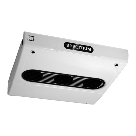
Page 152: Figure 80: Spectrum Evaporator-Front View
Remote Evaporator Unit Description AJA984 Figure 80: Spectrum Evaporator-Front View AJA985 Figure 81: Spectrum Evaporator-Back View... -
Page 153: Unit Operation
Remote Evaporator Unit Description Unit Features The Spectrum multi-temperature refrigeration system provides heavy duty temperature control • Direct Expansion Evaporator Coil for multiple compartment trucks. The system provides direct expansion cooling in all cargo • 12 Vdc Fan Motor compartments. •... - Page 154 Remote Evaporator Unit Description...
-
Page 155: Remote Evaporator Refrigeration Service Operations
Remote Evaporator Refrigeration Service Operations NOTE: It is generally good practice to replace 8. Test the unit to see that the expansion valve is the filter drier whenever the high side is opened properly installed. or when the low side is opened for an extended period of time. -
Page 156: Solenoid Valves
Remote Evaporator Refrigeration Service Operations Solenoid Valves NOTE: Valves that have nylon seats must be disassembled before soldering. Removal 1. Pump down the low side and equalize the pressure to slightly positive. AEA648 2. Remove the access panels. 3. Remove the coil and disassemble the valve. Valve 4. -
Page 157: Remote Evaporator Structural Maintenance
Remote Evaporator Structural Maintenance Unit Inspection Inspect the unit during the unit pretrip inspection and scheduled maintenance inspections for loose or broken wires or hardware, chaffed wires, compressor oil leaks, or other physical damage which might affect unit performance and require repair or replacement of parts. - Page 158 Remote Evaporator Structural Maintenance...
-
Page 159: Remote Evaporator System Diagnosis
Remote Evaporator System Diagnosis Condition Possible Cause Remedy Load temperature too high Refrigerant shortage Repair leak and recharge Setpoint too high Adjust setpoint Expansion valve plugged Clean or replace Partial obstruction in low side of Locate obstruction and repair refrigeration system Iced or dirty evaporator coil Defrost or clean evaporator coil Expansion valve open too much... - Page 160 Remote Evaporator System Diagnosis...
-
Page 161: Index
Index AC components 71 ELC (extended life coolant) 82 accumulator 119 electric fuel pump 87 after start inspection 53 electric operation 52 air switch, specifications 19 electric standby diagnosis 141 air switches 66 electric standby power receptacle 47 alarm codes 71 electric standby, specifications 21 alternator 55 electrical components, specifications 21... - Page 162 (PV) 123 defrost control 26 field test procedure 72 fuel saver 26 radiator coil 118, 133 in-cab conroller 71 RD-MT 30 25 in-cab controller 46 RD-MT 50 25 multi-temp control box 45 receiver tank 120 thermometer 26 receiver tank pressure cutout switch 119...
-
Page 163: Wiring And Schematic Diagrams Index
MD/RD-MT Model 30 w/In-Cab Schematic Diagram 165-166 1E07389 MD/RD-MT Model 30 w/In-Cab Wiring Diagram 167-169 1E07390 MD/RD-MT Model 30 w/In-Cab & CYCLE-SENTRY Schematic Diagram 170-171 1E07391 MD/RD-MT Model 30 w/In-Cab & CYCLE-SENTRY Wiring Diagram 172-174 1E07778 MD/RD-MT Model 30 CYCLE-SENTRY Wiring Diagram... - Page 164 Wiring and Schematic Diagrams Index...
- Page 165 MD/RD-MT Model 30 w/In-Cab Schematic Diagram—Page 1 of 2...
- Page 166 MD/RD-MT Model 30 w/In-Cab Schematic Diagram—Page 2 of 2...
- Page 167 MD/RD-MT Model 30 w/In-Cab Wiring Diagram—Page 1 of 3...
- Page 168 MD/RD-MT Model 30 w/In-Cab Wiring Diagram—Page 2 of 3...
- Page 169 MD/RD-MT Model 30 w/In-Cab Wiring Diagram—Page 3 of 3...
- Page 170 MD/RD-MT Model 30 w/In-Cab & CYCLE-SENTRY Schematic Diagram—Page 1 of 2...
- Page 171 MD/RD-MT Model 30 w/In-Cab & CYCLE-SENTRY Schematic Diagram—Page 2 of 2...
- Page 172 MD/RD-MT Model 30 w/In-Cab & CYCLE-SENTRY Wiring Diagram—Page 1 of 3...
- Page 173 MD/RD-MT Model 30 w/In-Cab & CYCLE-SENTRY Wiring Diagram—Page 2 of 3...
- Page 174 MD/RD-MT Model 30 w/In-Cab & CYCLE-SENTRY Wiring Diagram—Page 3 of 3...
- Page 175 MD/RD-MT Model 30 CYCLE-SENTRY Wiring Diagram—Page 1 of 3...
- Page 176 MD/RD-MT Model 30 CYCLE-SENTRY Wiring Diagram—Page 2 of 3...
- Page 177 MD/RD-MT Model 30 CYCLE-SENTRY Wiring Diagram—Page 3 of 3...
- Page 178 MD/RD-MT Model 50 w/In-Cab Schematic Diagram—Page 1 of 2...
- Page 179 MD/RD-MT Model 50 w/In-Cab Schematic Diagram—Page 2 of 2...
- Page 180 MD/RD-MT Model 50 w/In-Cab Wiring Diagram—Page 1 of 3...
- Page 181 MD/RD-MT Model 50 w/In-Cab Wiring Diagram—Page 2 of 3...
- Page 182 MD/RD-MT Model 50 w/In-Cab Wiring Diagram—Page 3 of 3...
- Page 183 MD/RD-MT Model 50 w/In-Cab & CYCLE-SENTRY Schematic Diagram—Page 1 of 2...
- Page 184 MD/RD-MT Model 50 w/In-Cab & CYCLE-SENTRY Schematic Diagram—Page 2 of 2...
- Page 185 MD/RD-MT Model 50 w/In-Cab & CYCLE-SENTRY Wiring Diagram—Page 1 of 3...
- Page 186 MD/RD-MT Model 50 w/In-Cab & CYCLE-SENTRY Wiring Diagram—Page 2 of 3...
- Page 187 MD/RD-MT Model 50 w/In-Cab & CYCLE-SENTRY Wiring Diagram—Page 3 of 3...
- Page 188 MD/RD-MT Model 50 CYCLE-SENTRY Wiring Diagram—Page 1 of 3...
- Page 189 MD/RD-MT Model 50 CYCLE-SENTRY Wiring Diagram—Page 2 of 3...
- Page 190 MD/RD-MT Model 50 CYCLE-SENTRY Wiring Diagram—Page 3 of 3...
Need help?
Do you have a question about the RD-MT and is the answer not in the manual?
Questions and answers