Terex Series AL4000 Operation & Service Manual
Light tower
Hide thumbs
Also See for Series AL4000:
- Operator's manual (36 pages) ,
- Operation & service manual (73 pages) ,
- Service manual (88 pages)

Related Manuals for Terex Series AL4000


Summary of Contents for Terex Series AL4000
- Page 1 Index SERIES AL4000 LIGHT TOWER OPERATION & SERVICE MANUAL After Serial Number: 0302-77560 PO Box 3147 • Rock Hill, SC 29732 USA • Phone 803-324-3011 Toll Free 800-433-3026 Parts Department Fax 800-633-5534...
- Page 2 Index OPERATOR’S MANUAL...
- Page 3 Index SAFETY ALERT SYMBOLS MEANS: ATTENTION! BE ALERT! YOUR SAFETY IS INVOLVED THIS SAFETY SYMBOL IS USED FOR IMPORTANT SAFETY MESSAGES. WHEN YOU SEE THIS SYMBOL, FOLLOW THE SAFETY MESSAGE TO AVOID PERSONAL INJURY OR PROPERTY DAMAGE. UNDERSTANDING SIGNAL WORDS A signal word - DANGER, WARNING or CAUTION is used with the safety alert symbol.
- Page 4 Index GENERAL SAFETY DO NOT OPERATE THE AL4000 LIGHT TOWER WITHOUT READ- ING THIS OPERATOR’S MANUAL. SAFETY ALERT SYMBOL Stop and take time to read ALL Safety alert messages. Follow the safety messages to avoid personal injury or property damage. ACCIDENT PREVENTION Use protective clothing and safety equip- ment.
- Page 5 Index GENERAL SAFETY FUELING ALWAYS handle fuel with care. It is highly flammable. ALWAYS stop engine before refueling. Fill fuel tank outdoors. Be sure the fuel supply has a positive shut- off valve DO NOT replace fuel lines with materials different from those supplied as original equipment.
- Page 6 Index GENERAL SAFETY Guard Against Electrical Shock Equipment produces high voltage electricity (up to 480 volts) that can produce a fatal shock to a person who accidentally places their self in the electrical circuit. Use every precaution to avoid contact with the high voltage electrical circuit.
- Page 7 Index Guard Against Battery Hazards Lead acid batteries can be dangerous. The sulfuric acid in the battery can cause severe skin and eye burns. The hydrogen gas emitted during charging can explode if an arc or flame is present near the battery. Use precautions to prevent acid burns or explosive conditions.
- Page 8 Do not work on this equipment when mentally or physically fatigued. Do not work on this equipment when under the influence of performance impairing drugs or alcohol. If this manual becomes lost, order a new one from TEREX-Amida so future operation and maintenance personnel may read these instructions.
- Page 9 Index CHECK OUT ON RECEIPT OF DELIVERY: The tower will be serviced, tested and ready for operation when received except for export units and skid mount units which are knocked down for shipping (export units are also shipped with dry batteries). Amida recommends the following checks: INSURE THERE IS NO FREIGHT HANDLING DAMAGE which should be charged against the carrier.
- Page 10 Index LIGHT TOWER MODEL CODING SYSTEM IMPORTANT WHEN REQUESTING TECHNICAL HELP AND ORDERING REPLACEMENT PARTS THE MODEL AND SERIAL NUMBER ARE NECESSARY. REFER TO THE AMIDA SERIAL NUMBER TAG ON THE UNIT FOR CORRECT MODEL NUMBER AND SERIAL NUMBER. MODEL NUMBER IDENTIFICATION Samp1e: Light Tower Product Line 080 D...
- Page 11 Index RECOMMENDED ENGINE OIL & FUEL KUBOTA D905 DIESEL ENGINE (STANDARD) Engine oil should be MIL-L-2104B/MIL-L-2104C or have properties of API designation of CC/SF or CD/SF. Change the type of engine oil according to the ambient operating temperature: Above 86°F SAE 30 32°F to 77°F SAE20...
- Page 12 Index MODEL AL4000 OPERATING INSTRUCTIONS READ ALL DIRECTIONS IN MANUAL CAREFULLY BEFORE OPERATING EQUIPMENT DO NOT RAISE TOWER IN THE VICINITY OF OVERHEAD POWER LINES! O P E R A T I N G I N S T R U C T I O N S MOVE LIGHT TOWER TO DESIRED LOCATION KEEPING THE FOLLOWING IN MIND: The light tower should not be placed where those working under the light are either: 1) Forced to look into the light regularly.
- Page 13 Index INSTALL THE FLOODLIGHTS ON THE CROSSBEAM Remove the light fixtures from the tower by removing detent pin and rotating the clamp to free the lights. Install them on the cross arm studs with the lens facing the ground. The cord on the fixture should be on the side closest to the trailer so the cord entry is beneath the fixture when the tower is raised ( this reduces moisture problems and ensures the water weep hole in the fixture is down).
- Page 14 Index START THE ENGINE / GENERATOR SET Ensure the circuit breakers are turned “OFF”. This prevents the engine from starting under load and prevents electrical equipment from being subjected to improper voltage and frequency. B. Check the oil, fuel, and coolant (if liquid cooled) levels. If the fuel tank is empty, it may be necessary to bleed the fuel line after filling the tank (see engine instruction book for procedure).
- Page 15 Index Operating Procedures (cont’d) E. Rotate the tower so that the groove in the galvanized ring at the pivot is pointing to the rear of the trailer to enable the tower to be lowered into the travel position. Pull the vertical locking-pin at the base of the pivot post (the kick-out spring should provide sufficient pressure to start the tower pivoting over).
- Page 16 When used properly, the wire ropes should give years of trouble-free service, depending on how often the masts are raised and lowered. The rule of thumb at TEREX-Amida is that if the tower is raised and lowered an average of once per day, that the cables should be replaced every two years of service.
- Page 17 Cable Replacement Diagram 6" Round Tube 2" Section Cable 2 Point B 3" Section 4" Section "Hat" Section Cable 1 Point B Cable 2 (190570) Point A Cable 1 (192904) Point A Winch Tower Base Created: Revised: Document: 9-5-97 Terex Light Construction...
- Page 18 Index PARTS MANUAL...
- Page 19 174160, Battery Hold-Down 182330, Battery Hold-Down Rod 124410, Trailer Frame 124470, Tongue 114480, Outrigger 834219, Handle (Hammerblow) 834204, Handle (Fulton) 841430, Jack 840222, Jack Snap Ring 840221, Jack Bracket 110870, Safety Chain Created: Revised: 6-25-02 Document: 9-5-97 Terex Light Construction...
- Page 20 Model: Page: AL4000 LIGHT TOWER Title: Fuel Tank 742240-1, Tank Cap (4) 990200, Lock Nut 742220, Fuel Tank 188630, Fuel Tank Pan (8) 990210, Flat Washer (4) 994650, 1/2"-13NC x 10" Bolt Created: Revised: 6-25-02 Document: 9-5-97 Terex Light Construction...
- Page 21 841060, Tire & Wheel Mounted 840376, Lug Nut (3) 840395, Axle Spring Nut 840392, Axle Rear Hanger (3) 840394, Axle Spring Bolt 841051, Axle Front Hanger 841473, Axle Shackle (2) 834246, Spring Eye Bushing 834211, Leaf Spring Created: Revised: Document: 9-5-97 Terex Light Construction...
- Page 22 124420, Ground Rod Storage Tube 188530, Cabinet, Front Radiator Overflow Bottle Bracket (2) 189390 Elec. Box Mtg. Bracket 176370 Literature (2) 930950 Rack Weatherstrip 124430, Cabinet, Rear (2) 123490 Fender 188580, Cabinet, Curbside (10) 791840 Rubber Bumper Created: Revised: Document: 9-5-97 Terex Light Construction...
- Page 23 123680, Pin 188550, Cabinet Top (4) 796436, Gas Shock 794940, Plastic Plug (4) 796432 Door Shock Bracket (2) 796610 Hinge (2) 790040 Hasp Kit 111368 Ground Rod (2) 188560 (2) 790940, Handle Cabinet Door Created: Revised: Document: 9-5-97 Terex Light Construction...
- Page 24 Index Model: Page: AL4000 LIGHT TOWER Title: Cab. Decal 851640 853296 853296 Curb Side Road Side 853301 853301 853312 853312 852410 851860 853730 853291 850090 Front Rear (2) 841710 www.terex.com 853291 850135 853301 Created: Revised: Document: 9-5-97 Terex Light Construction...
- Page 25 Index Model: Page: AL4000 LIGHT TOWER Title: Tower Assy. 113080, Coil Cord Sleeve See 2" Section See 3" Section See 4" Section See 6" Round Tube Created: Revised: Document: 9-5-97 Terex Light Construction...
- Page 26 990660, Roll Pin 113362, Lock Pin 177810 790510, 1/16" Cable Shim (3) 790520, Cable Sleeve 990760, "R" Pin 120640, Pin 980340 Screw 990650 Cotter Pin 790710 Spring See 6" Round Tube Created: Revised: 6-25-02 Document: 9-5-97 2-3-03 Terex Light Construction...
- Page 27 3/8 x 2 992765 Clevis Pin (2) 995790 1/2 x 2 Clevis Pin 1/4 x 2 183285, 3/8" Shim 183286, 5/16" Shim 177830, 1/4" Shim 183828, 3/16" Shim Orientation of Shims Inside Tube Created: Revised: Document: 9-5-97 Terex Light Construction...
- Page 28 (2) 995790 Clevis Pin 1/4 x 2 124550 3" Tower Section 109065 Cable Kit Orientation of Shims Inside Tube 185290, 3/8" Shim 996230 3/8" Screw 990470, Lock Washer (3) 177820, 5/16" Shim Created: Revised: 6-25-02 Document: 9-5-97 Terex Light Construction...
- Page 29 Index Model: Page: AL4000 LIGHT TOWER Title: 2" Section 124560, 2" Tower Section 109070, Cable Kit 990470, Lock Washer 996230, 3/8" Bolt Created: Revised: 6-25-02 Document: 9-5-97 Terex Light Construction...
- Page 30 Index Model: Page: AL4000 LIGHT TOWER Title: Tower Crossarm / Fixture (4) See Fixture Assembly 113040, Cross Arm Cross Arm Mounting Plate (4) 123080, Fixture Mounting Wing Nut Created: Revised: Document: 9-5-97 Terex Light Construction...
- Page 31 994920 Cotter Pin 3/32 x 3/4 990620 990650 Lock Nut Cotter Pin 1/8 x 1 124530 6" Round Tube 992765 Clevis Pin 1/2 x 2 188760 995790 Sheave Clevis Pin 1/4 x 2 Created: Revised: Document: 9-5-97 Terex Light Construction...
- Page 32 Index Model: Page: AL4000 LIGHT TOWER Title: Tower w/ Base Assy. 113040, Crossarm 116220, Tower Assy. w/ Cables 116170, Tower Base 740055, Winch 1500# 124480, Winch Handle Created: Revised: Document: 9-5-97 Terex Light Construction...
- Page 33 Tower Base Assy. 124490, Tower Base 184620, Base Winch Mount 740055, Manual Winch 193750, Kick-Out Spring 109486, Winch-Loc Kit 124480, Winch Handle 186360, Bumper Pad 184510, Spool Sheave 113362, Pin Slide Lock Created: Revised: 6-25-02 Document: 9-5-97 2-3-03 Terex Light Construction...
- Page 34 AL4000 LIGHT TOWER Title: Tower Base Assy. 990080 WASHER, FLAT WASHER, 124858 996051 SCREW, 1/2-13 BY 7-1/2" LONG *NOT INCLUDED WITH 109485 124855 124856 990200 109485 WINCH SAFETY-LOC SYSTEM (INCLUDES NEW WINCH) Created: Revised: Document: 5/20/02 6-25-02 Terex Light Construction...
- Page 35 109350 (Leroy Somer) 866030, Soleniod 866040, Gasket 836857, Diode Generator 630930 Leroy Somer (Shown) 866050, Oil Filter 866080, V-Belt 866110, Radiator 865223, Electric Fuel Pump Mounted to Trailer Frame 740620, In-line Fuel Filter Created: Revised: 6-25-02 Document: 9-5-97 Terex Light Construction...
- Page 36 Index Model: Page: AL4000 LIGHT TOWER Title: Genset, Kub-D905/L-S 6KW 866090, Alternator 839190, Low Oil Press. Sensor 836835, End-Kit With Bearing 836830, O-Ring 866100, Starter 836828, Rear Bearing Created: Revised: Document: 9-5-97 Terex Light Construction...
- Page 37 Index Model: Page: AL4000 LIGHT TOWER Title: Generator Mounting Bar 630930, Generator 6kW (Leroy Somer) (2) 990200 Lock Nut 189335, Generator Mounting Bar (4) 990210, Flat Washer (2) 990820, Bolt Created: Revised: 6-25-02 Document: 9-5-97 Terex Light Construction...
- Page 38 Page: AL4000 LIGHT TOWER Title: Right Side Radiator/Engine Mtg. Bracket Engine Block (4) R980175, Flat Washer (4) 994830, Lockwasher (4) 995110, Screw Radiator Mounting Bracket 189290, Engine Mounting Bracket 740920, Vibration Mount Assy. Created: Revised: Document: 9-5-97 Terex Light Construction...
- Page 39 Index Model: Page: AL4000 LIGHT TOWER Title: Fuel Filter 839200, Kubota Fuel Filter Created: Revised: Document: 6-25-02 9-5-97 Terex Light Construction...
- Page 40 Index Model: Page: AL4000 LIGHT TOWER Title: Radiator/Overflow Tank 866120, Radiator Cap 865307, Overflow Tank Kit 866110, Radiator Created: Revised: 6-25-02 Document: 9-5-97 Terex Light Construction...
- Page 41 663870, Connector 3P Female 660287, Coil Cord 663890, Female Cord Set 680080, Strain Relief 121620, Box W/ Mount Bar 852800, Decal 680190, Box Cover W/ Gasket 112555, Junction Box / Coil Cord Kit Created: Revised: Document: 6-25-02 9-5-97 Terex Light Construction...
- Page 42 Index Page: STANDARD LIGHT TOWER MH/ MV/ HPS LIGHT FIXTURE...
- Page 43 Index...
- Page 44 121572, Combo Hitch Ring 16" Long 940000, Kit, Combo Hitch 213770, Ring Hitch 2-1/2" I.D. 124450, Hitch, 24" Height 221580, Hitch, Adj. Height 211410, 2-1/2" I.D.Ring Hitch for Adj Height 841200, Hitch, Pintle Ring, 3" I.D. Created: Revised: Document: 2-2-99 Terex Light Construction...
- Page 45 Index 160992, Electric Winch, 12V 663780, Switch 160993, Solenoid 113583, Switch / Solenoid Assembly 6-25-02...
- Page 46 Index 663520, License Tag Light w/ Bracket 663510, Stop, Tail & Turn Light...
- Page 47 Index...
- Page 48 Index...
- Page 49 Index...
- Page 50 Index...
- Page 51 Index...
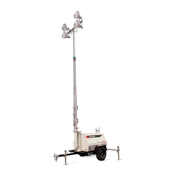
- Page 52 Light Tower – General Specifications And Routine Maintenance TEREX Amida model AL4000 series light tower provides mobile; trailer mounted floodlighting for nighttime maintenance, construction, mining, and emergency work. It consists of a trailer with a diesel powered 6 kW 60Hz (50 Hz units available) generator, and a 30 foot cable actuated tower with four (4) 1000 watt floodlight fixtures.
- Page 53 Index MANUAL WINCH Maintain a light film of automotive-type grease on the pinion, drum gear, and the O.D. of the drum bearing at all times. Keep the ratchet pawl pivot, pinion shaft bushings, and pinion threads lubricated with automotive engine oil at all times. Before each use, check the brake friction discs for wear.
- Page 54 Index MISCELLANEOUS SPECIFICATIONS The Amida AL4000 light tower is built to NEC standards. FASTENER TORQUE SPECIFICATIONS All fasteners should be torqued to the following specifications in lb-ft (lb-in): FASTENER STAINLESS STAINLESS SAE GRADE SAE GRADE SAE GRADE SAE GRADE SIZE STEEL* STEEL* 5 PLATED...
- Page 55 Index WIND LOADING CHARACTERISTICS All wind load calculations were performed with the tongue at 12 o’clock, the wind coming from the direction shown with the lights flat-facing into the wind. WIND DIRECTION SPEED FROM 12 O’CLOCK 78 MPH FROM 1 & 11 O’CLOCK 83.8 MPH FROM 2 &...
- Page 56 Index BROKEN CABLE REPLACEMENT PROCEDURE 1. PREPARATION Collapse tower to where mast is retracted, then pivot tower to horizontal position. Remove the tower from the trailer and place it on a work surface such as two saw horses. 2. REMOVING TOP CABLE AND TOP MAST SECTION Tie middle section and large section together by wrapping band, cable, chain, or rope around the sheave brackets on these two sections.
- Page 57 Index Pass the free end of the cable through the sheave slot between the large and middle sections and out of the top of the tower. Pull the cable and the middle section completely out of the large section altogether. Be sure to keep the cable tight, if slack accumulates it is most difficult to remove. If the fish wire doesn’t work, it is necessary to remove the square mast section from the round mast section.
- Page 58 Index LIGHT FIXTURE TROUBLESHOOTING Do not open fixtures while light circuit breaker is “ON”. Allow lamp to cool before touching. **TAKE EXTRA PRECAUTIONS WHEN TROUBLESHOOTING ELECTRICAL PROBLEMS** A. Only use a voltmeter with two well-insulated pin probes rated for 600 volts. B.
- Page 59 Index LIGHT FIXTURE TROUBLESHOOTING (cont’d) SYMPTOM CAUSES CORRECTIVE ACTION LAMP STARTS Defective Lamp Lamp may glow for extended period of time. Replace after SLOWLY (ARC checking voltage and ballast. DOES NOT STRIKE WHEN SWITCH IS FIRST TURNED ON) CIRCUIT Short circuit Checking wiring against diagram.
- Page 60 Index LIGHT FIXTURE TROUBLESHOOTING (cont’d) SYMPTOM CAUSES CORRECTIVE ACTIONS SHORT LAMP Lamp damaged Check for outer bulb cracks. If air enters outer bulb, arc tube LIFE may continue to burn for 100 hours before failure. Check for bulb cracks where glass meets the base due to tightening lamp too firmly in socket.
- Page 61 Index TRACEABLE NUMBERED WIRING SYSTEM (Using plug in ballasts to troubleshoot) When troubleshooting the preceeding problems, minimize down time by following the traceable numbered wiring system, always follow these steps: STEP1: Insure all ballasts, which are numbered, are plugged into lead wires with corresponding numbers.
- Page 62 Index Rear Bearing Inspection Requirements Leroy-Somer 6 & 8 kw Generators The rear bearing on all 6 & 8 kW generators should be inspected every two (2) years or 2000 hours, whichever occurs first. The bearing should be replaced at three (3) years or 3000 hours. Careful attention to this inspection proeedure will prevent total generator failure resulting from bearing or bearing carrier deterioration.
- Page 63 After inspecting the defective part(s), and it is determined that warranty is due, we will then, at the discretion of TEREX LIGHT CONSTRUCTION , credit the applicants account or send replacement parts.
- Page 64 TEREX Light Construction, shall be limited to the repair of replacement of goods returned, transportation prepaid to TEREX Light Construction. TEREX Light Construction shall in no event be liable for incidental or consequential damages.
Need help?
Do you have a question about the Series AL4000 and is the answer not in the manual?
Questions and answers