Table of Contents
Advertisement
Quick Links
Power Drives
Manual
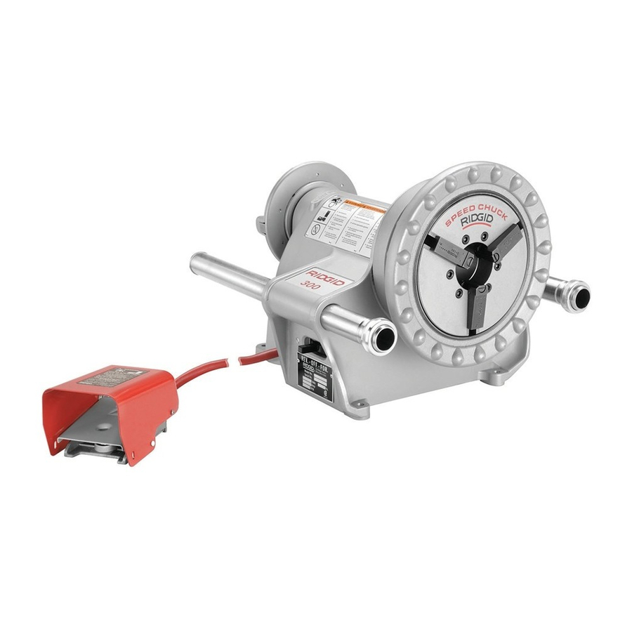
300 Power Drive
WARNING!
Read this Operator's Manual
carefully before using this
tool. Failure to understand
and follow the contents of
this manual may result in
electrical shock, fire and/or
serious personal injury.
•
Français – 19
•
Castellano – pág. 39
GlobalTestSupply
www.
.com
Find Quality Products Online at:
sales@GlobalTestSupply.com
Advertisement
Table of Contents

Related Manuals for RIDGID 300 Power Drive


Summary of Contents for RIDGID 300 Power Drive
- Page 1 Power Drives Manual 300 Power Drive WARNING! Read this Operator’s Manual carefully before using this tool. Failure to understand and follow the contents of this manual may result in electrical shock, fire and/or serious personal injury. • Français – 19 •...
-
Page 2: Table Of Contents
300 Power Drive Table of Contents Recording Form for Machine Serial Number......................1 General Safety Information Work Area Safety................................2 Electrical Safety ................................2 Personal Safety ................................2 Tool Use and Care..............................3 Service..................................3 Specific Safety Information Foot Switch Safety..............................3 Machine Safety ................................3 Description and Specifications, Standard Equipment Description..................................4... -
Page 3: Recording Form For Machine Serial Number
Power Drives Power Drive Model 300 Complete pictured above including Stand, Threading Carriage, Tool Tray and Oiler. 300 Power Drive Record Serial Number below and retain product serial number which is located on nameplate. Serial GlobalTestSupply www. .com Find Quality Products Online at:... -
Page 4: General Safety Information
300 Power Drive • Do not abuse cord. Never use the cord to carry the General Safety Information tools or pull the plug from an outlet. Keep cord away from heat, oil, sharp edges or moving parts. WARNING Replace damaged cords immediately. Damaged Read all safety warnings and all instructions. -
Page 5: Tool Use And Care
• Power Drive is made to thread and cut pipe or or storing the tool. Such preventive safety mea- bolt and to power RIDGID roll grooving equip- sures reduce the risk of starting the tool accidentally. ment. Follow instructions on proper use of this machine. -
Page 6: Description And Specifications, Standard Equipment
NOTE! Contact a RIDGID distributor or consult the Figure 2 – No. 300 Power Drive and No. 1206 Stand RIDGID catalog for specifications on roll groov- ing equipment. -
Page 7: Machine Assembly
Power Drive to a stable stand or bench may result in tipping and serious injury. The following proce- dures should be followed: Figure 3 – 300 Power Drive Mounted on No. 1206 Stand with 418 Oiler Mounting on No. 1206 Stand Mounting 311A Carriage and Tools 1. -
Page 8: Machine Inspection
Support Bar (2) tion of the machine. If any of these conditions are pre- Figure 4 – No. 300 Power Drive with 311A Carriage, 360 sent, do not use the Power Drive until any problem Cutter, 341 Reamer and Die Head has been repaired. -
Page 9: Machine And Work Area Set-Up
If such con- ditions are present, have the power drive serviced. 6. If necessary, fill the 418 Oiler with RIDGID Thread Cutting Oil. Position the oiler under the front of the • Flip the directional switch to REV (Reverse). Press Power Drive (Figure 3). -
Page 10: Operating Instructions Using Hand Tools
300 Power Drive Operating Instructions Cutting Pipe with Hand Cutter For Using Hand Tools 1. Position the pipe cutter on the workpiece with the cutter wheels facing up (see “Accessories” section WARNING for pipe cutters recommended for use with this Power Drive). -
Page 11: Reaming Pipe With Hand Reamer
Straight Hand Reamer Support Figure 7 – Pushing Hand Threader onto Pipe to Engage Dies 4. Apply RIDGID Thread Cutting Oil to the end of the pipe. Support Bar Hand Grip 5. Assume the correct operating posture. Check to ensure directional switch is in the FOR (Forward) position. -
Page 12: Removing Pipe From Power Drive
300 Power Drive 12. Reverse the ratchet knob. The arrow on the knob should point down. 13. Lower the threader handle below the height of the left support bar. Handle Hand 14. Slide the left support bar back to its fully extended Threader position in front of the Power Drive. -
Page 13: Installing Pipe In Power Drive
300 Power Drive Operating Instructions 2. Move pipe cutter down onto pipe and move carriage with carriage lever to line up cutter wheel with mark for Carriage-Mounted on pipe. Power Drive Tools 3. Tighten cutter feedscrew handle while keeping the WARNING cutter wheel aligned with the mark. -
Page 14: Threading Pipe With Quick-Opening Or Self-Opening Die Head
Latch Wheel throwout lever down until the release trigger cocks. 6. Apply RIDGID Thread Cutting Oil to end of the pipe. 7. Assume the correct operating posture. 8. Check directional switch to insure it is in the FOR (Forward) position. Depress and hold the foot switch down with the left foot. -
Page 15: Installing Dies In Quick-Opening Die Head (R.h. & L.h.)
300 Power Drive ″), ( ″ – ″), ( ″ – ″) and (1″ – 2″). The size ranges: ( ″ pipe dies are not available for left hand die head. Bolt Die Head threading requires a separate set of dies for each bolt size. -
Page 16: Installing Dies In Self-Opening Die Head (R.h. Only)
300 Power Drive Installing Dies in No. 815A Self-Opening Size Bar Die Head (Right Hand Only) Roll Pin NOTE! The No. 815 Self-Opening Die Head (Figure 13) for right hand threads requires four sets of Index Line ″ through 2″. -
Page 17: Accessories
Pipe No. 2 and 3 Ratchet Reamers Starting to Cut Thread Completed Thread Contact a RIDGID distributor or consult the Ridge cat- A - Full Width Die Thread alog for specifications and catalog numbers. Thin Ring 311A Carriage and Tools as Accessories... -
Page 18: Jaw Insert Replacement
Figure 15 – Replacing Jaw Inserts performed by qualified repair personnel. Power Drive should be taken to a RIDGID Independent Authorized 1. Place screwdriver in insert slot and turn 90 degrees Service Center or returned to the factory. All repairs in either direction. -
Page 19: Wiring Diagram
300 Power Drive Wiring Diagram (115/230V) 1. Brush and Armature Leads may be solid colors or white with a colored stripe. 2. Wire Colors in parenthesis represent Euro - pean color code. European cord is the same except for plug. - Page 20 300 Power Drive Wiring Schematic (230V) with Line Filter OTE! Colors in parenthesis represent European color code. FOR/REV Switch 230V AC Brown Neutral Blue Blue Green/Yellow Ground (Earth) Motor Yellow White Black Blue (Green/Yellow) Foot Switch Brown Black Filter GlobalTestSupply www.
- Page 21 No other express warranty applies This FULL LIFETIME WARRANTY is the sole and exclusive warranty for RIDGID ® products. No employee, agent, dealer, or other person is authorized to alter this warranty or make any other war- ranty on behalf of the RIDGE TOOL COMPANY.
Need help?
Do you have a question about the 300 Power Drive and is the answer not in the manual?
Questions and answers