Table of Contents
Advertisement
Any Time, Anywhere
Unication is committed to Provide You the Best Solution
Voice Pager Supports
G 4
P25 Radio
Systems Now!
Voice Pager Specially Designed for Public Safety
ecially Designed for
Advanced Radio Performance
dvanced Radio Performan
Mission Critical Applications
ission Critical Application
Optional GSM Features Available
ional GSM Features Availa
US-G4-FF-20150126-V1
Advertisement
Table of Contents

Related Manuals for unication G4


Summary of Contents for unication G4
- Page 1 Any Time, Anywhere Unication is committed to Provide You the Best Solution Voice Pager Supports P25 Radio Systems Now! Voice Pager Specially Designed for Public Safety ecially Designed for Advanced Radio Performance dvanced Radio Performan Mission Critical Applications ission Critical Application...
-
Page 2: Table Of Contents
I N D E X Part A: G4 Specifications and Features Part B: Pager Overview B1 Pager Appearance B2 LCD Display B3 LED Introduction B4 Icon Introduction Part C: Operation Introduction C1 Initial Use C2 Pager Message Box C3 Function status... -
Page 3: Part A: G4 Specifications And Features
Part A. G4 Specifications and Features G4 Digital Trunking and Analog Voice Pager Specification & Feature A1 Operating Environment Operating Temperature Range -30 to + 60°C Physical Operating Environment ESD (Electrostatic Discharge) contact ± 8KV Air ± 15KV Analog (AM / FM) - Page 4 Part A. G4 Specifications and Features G4 Digital Trunking and Analog Voice Pager Specification & Feature A2 Hardware Specification Blue - Power on / Connected with USB LED Type (monochrome / cable / Charging completed multicolor) : red / green / blue /...
- Page 5 Part A. G4 Specifications and Features G4 Digital Trunking and Analog Voice Pager Specification & Feature A3 Electrical Characteristics SPL (12") : Alert Speech Audio Performance tone loudness at 94 +/- 2 dB SPL Output 12 inches Low band Frequency Stability :...
-
Page 6: Part B: Pager Overview
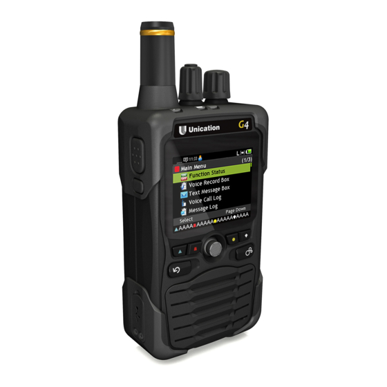
Part B. Pager Overview B1. Pager Appearance Front View Side View Rear View Description LED Indicator Navigation Key Top View Soft Key (K1~K4) Back Key (F2) Home Key (F1) Speaker Microphone Receive Antenna Channel Knob Play Key Power on/off & Volume Knob Accessories Reset Key Belt Clip... -
Page 7: B2 Lcd Display
B3. LCD Introduction Power LED Message LED Power LED: Entity Key Description Power on process Blue USB cable is connected to G4 and charging is completed. Flash Blue Charging Message LED: Entity Key Description Receiving voice call or data call... -
Page 8: B4 Icon Introduction
Part B. Pager Overview B4. Icon Introduction Status Bar Icon Item Icon Description RF Strength RF signal strength. Out of Range Signal is out of range. Message Hint Unread message icon indication. Time Display Time display (24 hour clock). Off Duty Status Off duty status. -
Page 9: Part C: Operation Introduction
You will hear “click” sound and see the word of “Loading” on the display. USB power specification: 5V/1A Power on Standby Screen On the standby screen, G4 displays information on the current receiving mode. User Group Receiving Mode Zone/Channel Main Channel... -
Page 10: C2 Pager Message Box
Part C. Operation Introduction Main Menu In Standby Mode, press the “K1” soft key to enter the Main Menu. Press the “Home” key to go back to Standby Mode. C2. Pager Message Box View and Manage Text Message Records in Message Box. -
Page 11: C3 Function Status
Part C. Operation Introduction C3. Function status Enter Function Status: Use the Navigation key to select Function Status in the Main Menu. Basic Operation: Use the Navigation Key to select features to set. Select Zone: Press the "K1" Key to enter setting screen. Use the Navigation Key to select Zone and then press the “K1”... - Page 12 Connect another Bluetooth Device: Press the “K1” to start searching for Bluetooth devices other than earphone. If only a Bluetooth device is found, the G4 starts pairing to the device. The G4 shows the pairing status on the screen. If there are 2 or more devices, use the Navigation Key to select device and press the “K1”...
-
Page 13: C4 Voice Memo Box
Part C. Operation Introduction C4. Voice Memo Box View and Manage Voice Memo in Voice Memo Box. Enter Voice Record Box: Use the Navigation Key to select the Voice Memo Box in the Main Menu. Record a New Voice Memo: If there is no voice memo, press the “K1”... -
Page 14: C5 All Band Scan
Part C. Operation Introduction C5. All Band Scan Set a range to scan, or view the scanned channel list. Enter Voice Record Box: Use the Navigation Key to select All Band Scan in the Main Menu. Use the Navigation Key to select a feature, and press the “K1”... -
Page 15: C6 Function Setting
Part C. Operation Introduction C6. Function Setting View and manage pager basic function. Enter Function Status: Use the Navigation Key to select Function Setting in the Main Menu. Basic Operation: Use the Navigation Key to select function. Press “K1” Key to start setting. Zone: Please refer C2-1 to get detailed information. - Page 16 Part C. Operation Introduction Backlight Dim Time: Adjust screen backlight dim time. Use the Navigation Key to move. Press the “K1” Key to make highlighted value +5. Press the “K2” Key to make highlighted value +1. Press the “K3” Key to make highlighted value -1. Press the “K4”...
-
Page 17: C7 Information
Part C. Operation Introduction Ring Mode: Select Ring mode. There are 5 modes: Tone: Tone only. Vibrate: Vibrate only. Silent: Mute mode. Vibrate then tone: Vibrate first then tone. Tone and Vibrate: Both. Use the Navigation Key to move. Press the “K1” Key to select. Press the “K4”... -
Page 18: C8 Diagnostic
Part C. Operation Introduction C8. Diagnostic View the radio signal strength. Enter Message Box: Use the Navigation Key to select Message Box in the Main Menu. Read Information: Rpt Name: Name of repeater RSSI(dBm): Radio Signal Strength Indicator. Protocol: Using Protocol of current channel. Frame Error: Received signal error radio. -
Page 19: Part D: Warning And Important Notes
Part D. Warning and Important Notes Notice : The changes or modifications not expressly approved by the party responsible for compliance could void the user’s authority to operate the equipment. Important Note : To comply with the FCC RF exposure compliance requirements, no change to the antenna or the device is permitted.
Need help?
Do you have a question about the G4 and is the answer not in the manual?
Questions and answers