Table of Contents
Advertisement
Quick Links
Advertisement
Table of Contents

Related Manuals for Motorline MC2


Summary of Contents for Motorline MC2
- Page 1 USER / INSTALLER MANUAL v1.0 REV. 04/2015...
-
Page 2: Table Of Contents
00. CONTENT 01. SAFETY INSTRUCTIONS INDEX STANDARDS TO FOLLOW 01. SAFETY INSTRUCTIONS ATTENTION: STANDARDS TO FOLLOW • To ensure the safety of people, it is important that you read all the following instruc- 02. THE CONTROL BOARD tions. • Incorrect installation or incorrect use of the product can cause physical injury and TECHNICAL SPECIFICATIONS material damage. -
Page 3: The Control Board
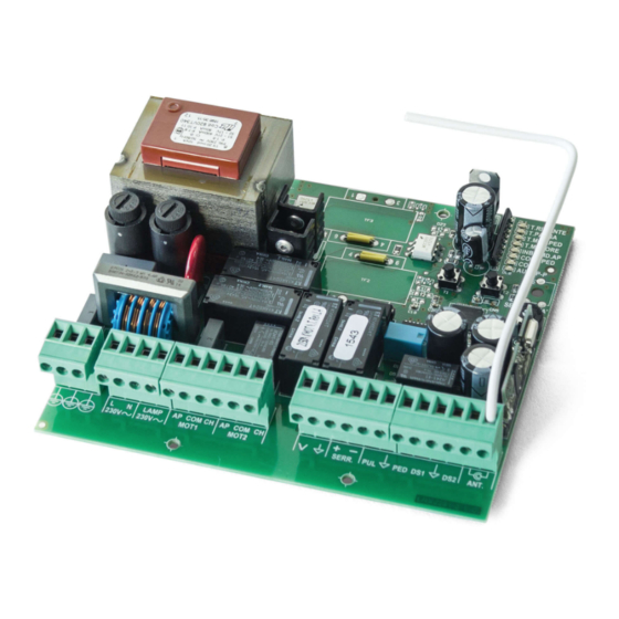
02. THE CONTROL BOARD 02. THE CONTROL BOARD TECHNICAL SPECIFICATIONS TECHNICAL SPECIFICATIONS • CONNECTOR’S DESCRIPTION The MC2 is a central electronic single phase with incorporated radio, for automation of swing gates. 01 • Earth connection • Power supply 230V AC 50-60Hz 02 •... -
Page 4: Programming Pre-Recomendations 3A
02. THE CONTROL BOARD 02. THE CONTROL BOARD PROGRAMMING PRE-RECOMENDATIONS PROGRAMMING PRE-RECOMENDATIONS Before proceeding to the control board configuration, note the following points listed • PROGRAMMING THE CONTROL BOARD - BUTTONS SEL/SET in the table below: SEL button: It makes the selection of the function to change. The se- lection is identified by the flashing of the LED corresponding to the selected function at that time. -
Page 5: Configuration
MAIN MENU MAIN MENU This is the main menu of the control board MC2, which has access to the most impor- closing, it will stop and will restart only when receive new order. tant functions of its operation. The control board is supplied with the active main menu. - Page 6 03. CONFIGURATION 03. CONFIGURATION MAIN MENU MAIN MENU • INB. CMD. AP Program working time of the motor without deceleration (Gate closed): TRANSMITTER INHIBITION DURING THE OPENING AND PAUSE TIME 01. Press the SEL button the times necessary until the LED T.MOT. start to flash. With the function activated, the control board rejects all the remote controls signals 02.
-
Page 7: Extended Menu 1
03. CONFIGURATION 03. CONFIGURATION MAIN MENU MAIN MENU Programming pedestrian working time without deceleration (gates closed): 02. Press the SET button for 1 second. From that moment, the waiting time before pres- 01. Press SEL button as often as necessary until the LED T. MOT. PED. starts flashing. sing SET will be equal to the time that the gate stays open. -
Page 8: Extended Menu 1
03. CONFIGURATION 03. CONFIGURATION EXTENDED MENU 1 EXTENDED MENU 1 • AUT/P-P 03. Press SET button for 1 second PROGRAMMING OF THE REMOTE CONTROL ON DISTANCE 04. The LED CODE PED on indicates that the function is activated and the LED off indi- The function of programming the remote controls on distance, it allows them to be ad- cates that the function is disabled. - Page 9 03. CONFIGURATION 03. CONFIGURATION EXTENDED MENU 1 EXTENDED MENU 2 Activate (LED ON) / deactivate (LED OFF) function: • AUT/P-P | FOLLOW ME 01. Activate the extended menu 1. With the programmed pause time, it is possible to trigger "Follow Me" option. 02.
- Page 10 03. CONFIGURATION 03. CONFIGURATION EXTENDED MENU 2 EXTENDED MENU 2 • INB. CMD. AP. | PUL= opening, PED= closing (LED ON) / PUL=PUL and PED=PED (LED OFF): SOFT START 01. Enter the extended menu 2. With function "Soft Start" enabled, the beginning of each movement, the control board 02.
-
Page 11: Reset Of Control Board
03. CONFIGURATION 04. COMPONENT TEST EXTENDED MENU 3 CAPACITORS CONNECTION SCHEME Motor power programming during the deceleration: To detect which components have problems on an automated system, sometimes it is It is possible to choose up to 6 different levels, relatively the force that the motor per- necessary to conduct tests using a direct connection to a 230V AC power supply. -
Page 12: Troubleshooting
10.B); • Motor opens • Unlock motor and • Gate opened but 1 • Check if there is any All MOTORLINE control boards have LEDs that A) SECURITY SYSTEMS: B) SISTEMAS DE START: but doesn’t move the gate by hand didn’t close again. -
Page 13: Connection Scheme
06. CONNECTION SCHEME CONTROL BOARD CONNECTION COMPONENT Black Blue Brown Brown Blue Black Earth wire Earth wire...
Need help?
Do you have a question about the MC2 and is the answer not in the manual?
Questions and answers