
Related Manuals for Motorline MC1


Summary of Contents for Motorline MC1
- Page 1 USER / INSTALLER MANUAL T.PAUSA T.MOT.PED T.MOT PGM.AUT LAMP/CORT IN.CMD.AP. CODE PED CODE V1.0 REV. 02/2016...
-
Page 2: Table Of Contents
LEDS when used with components that were not sold by the them. • The ELECTROCELOS S.A. informs that, to guarantee greater compatibility and proper 03. INSTALLATION functioning, install only components MOTORLINE. CONDITIONS AND PRE VERIFICATIONS ESSENTIAL INSTALLATION STEPS Mechanism use: •This product was designed and manufactured strictly for the use indicated in this... -
Page 3: The Control Board
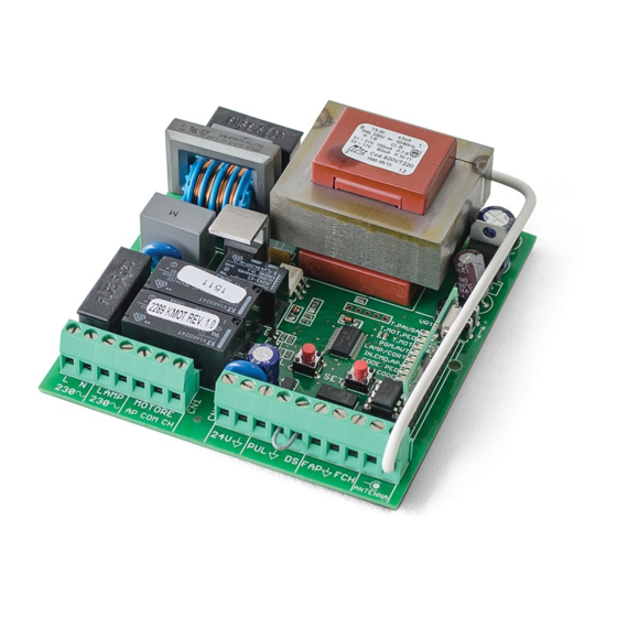
02. THE CONTROL BOARD CONNECTION SCHEME The MC1 is an electronic single phase control board with control system via built-in radio, developed for the automations control for sliding gates or just 1 motor for swing gate. CLOSE OPEN NEUTRAL 110V... -
Page 4: Technical Characteristics
02. THE CONTROL BOARD 02. THE CONTROL BOARD TECHNICAL CHARACTERISTICS TECHNICAL CHARACTERISTICS • PROGRAMMING PRE-RECOMENDATIONS • Power Supply 110V or 230V AC | 50-60Hz | 900W max. (4A) Before proceeding to the control board configuration, note the following points listed 110V/230V AC 500W max. -
Page 5: Sel/Set Buttons 4A
T.PAUSA T.MOT.PED 02. THE CONTROL BOARD 02. THE CONTROL BOARD T.MOT PGM.AUT LAMP/CORT TECHNICAL SPECIFICATIONS TECHNICAL SPECIFICATIONS IN.CMD.AP. CODE PED CODE • SEL/SET BUTTONS • LEDS There are LEDs in the control board to inform the installer about connection status of SEL key the various components. -
Page 6: Installation
03. INSTALLATION 03. INSTALLATION INSTALLATION ESSENTIAL GUIDE CONTROL BOARD INSTALLATION • CONDITIONS AND PRE VERIFICATIONS • Make sure that the motor is properly installed at the gate. • Check if the ambient temperature values are acceptable for the functioning of this control board. -
Page 7: Programming
04. PROGRAMMING 04. PROGRAMMING PRE-INSTALLATION WARNINGS PRE-INSTALLATION WARNINGS • PHOTOCELLS TEST After installing the control board and connecting the wires, you must ensure that all connected components are working properly. To do this, follow these steps: The photocells are a safety device that inform the control board that an object is obstructing the gate's route. -
Page 8: Main Menu 7A
PROGRAMMING TRANSMITTERS This function allows you to program new transmitters to control the automatism. The control board only accepts Dip-Switch code transmitters or Rolling Code MOTORLINE, and has a maximum capacity of 120 codes. When trying to program the 121st code, all the programming LEDs blink a few times simultaneously signaling that the memory is full. - Page 9 04. PROGRAMMING 04. PROGRAMMING MAIN MENU MAIN MENU • INB. CMD. AP | • PGM. AUT. TRANSMITTER INHIBITION DURING THE OPENING AND PAUSE TIME COURSE AUTOMATIC PROGRAMMING With the function activated, the control board rejects all the transmitters and devices With the limit switches already set, the control board allows automatic programming of signals during the opening maneuvers and automatic pause time.
- Page 10 04. PROGRAMMING 04. PROGRAMMING MAIN MENU MAIN MENU • T.MOT AND SLOWDOWN | • T. MOT. PED | PROGRAMMING MOTOR TIME AND RELAXATION (MANUALLY) PROGRAMMING PEDESTRIAN WORKING TIME This function allows you to manually program the distance that the gate opens to Unlike PGM.AUT, this function allows the programming of motor's time and slowdown pedestrian crossing.
-
Page 11: Extended Menu 1
04. PROGRAMMING 04. PROGRAMMING MAIN MENU EXTENDED MENU 1 • T. PAUSA | The control board is supplied with extra functions that can be activated through the PROGRAMMING PAUSE TIME FOR AUTOMATIC CLOSING (MAX 4 MIN) extensed menu 1. This function allows you to set the time that the gate remains open after the end of the opening maneuver. - Page 12 04. PROGRAMMING 04. PROGRAMMING EXTENDED MENU 1 EXTENDED MENU 1 • CODE | • INB. CMD. AP | STEP BY STEP / AUTOMATIC FUNCTIONING PRESENT MAN FUNCTIONING Automatic Mode Functioning (LED CODE ON): When this function is active, the control board only opens / closes the automatism while •...
-
Page 13: Extended Menu 1
04. PROGRAMMING 04. PROGRAMMING EXTENDED MENU 1 EXTENDED MENU 2 • PGM. AUT. | The Extended Menu 2 allows you to program the motor's force/speed during the slowdown FOLLOW ME phase (idling). The control board has 6 different levels of force/speed, represented by With a programmed pause time, you can activate the "Follow Me"... -
Page 14: Other Information
04. PROGRAMMING 05. MAINTENANCE OTHER INFORMATION PARAMETERS TO TAKE CARE • CONTROL BOARD'S RESET Before performing any maintenance, disconnect the control board from the If you need to restore the control unit to the factory settings, follow these steps: electric current. 01 •... -
Page 15: Troubleshooting
06. TROUBLESHOOTING 06. TROUBLESHOOTING COMPONENTS TEST PHOTOCELLS AND TRANSMITTERS TEST • PHOTOCELLS TEST All the tests should be performed by qualified personnel due to the high risk The control board is prepared for the connection of safety devices in accordance with section of accidents that may cause injury or death! 5.1.1.6 of EN 12453. -
Page 16: Instructions For Final Consumers
14.A); • Motor opens • Unlock motor and • Gate opened but 1 • Check if there is any All MOTORLINE control boards have LEDs that A) SECURITY SYSTEMS: B) SISTEMAS DE START: but doesn’t move the gate by hand didn’t close again.
Need help?
Do you have a question about the MC1 and is the answer not in the manual?
Questions and answers
hi, i need the map circuit of mc1.
The circuit map for the Motorline MC1 control board includes the following key components and connections:
- Power Supply: 110V or 230V AC, 50–60Hz
- Motor Output: 110V/230V AC, 50/60Hz, max 750W
- Accessory Output: 24V AC, max 3W
- Light Output: Max 100W (resistive), 50W (induced)
- Limit Switches: Connected to terminals 06 to 08, both normally closed (NC). Activation stops gate movement.
- Photocells: Connected to 2NC. Active only during gate closing; reverse gate on trigger.
- Incorporated Radio Receiver: 433.92 MHz
- Memory Capacity: Up to 120 codes
- Connector Labels:
- OPEN, CLOSE, NEUTRAL, PHASE
- Push Button/Selector Key
- Flashing Light (FLASH)
- Limit Switches (FCH for close, FAP for open)
- Capacitor, Photocells, Motor
The control board supports a single motor for sliding or swing gates and includes built-in radio control.
This answer is automatically generated