Wells WB-2 Supplemental Service Instructions
Waffle bakers with
electronic temperature control
Hide thumbs
Also See for WB-2:
- Owner's manual (24 pages) ,
- Operation manual (13 pages) ,
- Specifications (2 pages)
Table of Contents
Advertisement
Quick Links
0 0
1 1
2 2
W
E L
L S
W
W
E L
E L
L S
L S
IMPORTANT: WELLS BLOOMFIELD PROPRIETARY INFORMATION.
DISSEMINATION OF THIS INFORMATION TO ANYONE OTHER THAN
WELLS AUTHORIZED SERVICE AGENTS IS STRICTLY PROHIBITED.
TECHNICAL CONTENT OF THIS MANUAL IS DESIGNED FOR
USE BY QUALIFIED PROFESSIONAL TECHNICIANS ONLY.
507573
p/n
Rev. (-)
ECN-13404
WELLS BLOOMFIELD, LLC
2 ERIK CIRCLE, P. O. Box 280 Verdi, NV 89439
0 0
1 1
2 2
PRINTED IN UNITED STATES OF AMERICA
telephone: 775-689-5703
fax: 775-689-5976
www.wellsbloomfield.com
SUPPLEMENTAL
SERVICE
INSTRUCTIONS
WAFFLE BAKERS
ELECTRONIC
TEMPERATURE
CONTROL
Model
for
with
WB-1
WB-2
08
S211
0124 cps
212
Advertisement
Table of Contents
Troubleshooting

Related Manuals for Wells WB-2


Summary of Contents for Wells WB-2
- Page 1 WB-2 IMPORTANT: WELLS BLOOMFIELD PROPRIETARY INFORMATION. DISSEMINATION OF THIS INFORMATION TO ANYONE OTHER THAN WELLS AUTHORIZED SERVICE AGENTS IS STRICTLY PROHIBITED. TECHNICAL CONTENT OF THIS MANUAL IS DESIGNED FOR USE BY QUALIFIED PROFESSIONAL TECHNICIANS ONLY. PRINTED IN UNITED STATES OF AMERICA 507573 Rev.
-
Page 2: Precautions And General Information
PRECAUTIONS AND GENERAL INFORMATION This manual is considered to be Wells Bloomfield, LLC proprietary WARNING: information. Dissemination of this information to anyone other than RISK OF Wells Bloomfield authorized service agents is strictly prohibited. PERSONAL INJURY Installation procedures must Technical content of this manual, including any wiring diagrams,... -
Page 3: Specifications
Wiring Diagrams ..............10 INTRODUCTION This manual contains information needed to properly service and repair Wells Waffle Bakers. This manual applies to the following Wells Bloomfield models manufactured after Jan. 1, 2008: WB-1 WB-2 For installation, operation and maintenance instructions, refer to Operation Manual p/n 37055. -
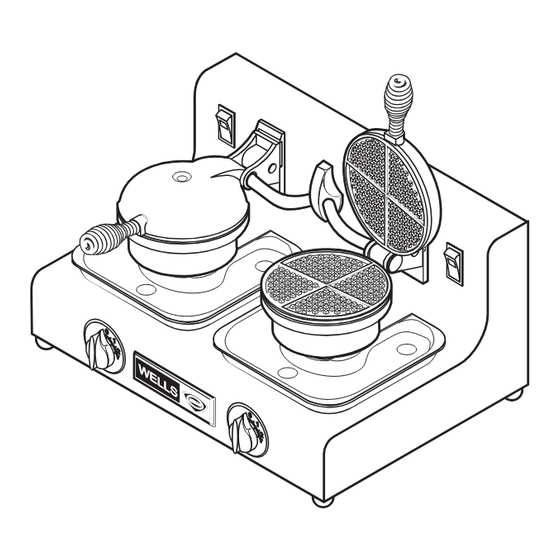
Page 4: Features & Operating Controls
FEATURES & OPERATING CONTROLS UPPER GRID (RAISED POSITION) POWER SWITCH NAME PLATE UPPER GRID (LOWERED POWER POSITION) CORD BACK VIEW HANDLE DRIP TRAY TIMER LOWER GRID TEMPERATURE CONTROL ADJUSTABLE NON-SLIP FEET ITEM COMMENTS TEMPERATURE ADJUSTMENT Dial adjustment of temperature control LOWER GRID ASSEMBLY Lower cooking element;... -
Page 5: Operational Checks
3. Temperature may be adjusted turning the controller dial adjustment (item 6). AMPERAGE VOLTAGE WB-1 WB-2 C. VOLTAGE AND RESISTANCE TEST POINTS TOP GRID ASSEMBLY BOTTOM GRID ASSEMBLY 15.0 TP 4... -
Page 6: Evaluating The Results
OPERATIONAL CHECKS (continued) E. EVALUATING THE RESULTS CAUTION: ELECTRIC SHOCK 1. Presence of 120V in Test #1 or Test #2 (calling for heat but HAZARD element not heating) indicates a damaged heating element. Live electric circuits may 2. Absence of 120V in Test #1 or Test #2 when calling for heat be exposed during these indicates: procedures. -
Page 7: Servicing Instructions
SERVICING INSTRUCTIONS A. TROUBLESHOOTING GUIDE SYMPTOM POSSIBLE CAUSE SUGGESTED REMEDY Unit does not heat Power switch OFF Press switch to ON Unit not plugged in or circuit not Check/reset circuit breaker energized Be sure unit is plugged into an energized outlet Temperature controller not set Adjust controller for desired temperature... - Page 8 CONDUIT, CAST through hinge to P/N 50329 this point Insert small diameter end into hinge SOLID CONDUIT P/N 55552 (90º for WB-1) P/N 55547 (45º for WB-2) PLUG, HINGE PIVOT P/N 50328 HINGE Power wires P/N 50322 Ground wire SCREW 8-32 P/N 51715 (pk 100) Ground wire gets 4“...
- Page 9 SERVICING INSTRUCTIONS (continued) CAUTION: C. BOTTOM GRID ASSEMBLY ELECTRIC SHOCK HAZARD Unplug appliance from electric power before removing any panel or access cover. SERVICE INSTRUCTION - COMPONENT REPLACEMENT WAFFLE BAKER BOTTOM GRID ASSEMBLY ELEMENT, 120V 450W Base and temperature NOTE: Grid assembly P/N 507277 control bracket mount shown inverted...
-
Page 10: Exploded View
HINGE, 50322 E-CLIP 50222 (pk 10) ASSY, HOLE PLUG FITTING, CONDUIT 61064 50329 GASKET, BOTTOM CONDUIT 55547 50338 MOUNTING, CONDUIT ASSY, SHELL WB-2 52101 51551 ASSY, TIMER & KNOB STRAIN RELIEF 50446 51217 BELL TIMER (ONLY) 51549 CONTROLLER, KNOB (ONLY) 50447... - Page 11 EXPLODED VIEW (continued) HANDLE, WIRE 50335 FITTING, CONDUIT 50329 CASTING, UPPER 50327 CLAMPING PLATE UPPER 50431 INSULATION, TOP HOLE PLUG 5/8 DIA ELEMENT 58628 50430 ELEMENT, HEATING 120V 450W (INCL. INSULATORS) 507277 HINGE 50322 GASKET, GRID 50337 PLUG, HINGE GRID, UPPER 50328 58919 SLEEVING, GLASS...
-
Page 12: Wiring Diagrams
WIRING DIAGRAMS MODEL WB-1 SINGLE WAFFLE BAKER 120V SINGLE PHASE POWER UPPER CORD HEATING WHITE ELEMENT 120V 450W BLACK LIGHTED POWER SWITCH TEMPERATURE CONTROL BOARD OUTPUT COMM SENSOR LOWER HEATING ELEMENT 120V 450W WAFFLE BAKER WB-1 VOLTS NOM. AMPS TEMPERATURE SENSOR WHITE 307434 ISSUE (-) - Page 13 WIRING DIAGRAMS (continued) MODEL WB-2 DUAL WAFFLE BAKER 120V SINGLE PHASE UPPER UPPER POWER HEATING HEATING CORD ELEMENT ELEMENT WHITE 120V 450W 120V 450W BLACK LIGHTED LIGHTED POWER POWER SWITCH SWITCH TEMPERATURE TEMPERATURE CONTROL CONTROL BOARD BOARD OUTPUT OUTPUT COMM...
Need help?
Do you have a question about the WB-2 and is the answer not in the manual?
Questions and answers