Table of Contents
Advertisement
Quick Links
INSTRUCTION MANUAL
IMPORTANT: Read carefully. It is essential for the correct and safe use of the
equipment that erectors and operators should be fully conversant with the
information and instructions given in this manual.
1
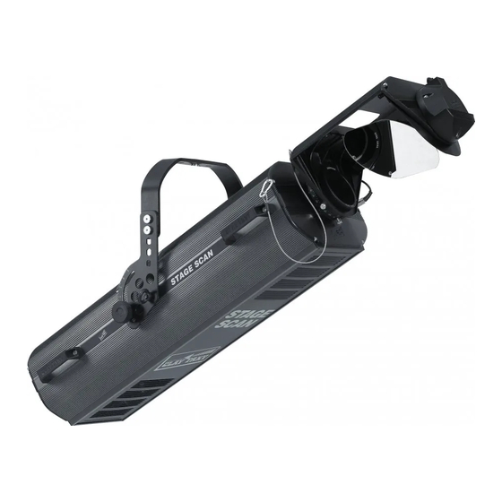
INSTALLING THE PROJECTOR
• Unpacking
Open the box, remove the projector from the packing and place it on a flat hori-
zontal surface. Unpack the standard accessories supplied with the equipment.
Inspect the lamp change label (1) and replace with one of the optional language
versions if necessary.
Make certain that the label is never removed, as it displays important safety
information.
1
• Initial assembly operations
Position the block (2) over the threaded holes on the projector housing, offer the grad-
uated plate (3) and secure with the eyebolt (4), then fit the knob (5) and washer (6).
Align the bracket (7) with the plate (3) so as to give the desired height, insert the
bushing (8), the countersunk washer (9) and the screw (10) in the selected holes and
secure with the Allen key supplied.
The bracket (7) can also be fitted from the underside of the projector by reversing the
position of the graduated plates (3).
Adjust the bracket to the desired angle and secure by tightening the knobs (5).
Fix the safety wire (11) of the effects cover (16) and the lamp access cover
(12) to the graduated plate (3).
Fit the four side handles (13) with the screws (14) provided.
12
7
15 16
11
STAGE SCAN
6 5
2
3
4
13
8
3
5
9
10
14
• Fitting the lamp
Refer to directions for replacement of the lamp given under heading 7 MAINTENANCE.
• Removal of transit bands
Loosen the knob (15) and remove the effects
cover (16) from the projector.
Locate the effects assembly frame and remove
all elastic transit bands (17) from the colour, fil-
ters. Replace the cover and tighten the knob.
• Installing the projector
The projector can be mounted in any position with-
out its operating characteristics being affected.
IMPORTANT: fix the projector in the desired
position utilizing the holes in the bracket (7).
Secure preferably using two ø12 bolts with nuts
and lock washers.
Make certain that the anchorage is stable before positioning the projector.
• Fitting the safety wire
The projector must never be erected without the safety wire (18).
The wire is secured to the gantry or other structure, then anchored to the eye bolts
(4) on the projector itself.
IMPORTANT: the safety wire must secured to the projector and to the supporting
structure in such a way that if the bracket should fail, the projector will fall as short
a distance as possible. Following any such failure, the safety wire must be replaced
with a genuine Clay Paky spare.
• Minimum distance from target objects
The projector must be positioned in such a way
that objects struck by the beam are located at
least 2.5 m (8' 2") from the lens.
• Minimum distance of inflammable materials from any part of the equip-
ment: 0.10 m (4").
The appliance may be mounted on surfaces rated normally inflammable.
IMPORTANT: For better and more reliable operation of the projector, the ambient
temperature must not exceed 35° C (95° F). Protection factor IP 20: the appliance is
protected against penetration of solid bodies more than 12mm (0.5") in diameter (first
digit 2), but can be damaged by spray, jet, drip or rain water (second digit 0).
HMI 1200
17
4
18
(8' 2")
HMI 1200
2.5 m
9
Advertisement
Table of Contents

Related Manuals for Clay Paky STAGE SCAN


Summary of Contents for Clay Paky STAGE SCAN
- Page 1 Following any such failure, the safety wire must be replaced with a genuine Clay Paky spare. • Minimum distance from target objects (8’...
-
Page 2: Installing The Mirror Head
INSTALLING THE MIRROR HEAD POWER SUPPLY AND INTERFACE • Unpacking • Connecting to the electrical power supply Open the box, take out the mirror head, place it on a horizontal surface and remove The operations described in this heading must be carried out by a licensed the elastic transit bands (19) from the Tilt motor. -
Page 3: Positioning The Projector
(5). To ensure that the different projectors are addressed correctly by the controller, a code must be assigned to each one. The operation is carried out on each STAGE SCAN by setting the dip-switches as indicated in the table below. - Page 4 • IRIS - channel 1 Operation with option 4 ON EFFECT EFFECT 5 FACE PRISM MAXIMUM APERTURE 75.0 HEAVY FROST 50.0 LIGHT FROST 25.0 FROST WITH HOLE MINIMUM APERTURE WHITE • DIMMER/STOPPER/STROBE - channel 4 • COLOUR EFFECTS - channel 2 Operation with option 1 OFF EFFECT 244 - 255 95.5 - 100 OPEN...
- Page 5 • TILT - channel 6 • ROTATING PRISM SELECTION - channel 9 Operation with option 6 OFF EFFECT 208 - 255 81.7 - 100 8 FACE PRISM (3D) 156 - 207 61.2 - 81.2 CYLINDRICAL PRISM (TRAIL) 104 - 155 41.0 - 61.0 2 FACE PRISM 52 - 103 20.5 - 40.5 4 FACE PRISM...
- Page 6 • ROTATING GOBO - channel 12 LENS UNITS EFFECT 208 - 255 81.7 - 100 GOBO 4 GRAPHS SHOWING BEAM DATA AND ILLUMINATION VALUES Lens unit only 156 - 207 61.2 - 81.2 GOBO 3 5.400 1.350 55,7 31,4 20,1 13,9 10,2 6,22...
-
Page 7: Maintenance
• Changing metal gobos MAINTENANCE Having opened the projector, identi- fy the gobo to be replaced and push IMPORTANT: isolate the projector from the electrical power supply before com- gently toward the clips (42) until mencing maintenance work of any description. free. -
Page 8: Troubleshooting
The specifications published in this manual are not binding, and may be revised or updated • Anchorage for safety chain. at any time by Clay Paky without notice in the interests of improving product quality. • Mirror of ultra high luminous efficiency.
Need help?
Do you have a question about the STAGE SCAN and is the answer not in the manual?
Questions and answers