Table of Contents
Advertisement
Quick Links
Important: Retain these instructions
These instructions shall be used by trained service
personnel only.
If the equipment is used in a manner not
specified by these instructions, the protection provided by the
equipment may be impaired.
1
Box ConTenTS
2
InSTallaTIon
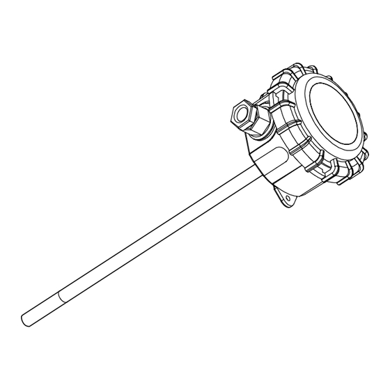
Dimensions
1
Pockets for use as immersion sensor; Brass (WB150) Stainless Steel (WS150)
Ø8 mm
(0.31")
Mounting flange for use as duct sensor
aCC/DF
3 x 4 mm diam. holes
on a 30 mm (1.18") pitch diameter
T/PI PRT Insertion Temperature Sensor Installation Instructions TG200825 Issue 3, 03-Aug-2015.
PRT Insertion Temperature Sensor
https://partners.trendcontrols.com
T/PI Installation Instructions (TG200825)
T/PI-L 400 mm (15.75")
T/PI-S 150 mm (5.91")
135 mm (5.31")
14 mm (0.53")
143 mm (5.63")
Universal Fitting Kit for immersion sensor use in existing
pockets
6 mm
hexagonal socket
compression
grub screw
fitting
Installation Instructions
57 mm (2.24")
Ø6.5 mm (0.25")
24 mm
(0.95")
R½" (BSPT)
brass bush
spring
T/PI
clip
1
Advertisement
Table of Contents

Related Manuals for TREND T/PI


Summary of Contents for TREND T/PI
-
Page 1: Installation Instructions
Mounting flange for use as duct sensor pockets aCC/DF clip 6 mm hexagonal socket compression grub screw fitting 3 x 4 mm diam. holes brass bush spring on a 30 mm (1.18”) pitch diameter T/PI PRT Insertion Temperature Sensor Installation Instructions TG200825 Issue 3, 03-Aug-2015. - Page 2 -40 °C +50 °C (e.g. downstream of mixing (-40 °F) (+122 °F) dampers, heating coils, cooling coils) otherwise -40 °C +110 °C use averaging sensor. (-40 °F) (+230 °F) T/PI PRT Insertion Temperature Sensor Installation Instructions TG200825 Issue 3, 03-Aug-2015.
- Page 3 *If used for chilled water ensure pocket is sealed around probe or fi ll pocket with thermally conducting oil to avoid the build up of condensation in bottom of pocket. T/PI PRT Insertion Temperature Sensor Installation Instructions TG200825 Issue 3, 03-Aug-2015.
- Page 4 3 off pilot holes 3 off No 6 ” s/s 30 mm (1.18”) self tapping screws <6 mm Adjust depth of probe Either: T/PI PRT Insertion Temperature Sensor Installation Instructions TG200825 Issue 3, 03-Aug-2015.
- Page 5 Note: if connecting to an IQ22x controller (including /ADL or / OC), do not connect directly to C (+24V), instead connect to AUX+ (+24V). Terminate screen at IQ end only polarity independent Analogue input channel confi gured for current T/PI PRT Insertion Temperature Sensor Installation Instructions TG200825 Issue 3, 03-Aug-2015.
- Page 6 Confi gure Controller IQ Confi guration Manual (90-1533) IQ3 Confi guration Manual (TE200768) IQ4 Confi guration Manual (TE201263) IQeco Confi guration Manual (TE201089) T/PI PRT Insertion Temperature Sensor Installation Instructions TG200825 Issue 3, 03-Aug-2015.
- Page 7 Note: for IQ3/4, the scaling mode and exponent do not need to be set up. For all other IQ controllers see Sensor Scaling Reference Card (TB100521A). Test System ∆ T T/PI PRT Insertion Temperature Sensor Installation Instructions TG200825 Issue 3, 03-Aug-2015.
- Page 8 Division of Honeywell Technologies Sàrl, Z.A. La Pièce, 16, 1180 Rolle, Switzerland by its Authorized Representative, Trend Control Systems Limited. Trend Control Systems Limited reserves the right to revise this publication from time to time and make changes to the content hereof without obligation to notify any person of such revisions or changes.
Need help?
Do you have a question about the T/PI and is the answer not in the manual?
Questions and answers