Table of Contents
Advertisement
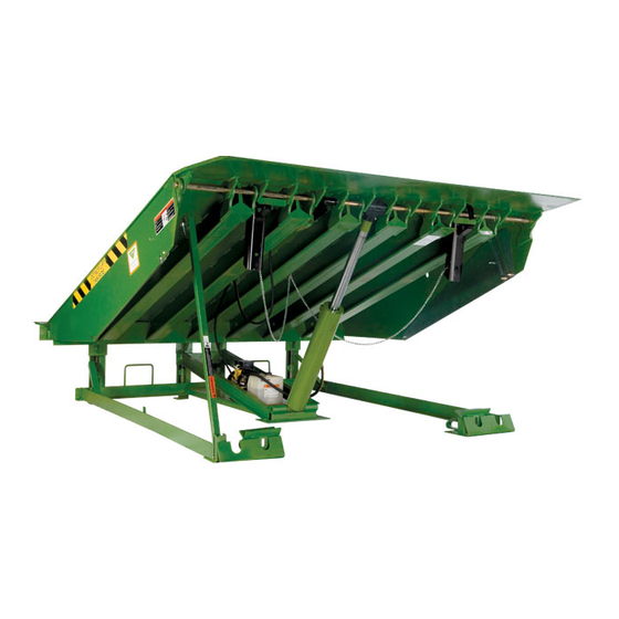
Hydraulic Dock Leveler
Model HK and HK-S
with One Button Control
This User's Manual applies to
dock levelers manufactured
beginning March 2014 with the
serial number 61106268 and
higher.
User's Manual
Do not install, operate or service this product unless you
Installation, Operations,
have read and understand the Safety Practices, Warnings,
and Installation and Operating Instructions contained in
Maintenance and Parts
this User's Manual. Failure to do so could result in death
or serious injury.
Part No. 6004753N
Advertisement
Table of Contents

Related Manuals for Kelley HK-S


Summary of Contents for Kelley HK-S
- Page 1 Hydraulic Dock Leveler Model HK and HK-S with One Button Control This User’s Manual applies to dock levelers manufactured beginning March 2014 with the serial number 61106268 and higher. User’s Manual Do not install, operate or service this product unless you...
-
Page 2: Table Of Contents
Distributor Information ..........72 Operations ..............25 Planned Maintenance ..........31 Maintenance And Lubrication ........32 inTroDUcTion Welcome and thank you for choosing this dock leveler from KELLEy . This dock leveler may be equipped with ® the optional ENERGy GUARD dock leveler sealing system. -
Page 3: Safety Practices
If you do not understand the instructions, ask your supervisor to explain them to you or call your local Kelley distributor. Ensure lip avoids contact with vehicle sides and cargo. If lip ®... -
Page 4: Owner's Responsibilities
owner’s resPonsibiLiTies The owner’s responsibilities include the following: The owner should recognize the inherent danger of the interface between dock and transport vehicle. The owner should, therefore, train and instruct operators in the safe use of dock leveling devices. When a transport vehicle is positioned as closely as practicable to a dock leveling device, there shall be at least 4"... -
Page 5: Ramp And Lip Grades
raMP anD LiP graDes Fig. 1 Ramp grade Lip grade Ramp and lip grades, Ramp and lip grades, Vehicle bed Vehicle bed % for each dock leveler length % for each dock leveler length position position 6' Leveler 8' Leveler 10' Leveler 6' Leveler 8' Leveler... -
Page 6: Installation
insTaLLaTion PiT cHeck subframe, remove it before placing the leveler into the 1. Check entire dock leveler pit for proper construction pit. Make sure the customer gets the user’s manual and according to certified pit drawings (publication 5567). Check is properly trained. to be sure that the pit walls are square and plumb. - Page 7 6' and 8' long levelers using a standard 19" subframe can be field converted to allow installation in a 24" pit by adding a 4" riser kit, Kelley Part No. 6004654. Install the new riser leveling feet. The riser blocks should be welded to the front frame supports prior to placing in the pit.
- Page 8 insTaLLaTion, continued noTe: noTe: Do not weld out the rear angle until after setting the front Check the pit floor for uneven or excess concrete in the area supports. around the leveling feet 1"-6" from the rear wall. Use chisel to level out area if necessary.
- Page 9 insTaLLaTion, continued LeVeLing THe fronT fraMe Fig. 8 6. Remove and discard the shipping tie down bolts located Transition angle at the lower end of the hinged lip assembly. See Fig. 14. Curb angle Before welding the dock leveler supports to the front Raises curb angle make sure that the dock leveler support legs rear...
- Page 10 insTaLLaTion, continued 11. If a field installed riser kit is being used, do not use Fig. 11 hydraulics to position leveler on maintenance strut before Door jamb cylinder support riser is in place. Use a suitable lifting Flush with floor at this point device to place leveler on maintenance strut per step 12 below, then position and weld in the cylinder support bracket.
- Page 11 insTaLLaTion, continued Fig. 14 Welding with the dock levelers power connected can damage electrical components. If the dock leveler has been previously connected, turn off power to control box Shipping tie and disconnect all electrical wires from junction box in down bolt rear pit wall before welding.
- Page 12 20. Mount dock bumpers to face of dock. Downhill welds are J bolts (3) per bumper unacceptable. See Fig. 17 or 18. furnished by Kelley Company, Inc. Locate 21. Wire in electrical cords and connect power to dock leveler. and weld to curb angle at time of bumper installation.
- Page 13 (See Operation section, page 25.) noTe: If you have any problems or questions using or operating the dock leveler, contact your supervisor or local Kelley ® distributor for assistance. 26. Optional (where applicable), install rear angle cap plugs (part number 6004488) into adjustment socket holes.
- Page 14 insTaLLaTion, continued insTaLLaTion TroUbLesHooTing The following procedures apply after the leveler is level in the pit. ProbLeM PossibLe caUse soLUTion 1) Leveler will not fit properly in pit. a) Pit is out of square with the sides. a) Align the sides parallel and equally spaced with the rear frame angle touching the rear curb angle in one place.
-
Page 15: Wiring Diagrams
wiring DiagraMs — conTroL box — sTanDarD noTe: Before doing any electrical work, make certain the power For 24V incoming power consult factory. is disconnected and properly tagged or locked off. All electrical work must be done by a qualified technician and meet all applicable codes. - Page 16 wiring DiagraMs — sTanDarD 6006450 — 208-240V, 3PH, 60 Hz 6006451 — 460-480V, 3PH, 60 Hz 6004753N — Hydraulic Dock Leveler - One Button Control — Safe Frame March 2014 ™ ©2014 4Front Engineered Solutions, Inc.
- Page 17 wiring DiagraMs — sTanDarD, continued 6006452 — 575V, 3PH, 60 Hz wiring DiagraMs wiTH inTerLock 6011372 — 120V, 1PH, 60 Hz March 2014 6004753N — Hydraulic Dock Leveler - One Button Control — Safe Frame ™ ©2014 4Front Engineered Solutions, Inc.
- Page 18 wiring DiagraMs wiTH inTerLock, continued 6011524 — 208/230V, 1PH, 60 Hz 6004753N — Hydraulic Dock Leveler - One Button Control — Safe Frame March 2014 ™ ©2014 4Front Engineered Solutions, Inc.
- Page 19 wiring DiagraMs wiTH inTerLock, continued 6011325 — 208V, 3PH, 60 Hz 6011761 — 240V, 3PH, 60 Hz March 2014 6004753N — Hydraulic Dock Leveler - One Button Control — Safe Frame ™ ©2014 4Front Engineered Solutions, Inc.
- Page 20 wiring DiagraMs wiTH inTerLock, continued 6011326 — 460-480V, 3PH, 60 Hz 6011651 — 575V, 3PH, 60 Hz 6004753N — Hydraulic Dock Leveler - One Button Control — Safe Frame March 2014 ™ ©2014 4Front Engineered Solutions, Inc.
- Page 21 wiring DiagraMs wiTH inTerLock anD aUTo-reTUrn To Dock 6011323 — 120V, 1PH, 60 Hz 6011324 — 208/240V, 1PH, 60 Hz March 2014 6004753N — Hydraulic Dock Leveler - One Button Control — Safe Frame ™ ©2014 4Front Engineered Solutions, Inc.
- Page 22 wiring DiagraMs wiTH inTerLock anD aUTo-reTUrn To Dock, continued 6011327 — 208V, 3PH, 60 Hz 6011762 — 240V, 3PH, 60 Hz 6004753N — Hydraulic Dock Leveler - One Button Control — Safe Frame March 2014 ™ ©2014 4Front Engineered Solutions, Inc.
- Page 23 wiring DiagraMs wiTH inTerLock anD aUTo-reTUrn To Dock, continued 6011328 — 460-480V, 3PH, 60 Hz March 2014 6004753N — Hydraulic Dock Leveler - One Button Control — Safe Frame ™ ©2014 4Front Engineered Solutions, Inc.
- Page 24 wiring DiagraMs wiTH inTerLock anD aUTo-reTUrn To Dock, continued 6011652 — 575V, 3PH, 60 Hz noTe: For 24V incoming power consult factory. 6004753N — Hydraulic Dock Leveler - One Button Control — Safe Frame March 2014 ™ ©2014 4Front Engineered Solutions, Inc.
-
Page 25: Operations
Vehicles pulling away from the dock unexpectedly can cause uncontrolled drop of the dock leveler which can result in death or serious injury. The maximum uncontrolled drop of a Kelley HK dock ® leveler from any position is 3 inches. - Page 26 sTanDarD oPeraTion Fig. 24 Do not operate the dock leveler when anyone is on or in front of it. Stay clear of the dock leveler when it is moving. Do not walk on dock leveler or lip until the lip is fully extended and supported by the vehicle bed.
- Page 27 sTanDarD oPeraTion, continued 7. To return the dock leveler to the stored position when loading or unloading is complete, or to load end loads: Before allowing vehicle to leave always return the dock 7.1 Push and hold the raise button. The ramp will leveler to its dock level (stored) position with the dock rise and the lip will lower.
- Page 28 Vehicles pulling away from the dock unexpectedly can cause uncontrolled drop of the dock leveler which can result in death or serious injury. The maximum uncontrolled drop of a Kelley HK dock ® leveler from any position is 3 inches.
- Page 29 oPeraTion, continued Dock LeVeLers wiTH aUTo-reTUrn To Dock Fig. 29 oPTion Do not operate the dock leveler when anyone is on or in front of it. Stay clear of the dock leveler when it is moving. Do not walk on dock leveler or lip until the lip is fully extended and supported by the vehicle bed.
- Page 30 oPeraTion, continued 7. To return the dock leveler to the stored position when loading or unloading is complete, or to load end loads: Before allowing vehicle to leave always return the dock 7.1 Turn the “ON/OFF” switch to the “ON” position. leveler to its dock level (stored) position with the dock level support legs supported by the front dock level 7.2 Push and hold the “RAISE”...
-
Page 31: Planned Maintenance
Every 90 days (quarterly) inspect all safety labels and tags to ensure they are on the dock leveler and are easily legible. If any are missing or require replacement, please call your local Kelley distributor. Fig. 34 6008554 (x2) (HK-S Model Only) 6008485 (x2) 138-837 (x2) 6015283 921-074 921-070... -
Page 32: Maintenance And Lubrication
MainTenance anD LUbricaTion Fig. 35 Lip hinge Dock level support leg Be certain, before climbing into the dock leveler pit or assembly cam and hinge doing any maintenance or repair under the dock leveler, that: 1) THE MAINTENANCE STRUT IS IN POSITION AND PINNED, LIP LOCK IS IN PLACE AND SUPPORTING THE LIP [see Fig. - Page 33 MainTenance anD LUbricaTion, continued Fig. 37 Legend Symbol Description Lubricate - oil Light oil - SAE 30 Lubricate - grease Molybdenum disulfide NLGI #2 Cleaning Lubricate pin (Location - frequency) on both ends of cylinder Visually inspect (Replace damaged or worn) Hydraulic reservoir See Note 1 Pit - 3 mo...
-
Page 34: Service Tools
serVice TooLs LiP Lock Before servicing the dock leveler, read and follow the Safety Practices on page 3, and the Operations Instruction The lip is free to move downward when it is released section on pages 16 through 18 of this User’s Manual. unless lip lock is in its support position. -
Page 35: Troubleshooting Guide
TroUbLesHooTing gUiDe, continued Fig. 39 Use type 5606 (low temp.) Be certain, before climbing into the dock leveler pit or hydraulic oil. doing any maintenance or repair under the dock leveler, that: 1) THE MAINTENANCE STRUT AND LIP LOCK ARE SECURELY IN PLACE, [see Fig. - Page 36 TroUbLesHooTing gUiDe, continued LiP exTenDs before raMP reacHes fULL aboVe Fig. 41 Dock PosiTion: Set lip sequence 1. Check lip sequence valve pressure setting. See Fig. 41. pressure at 1500 PSIG. Pressure gauge should LiP faiLs To DroP To THe PenDanT PosiTion wHen read 1500 PSI raMP is raiseD froM VeHicLe: before lip begins...
- Page 37 TroUbLesHooTing gUiDe, continued 2. Downward speed of the ramp is controlled by a needle Fig. 43 valve located in the pump/motor. Turn valve in to eliminate locking. See Fig. 43. See chart on page 39 for amount of time dock leveler should move from its fully raised position to full below dock position.
-
Page 38: Hydraulic Diagram
HyDraULic DiagraM Fig. 46 6004753N — Hydraulic Dock Leveler - One Button Control — Safe Frame March 2014 ™ ©2014 4Front Engineered Solutions, Inc. -
Page 39: Parts Replacement
ParTs rePLaceMenT conTroL box TransforMer — 3 PHase onLy Fig. 47 1. When replacing the transformer make sure jumper wires are installed per wiring diagrams, for appropriate phase and voltage. HyDraULic oiL Hoses 1. When removing hydraulic oil hose(s) remove from motor/pump assembly first then from cylinder assembly. -
Page 40: Parts List
Incorporation of replacement parts or modifications that weaken the structural integrity of the product, or in any way alter the product from its normal working condition at the time of purchase from Kelley could result in product malfunction, breakdown, premature wear, death Pit Depth or serious injury. - Page 41 ParTs LisT , continued MoDeL Hk raMP, LiP, anD Toe gUarD asseMbLies Fig. 50 March 2014 6004753N — Hydraulic Dock Leveler - One Button Control — Safe Frame ™ ©2014 4Front Engineered Solutions, Inc.
- Page 42 ParTs LisT, continued MoDeL Hk-s raMP, LiP, anD Toe gUarD asseMbLies Fig. 51 6004753N — Hydraulic Dock Leveler - One Button Control — Safe Frame March 2014 ™ ©2014 4Front Engineered Solutions, Inc.
- Page 43 ParTs LisT, continued raMP, LiP, anD Toe gUarD asseMbLies item Quantity Description Model Hk Model Hk-s LIP, 6FT WIDE, 30K AND 35K CAPACITy 16" X 6' W. 4 DEGREE BEND 711-858 — 16" X 6' W. 7 DEGREE BEND 711-857 —...
- Page 44 PIN, GROOVED 5/8" DIA. X 3-1/2 035-338 KLIPRING, EXT. 5/8" 049-060 LEVER, LIP LOCK 6015269 GUARD, SAFETy LIP - MODEL HK-S ONLy 6' W DOCK LEVELER 714-220 6-1/2' W DOCK LEVELER 714-219 7' W DOCK LEVELER 714-218 TOE GUARD, MIDDLE SLIDING - 19" PIT 6' LG.
- Page 45 ParTs LisT, continued sUbfraMe anD MainTenance sTrUT asseMbLies Fig. 52 item Quantity Description Part number MAINTENANCE POST, 6' LG. DECK WITH 20" BACKFRAME 713-308 MAINTENANCE POST, 6' LG. DECK WITH 24" BACKFRAME 6013622 MAINTENANCE POST, 8' LG. DECK WITH 20" BACKFRAME 708-882 MAINTENANCE POST, 8' LG.
- Page 46 2. Rear Angle Cap Plug item Quantity Description Part number RISER KIT (FIELD INSTALLED) 6004654 REAR ANGLE CAP PLUGS (KELLEy) OPTIONAL 6004487 6004753N — Hydraulic Dock Leveler - One Button Control — Safe Frame March 2014 ™ ©2014 4Front Engineered Solutions, Inc.
- Page 47 ParTs LisT , continued HyDraULic coMPonenTs anD reTUrn To Dock LeVeL swiTcH Fig. 54 March 2014 6004753N — Hydraulic Dock Leveler - One Button Control — Safe Frame ™ ©2014 4Front Engineered Solutions, Inc.
- Page 48 ParTs LisT, continued HyDraULic coMPonenTs anD reTUrn To Dock LeVeL swiTcH item Quantity Description Part number MOTOR/PUMP UNIT (INCLS. ITEMS 2 THRU 8) 100-120V, 1 PH, 50/60 Hz 6011436 200-240V, 1 PH, 50/60 Hz 6011437 190-240V, 3 PH, 50/60 Hz 6011438 380-480V, 3 PH, 50/60 Hz 6011439...
- Page 49 ParTs LisT, continued HyDraULic coMPonenTs anD reTUrn To Dock LeVeL swiTcH item Quantity Description Part number LIP LIFTER 712-377 CyLINDER, LIP 708-887 PIN, GROOVED, 3" LG 700-050 KLIPRING, EXT. 5/8" 049-060 PIN, GROOVED, 1-1/8" LG 700-049 HN-ANSI B18.2.2 - 1/4 - 20 214-161 AC INDUCT PROX SWITCH, N/O, 18 MM 625-040...
- Page 50 10' Lower seal. 6008172 Aluminum strip 6' upper 6008174 Aluminum strip 8' upper 6008176 Aluminum strip 10' upper 6008178 6' Kelley rear seal 6007671 6.5' Kelley rear seal 6007672 7' Kelley rear seal 6007673 TEK screws (not shown) 215702 Chain cup seal...
- Page 51 ParTs LisT, continued conTroL box asseMbLy — sTanDarD 6006461 — 120V, 1 PH, 50/60 Hz 6006462 — 208-240V, 1 PH, 60 Hz Fig. 56 item Quantity Description Part number — CONTROL BOX ASSEMBLy (INCLUDES ITEMS 1-6) 120V, 1 PH, 50/60 Hz 6006461 208-230V, 1 PH, 60 Hz 6006462...
- Page 52 ParTs LisT, continued conTroL box asseMbLy — sTanDarD 6006450 — 208-240V, 3PH, 60 Hz 6006451 — 460-480V, 3PH, 60 Hz 6006452 — 575V, 3PH, 60 Hz Fig. 57 6004753N — Hydraulic Dock Leveler - One Button Control — Safe Frame March 2014 ™...
- Page 53 ParTs LisT, continued conTroL box asseMbLy — sTanDarD 6006450 — 208-240V, 3PH, 60 Hz 6006451 — 460-480V, 3PH, 60 Hz 6006452 — 575V, 3PH, 60 Hz item Quantity Description Part number — CONTROL BOX ASSEMBLy (INCLUDES ITEMS 1-6) 208-230V, 3 PH, 50/60 Hz 6006450 460-480V, 3 PH, 50/60 Hz 6006451...
- Page 54 ParTs LisT, continued conTroL box asseMbLy wiTH oPTionaL inTerLock 6011372 — 120V, 1PH, 60 Hz Fig. 58 6004753N — Hydraulic Dock Leveler - One Button Control — Safe Frame March 2014 ™ ©2014 4Front Engineered Solutions, Inc.
- Page 55 OVERLOAD 12-18 AMPS 6013781 PUSH BUTTON, FLUSH, BLACK 6012561 CONTACT BLOCK SWITCH, NO, STD 6012563 BODy, MOUNTIN COLLAR 6012562 DECAL-KELLEy HP/HK-1PB 6014269 SCHEMATIC,HP/HK,1PB,1PH,120V 6011372S March 2014 6004753N — Hydraulic Dock Leveler - One Button Control — Safe Frame ™ ©2014 4Front Engineered Solutions, Inc.
- Page 56 ParTs LisT, continued conTroL box asseMbLy wiTH oPTionaL inTerLock 6011524 — 208/240V, 1PH, 60 Hz Fig. 59 6004753N — Hydraulic Dock Leveler - One Button Control — Safe Frame March 2014 ™ ©2014 4Front Engineered Solutions, Inc.
- Page 57 OVERLOAD 9-13 AMPS 6012560 PUSH BUTTON, FLUSH, BLACK 6012561 CONTACT BLOCK SWITCH, NO, STD 6012563 BODy, MOUNTIN COLLAR 6012562 DECAL-KELLEy HP/HK-1PB 6014269 SCHEMATIC,HP/HK,1PB,1PH,208-240V 6011524S March 2014 6004753N — Hydraulic Dock Leveler - One Button Control — Safe Frame ™ ©2014 4Front Engineered Solutions, Inc.
- Page 58 ParTs LisT, continued conTroL box asseMbLy wiTH oPTionaL inTerLock 6011325 — 208V, 3PH, 60 Hz 6011761 — 240V, 3PH, 60 Hz 6011326 — 460-480V, 3PH, 60 Hz Fig. 60 6004753N — Hydraulic Dock Leveler - One Button Control — Safe Frame March 2014 ™...
- Page 59 MICRON XFMR-208-600V/120-24V 6012567 PUSH BUTTON, FLUSH, BLACK 6012561 CONTACT BLOCK SWITCH, NO, STD 6012563 BODy, MOUNTIN COLLAR 6012562 DECAL-KELLEy HP/HK-1PB 6014269 FUSE, ATQR 1/2A, 600V, CC, FERRAz SHAWMUT 6011358 SCHEMATIC,HP/HK, 1PB, 3PH, 208V 6011325S SCHEMATIC, HP/HK, 1PB, 3PH, 240V 6011761S...
- Page 60 ParTs LisT, continued conTroL box asseMbLy wiTH oPTionaL inTerLock 6011651 — 575V, 3PH, 60 Hz Fig. 61 6004753N — Hydraulic Dock Leveler - One Button Control — Safe Frame March 2014 ™ ©2014 4Front Engineered Solutions, Inc.
- Page 61 6012567 PUSH BUTTON, FLUSH, BLACK 6012561 CONTACT BLOCK SWITCH, NO, STD 6012563 BODy, MOUNTIN COLLAR 6012562 DECAL-KELLEy HP/HK-1PB 6014269 FUSE, ATQR 1/4A, 600V, CC, FERRAz SHAWMUT 6011974 SCHEMATIC, HP/HK, 1PB, 3PH, 575V 6011651S March 2014 6004753N — Hydraulic Dock Leveler - One Button Control — Safe Frame ™...
- Page 62 ParTs LisT, continued conTroL box asseMbLy wiTH oPTionaL inTerLock anD aUTo-reTUrn To Dock 6011323 — 120V, 1PH, 60 Hz Fig. 62 6004753N — Hydraulic Dock Leveler - One Button Control — Safe Frame March 2014 ™ ©2014 4Front Engineered Solutions, Inc.
- Page 63 PUSH BUTTON, FLUSH, BLACK 6012561 SELECTOR SWITCH, 2 POSITION 6012565 CONTACT BLOCK SWITCH, NO, STD 6012563 BODy, MOUNTIN COLLAR 6012562 DECAL-KELLEy HP/HK-2PB 6014268 SCHEMATIC,HP/HK,2PB,1PH,120V 6011323S March 2014 6004753N — Hydraulic Dock Leveler - One Button Control — Safe Frame ™...
- Page 64 ParTs LisT, continued conTroL box asseMbLy wiTH oPTionaL inTerLock anD aUTo-reTUrn To Dock 6011324 — 208/240V, 1PH, 60 Hz Fig. 63 6004753N — Hydraulic Dock Leveler - One Button Control — Safe Frame March 2014 ™ ©2014 4Front Engineered Solutions, Inc.
- Page 65 PUSH BUTTON, FLUSH, BLACK 6012561 SELECTOR SWITCH, 2 POSITION 6012565 CONTACT BLOCK SWITCH, NO, STD 6012563 BODy, MOUNTIN COLLAR 6012562 DECAL-KELLEy HP/HK-2PB 6014268 SCHEMATIC,HP/HK,2PB,1PH,208-240V 6011324S March 2014 6004753N — Hydraulic Dock Leveler - One Button Control — Safe Frame ™...
- Page 66 ParTs LisT, continued conTroL box asseMbLy wiTH oPTionaL inTerLock anD aUTo-reTUrn To Dock 6011327 — 208V, 3PH, 60 Hz 6011762 — 240V, 3PH, 60 Hz 6011328 — 460-480V, 3PH, 60 Hz Fig. 64 6004753N — Hydraulic Dock Leveler - One Button Control — Safe Frame March 2014 ™...
- Page 67 PUSH BUTTON, FLUSH, BLACK 6012561 CONTACT BLOCK SWITCH, NO, STD 6012563 BODy, MOUNTIN COLLAR 6012562 SELECTOR SWITCH, 2 POSITION 6012565 DECAL-KELLEy HP/HK-2PB 6014268 FUSE, ATQR 1/2A, 600V, CC, FERRAz SHAWMUT 6011358 SCHEMATIC,HP/HK, 2PB, 3PH, 208V 6011327S SCHEMATIC, HP/HK, 2PB, 3PH, 240V 6011762S...
- Page 68 ParTs LisT, continued conTroL box asseMbLy wiTH oPTionaL inTerLock anD aUTo-reTUrn To Dock 6011652 — 575V, 3PH, 60 Hz Fig. 65 6004753N — Hydraulic Dock Leveler - One Button Control — Safe Frame March 2014 ™ ©2014 4Front Engineered Solutions, Inc.
- Page 69 6012561 CONTACT BLOCK SWITCH, NO, STD 6012563 BODy, MOUNTIN COLLAR 6012562 SELECTOR SWITCH, 2 POSITION 6012565 DECAL-KELLEy HP/HK-2PB 6014268 FUSE, ATQR 1/4A, 600V, CC, FERRAz SHAWMUT 6011974 SCHEMATIC, HP/HK, 2PB, 3PH, 575V 6011652S noTe: For 24V incoming power consult factory.
-
Page 70: Warranty Information
Kelley warrants that this DOCK LEVELER will be free from flaws in material and workmanship under normal use for a period of one (1) year from the earlier of 1) 60 days after the date of initial shipment by Kelley, or 2) the date of installation of the DOCK LEVELER by the original purchaser, provided that the owner maintains and operates the DOCK LEVELER in accordance with this User’s Manual. - Page 71 Kelley warrants that this DOCK LEVELER will be free from flaws in material and workmanship under normal use for a period of one (1) year from the earlier of 1) 60 days after the date of initial shipment by Kelley, or 2) the date of installation of the DOCK LEVELER by the original purchaser, provided that the owner maintains and operates the DOCK LEVELER in accordance with this User’s Manual.
-
Page 72: Distributor Information
Please direct questions about your dock leveler to your local distributor or to 4Front Engineered Solutions, Inc. Corporate Head Office: your local Kelley distributor is: ® 1612 Hutton Dr. Suite 140 Carrollton, TX. 75006 Tel. (972) 466-0707 Fax (972) 323-2661 HyDRAULICPLUS™...
Need help?
Do you have a question about the HK-S and is the answer not in the manual?
Questions and answers